EP0133567B1 - Sendeaufrufverfahren und Nachrichtensystem zum Feststellen von Dienstanforderungen - Google Patents
Sendeaufrufverfahren und Nachrichtensystem zum Feststellen von Dienstanforderungen Download PDFInfo
- Publication number
- EP0133567B1 EP0133567B1 EP84109357A EP84109357A EP0133567B1 EP 0133567 B1 EP0133567 B1 EP 0133567B1 EP 84109357 A EP84109357 A EP 84109357A EP 84109357 A EP84109357 A EP 84109357A EP 0133567 B1 EP0133567 B1 EP 0133567B1
- Authority
- EP
- European Patent Office
- Prior art keywords
- station
- masterstation
- operating
- polling
- stations
- Prior art date
- Legal status (The legal status is an assumption and is not a legal conclusion. Google has not performed a legal analysis and makes no representation as to the accuracy of the status listed.)
- Expired
Links
Images

Classifications
-
- G—PHYSICS
- G06—COMPUTING OR CALCULATING; COUNTING
- G06F—ELECTRIC DIGITAL DATA PROCESSING
- G06F13/00—Interconnection of, or transfer of information or other signals between, memories, input/output devices or central processing units
- G06F13/14—Handling requests for interconnection or transfer
- G06F13/36—Handling requests for interconnection or transfer for access to common bus or bus system
- G06F13/368—Handling requests for interconnection or transfer for access to common bus or bus system with decentralised access control
- G06F13/372—Handling requests for interconnection or transfer for access to common bus or bus system with decentralised access control using a time-dependent priority, e.g. individually loaded time counters or time slot
-
- H—ELECTRICITY
- H04—ELECTRIC COMMUNICATION TECHNIQUE
- H04L—TRANSMISSION OF DIGITAL INFORMATION, e.g. TELEGRAPHIC COMMUNICATION
- H04L12/00—Data switching networks
- H04L12/28—Data switching networks characterised by path configuration, e.g. LAN [Local Area Networks] or WAN [Wide Area Networks]
- H04L12/40—Bus networks
- H04L12/403—Bus networks with centralised control, e.g. polling
Definitions
- This invention relates to managing communication systems, and in particular to method and apparatus enabling a master control station to ascertain which of a number of operating stations using a common communication channel need service from the channel.
- Operating methods are known for the control of a plurality of stations using a common communication channel in which a masterstation establishes priorities and controls all use of the channel.
- a protocol is usually adopted that the operating stations will transmit only when directed to do so by a message from the master station. Since the operating stations do not initiate any communications, they cannot directly call the masterstation's attention to a need for service that arises, and it is necessary for the master station to send inquiries from time to time to each of the operating stations. Each operating station replies when queried by indicating what if any service it needs.
- a communication system managed as described above uses considerable time in the message exchange between the masterstation and the operating stations to provide the masterstation with the information about which stations need what service.
- the masterstation uses considerable time in the message exchange between the masterstation and the operating stations to provide the masterstation with the information about which stations need what service.
- the masterstation uses considerable time in the message exchange between the masterstation and the operating stations to provide the masterstation with the information about which stations need what service.
- there are many operating stations sharing the channel but ordinarily only a few of which are in need of any service a large utilization of the facility is expended in obtaining very sparse information.
- Another attempt to improve communication of workstations in a network with the master control station is the assignment of a recurring time window during which the workstation may initiate a transmission on a serial bus of the master control station excluding all other workstations, c.f. European patent application publication 0 052 956.
- the problem the invention addresses resides in shortening the time and lowering the load of the common communication channel for providing the masterstation with the information about which operating station need what service, i.e. improving the operation of a communication system.
- the masterstation initially directs a single inquiry signal to the aggregate of the operating stations and receives a response from this aggregate indicating by its structure which of the several individual stations currently needs service from the communication facility. Messages are thereafter exchanged between the masterstation and those operating stations only which need service to inform the masterstation as to the details of the service needed. The many message exchanges between the masterstation and the individual stations needing no service is eliminated.
- the invention provides a method for operating a communication system and such system which has a masterstation and a plurality of operating stations S i (where i takes various values to specificy a particular operating station) which distinguish from those of the prior art in that each operating system has a unique address and is assigned a delay time which is independent of the position of the station along the line, that each operating station replies to the polling sync signal only when service is required, and that the masterstation receives the replies from all the operating stations needing service and matches the delay for each reply to the address of the corresponding station and so forms a service need map for the whole system before he masterstation initiates an address message exchange with the operating stations needing service.
- the invention features the following steps and the means therefore: assign to each operation station S i an assigned delay value d i specific to the station such that each operating station's returned delay value is distinct for each station S i , store at each operating station S i its assigned delay value d i , transmit from the masterstation on the forward communication channel a distinctive polling sync signal, emit on the return channel from each operating station S i which needs service a polling reply signal indicative of needing to use a communication channel, the reply signal being emitted the assigned delay interval d i specific to the station after receiving the polling sync signal, receive at the masterstation the signals indicative of needing service, and associate the arrival times of such received signals with operating station addresses to ascertain which operating stations need service, and initiate from the masterstation an addressed message exchange with each operating station ascertained to need service to ascertain what service is needed.
- communication system 10 includes masterstation 18, a plurality of operating stations of which 20 is exemplary, and inbound coaxial cable 14 conveying signals from the masterstation and all operating stations to head 16, and outbound coaxial cable 12 conveying signals from head 16 to the masterstation and every operating station.
- a forward communication channel for tranmission of system supervisory signals from the masterstation to the operating stations is provided by a defined frequency band with transmissions from the masterstation propagating on the inbound cable to the head and thence on the outbound cable to every operating station.
- a return communication channel for transmission of system supervisory signals from every operating station to the masterstation is provided by a defined frequency band with transmissions from the operating stations propagating on the inbound cable to the head and thence on the outbound cable to the masterstation.
- Amplifiers, splitters, and other devices may be used as appropriate to control signal level and impedance of the channels as required by circumstances according to well known principles; such design details are unrelated to the subject invention.
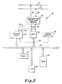
- masterstation 18 includes processor 30, memory 32, timing generating circuits 38, uart 36 (meaning universal assynchronous receiver-transmitter), polling logic 34, and transmitting-receiving modem 40.
- Bus 42 interconnects the processor, memory, uart and polling logic for tranfer of parallel data.
- Modulated carrier signal is transferred from cable 12 to modem 40 on link 58 and from modem 40 to cable 14 on link 60.
- Serial bit data is transferred as shown on links 46, 48, 50, and 52.
- Timing signals are transferred from timing generating circuits 38 to polling logic 34 on link 54. Other timing and control connections not shown are used to enable the processor to control the operations of the stations in accordance with well known design principles.
- Station 18 may communicate with other computers or peripherals through I/O devices 44.
- Operating station shown more particularly in Figure 3, includes processor 60, memory 62, uart 66 polling logic 68, delay switch bank 90, timing circuits 70, and transmitting-receiving modem 64.
- Connector 86 carrying carrier modulated signals connects cable 12 to modem 64; connector 86 connects modem 64 to cable 14.
- Connectors 76 and 78 interconnect polling logic 68 and modem 64; connectors 80 and 82 interconnect uart 66 and modem 64 (all carrying serial bit data).
- Connector 88 connects timing circuits 70 to polling logic 68.
- Bus 72 carrying parallel byte data interconnects processor 60, memory 62, uart 66, switchbank 90, and polling logic 68.
- the forward and return channels are used exclusively for communications between the masterstation and each of the operating stations to effect supervision and control of a communication network serving the several operating stations.
- Other communication channels are used to carry intercommunication among the operating stations. Messages are sent over the channels by modulated carrier in the form of packets, each with a start bit, 8 information bits, a parity bit (odd parity), and a stop bit.
- Each operating station has a unique address and is programmed to respond to messages starting with its own address and to those with a broadcast address. In order to avoid interferring transmissions on the commonly used communication channels, the operating stations are programmed to transmit only when directed to do so by the masterstation, which thus completely controls the use of the channels.
- the broadcast address is 0.
- each operating station S i (where i takes different values to designate particular stations) is assigned a delay value d i .
- the values of d i are chosen with reference to the propagation delays p i required to propagate a signal from the masterstation to the stations S i , and the propagation delays p i 'required to propagate a signal from the operating stations S i to the masterstation.
- the value of d i assigned is then stored by entering the value in delay switchbank 90.
- the propagation delays are negligible, and the assigned delay values are made equal to 128 ⁇ sec times the station address.
- the processor 30 of the masterstation initiates a poll by transmitting a distinctive five-byte message which is transmitted through the uart 36 and the modem 40 to channel 14.
- the first two bytes are the broadcast address, (i. e., 00000000, 00000000, in binary); the third byte is without information content, being reserved for system expansion; the fourth byte is 00000000 , a command code indicating the message is a polling request, and the fifth byte is used to generate the polling sync signal.
- This fifth byte is 1000 0000 in binary.
- the polling request message is processed by modem 40 and propagated over the communication channels to each of the operating stations.
- the operating stations may receive the polling request message at different times because of propagation delays.
- the message is received and demodulated by modem 64 and passed in serial bit form to uart 66, which puts the information bits on the bus 72 in parallel form.
- the processor 60 decodes the message and identifies it from the first four bytes of the message as a polling request. Then if the station needs service, the processor during the sequence of 0's in the fifth byte arms the polling logic 68.
- polling logic 68 When thus armed, polling logic 68 is triggered by the rising edge of the last bit of the fifth byte and begins to count timing pulses supplied on connector 88 from timing circuits 70. The rising count of these timing pulses is compared with the stored delay value d i in switchbank 90, and when the two are equal, the polling logic emits on connector 76 a 32 ⁇ sec reply pulse, indicating that the operating station needs service. This pulse is processed through modem 64 which transmits the pulse in modulated carrier form on connector 86 onto channel 14. If at the time the polling sync signal is received by a station, the station does not need service the polling logic is not armed and no transmission is made. An absence of transmission at the time d i thus constitutes a reply that no service is needed.
- the reply pulses from all the responding operating stations will be propagated along the return communication channel to the masterstation where, because of the manner of selecting the several d i with regard to the propagation delays, they will arrive without overlapping or interference.
- the transmissions are received and demodulated by modem 40 which sends to polling logic 34 over connector 50 a signal with a high voltage appearing at times D i corresponding to the return delays of the operating stations that transmitted a help-needed signal and with low voltage appearing at the times D i corresponding to the return delays of stations making no reply transmission.
- the polling logic 34 interprets these high or low voltages as logical 1's or 0's and enters them in successive positions of a serial in-parallel out, eight bit register, using the timing pulses received from timing circuits 38 to trigger the gating into successive bit positions.
- the parallelizing register is filled, corresponding to the receipt of the replies of eight operating stations, the register contents is transferred as bytes in parallel form onto bus 42 and lodged in a designated address in memory 32, and the polling logic proceeds to process the following reply pulses in the same manner until it has processed the replies from all the operating stations, with successive bytes transferred from the logic places in successive addresses in memory.
- a service need map in the designated portion of the masterstation memory 32 which has a bit corresponding to each operating station with the value of the bit indicating whether the corresponding station needs service.
- the memory map will be preponderantly 0's (indicating no need for service) with a sprinkling of 1's.
- the masterstation processor scans the map systematically and where it finds a 1 at a particular position it associates the position with an operating station address. This association may be done through a look up table or simply through an algorithm generating the station address from the map position.
- the masterstation processor 30 then, using the address, sends one or more addressed messages to the corresponding operating station to ascertain what service is required and provide that service.
- the processor initiates another polling cycle to obtain an updated map of service needs of the operating stations.
Landscapes
- Engineering & Computer Science (AREA)
- Theoretical Computer Science (AREA)
- Computer Networks & Wireless Communication (AREA)
- Signal Processing (AREA)
- Physics & Mathematics (AREA)
- General Engineering & Computer Science (AREA)
- General Physics & Mathematics (AREA)
- Small-Scale Networks (AREA)
Claims (2)
- Verfahren zum Betreiben eines Nachrichtensystems, das eine Hauptstation (18) und eine Vielzahl von Arbeitsstationen Si (20) (wobei i zur Spezifizierung einer bestimmten Arbeitsstation verschiedene Werte annimmt) aufweist, von denen jede Arbeitsstation eine eindeutige Adresse Ai hat, einen Vorwärts-Übertragungskanal, auf dem Signale von der Hauptstation zu allen aus der Vielzahl von Arbeitsstationen übertragen werden, einen Rückübertragungskanal, auf dem Signale von jeder Arbeitsstation zur Hauptstation übertragen werden, wobei die Laufzeit eines Signals auf dem Vorwärtskanal von der Hauptstation zu jeder Arbeitsstation Si Pi und die Laufzeit auf dem Rückkanal von jeder Arbeitsstation Si zur Hauptstation pi' beträgt,
gekennzeichnet durch:
Zuweisen an jede Arbeitsstation Si und Speichern eines für die Station spezifischen zugewiesenen Verzögerungswertes di, derart, daß bei jeder Arbeitsstation ihr Rücklauf-Verzögerungswert
der zugewiesene Verzögerungswert unabhängig von der Position der Station Si in der Leitung ist,
Übertragen eines charakteristischen Abfrage-Synchronisierungssignals von der Hauptstation aus,
Übertragen eines Abfrage-Antwortsignals von jeder Station Si aus nur bei Dienstanforderung, wobei das Antwortsignal am Ende des zugewiesenen Verzögerungsintervalls di nach Empfang des Abruf-Synchronisierungsignals ausgesandt wird,
Empfangen an der Hauptstation des Abfrage-Antwortsignals von allen Dienste anfordernden Stationen Si, und Zuordnen der Ankunftszeit zur Adresse Ai dieser Station, und
Auslösen von der Hauptstation aus eines Austauschs von adressierten Nachrichten mit jeder Dienste benötigenden Arbeitsstation. - Nachrichtensystem mit einer Hauptstation (18) und einer Vielzahl von Arbeitsstationen Si (20) (wobei zur Spezifizierung einer bestimmten Arbeitsstation i verschiedene Werte annimmt), von denen jede Arbeitsstation eine eindeutige Adresse Ai hat, einem Vorwärts-Übertragungskanal, auf dem Signale von der Hauptstation zu jeder aus der Vielzahl der Arbeitsstationen übertragen werden, einem Rück-Übertragungskanal, auf dem Signale von jeder der Arbeitsstationen zur Hauptstation übertragen werden, wobei die Laufzeit eines Signals auf dem Vorwärtskanal von der Hauptstation zu jeder Arbeitsstation Si pi und die Laufzeit auf dem Rückkanal von jeder Arbeitsstation zur Hauptstation pi' beträgt,
gekennzeichnet durch- eine Einrichtung (90) zum Speichern eines für jede Station Si spezifischen zugewiesenen Verzögerungswertes di an jeder Arbeitsstation (20),
wobei der zugewiesene Verzögerungswert von der Position der Station Si in der Leitung unabhängig ist,- eine Einrichtung (68) zum Übertragen eines Abfrage-Antwortsignals von jeder Station Si (20) nur bei Dienstanforderung, wobei das Antwortsignal am Ende des zugewiesenen Verzögerungsintervalls di nach Empfang des Abfrage-Synchronisierungssignals ausgesandt wird,- Einrichtungen (40, 34) an der Hauptstation (18) zum Empfangen des Abfrage-Antwortsignals von allen Dienste anfordernden Stationen (20) und Zuordnen der Ankunftszeit zur Adresse Ai der Station, und- eine Einrichtung (30) zum Auslösen von der Hauptstation (18) aus eines Austauschs von adressierten Nachrichten mit jeder Dienste benötigenden Arbeitsstation (20).
Applications Claiming Priority (2)
| Application Number | Priority Date | Filing Date | Title |
|---|---|---|---|
| US06/522,202 US4595921A (en) | 1983-08-11 | 1983-08-11 | Method of polling to ascertain service needs |
| US522202 | 1983-08-11 |
Publications (3)
| Publication Number | Publication Date |
|---|---|
| EP0133567A2 EP0133567A2 (de) | 1985-02-27 |
| EP0133567A3 EP0133567A3 (en) | 1987-12-02 |
| EP0133567B1 true EP0133567B1 (de) | 1992-05-06 |
Family
ID=24079885
Family Applications (1)
| Application Number | Title | Priority Date | Filing Date |
|---|---|---|---|
| EP84109357A Expired EP0133567B1 (de) | 1983-08-11 | 1984-08-07 | Sendeaufrufverfahren und Nachrichtensystem zum Feststellen von Dienstanforderungen |
Country Status (6)
| Country | Link |
|---|---|
| US (1) | US4595921A (de) |
| EP (1) | EP0133567B1 (de) |
| JP (1) | JPS6048638A (de) |
| AU (1) | AU571532B2 (de) |
| CA (1) | CA1218437A (de) |
| DE (1) | DE3485695D1 (de) |
Families Citing this family (44)
| Publication number | Priority date | Publication date | Assignee | Title |
|---|---|---|---|---|
| EP0160187B1 (de) * | 1984-03-26 | 1987-12-23 | BBC Brown Boveri AG | Verfahren zur Verarbeitung analoger Ausgangssignale von Strom- und Spannungswandlern sowie Einrichtung zur Durchführung des Verfahrens |
| EP0183273B1 (de) * | 1984-11-30 | 1992-09-23 | Nec Corporation | Flexibel anwendbares serielles Interface-System für eine Verbindung zwischen einer und mehreren Einheiten |
| US4652874A (en) * | 1984-12-24 | 1987-03-24 | Motorola, Inc. | Serial communication interface for a local network controller |
| JPS61171256A (ja) * | 1985-01-25 | 1986-08-01 | Nec Corp | デ−タ伝送時における割込通話方式 |
| US4688212A (en) * | 1985-01-31 | 1987-08-18 | Harris Corporation | Centralized image responsive telephone time slot interchange system |
| US4796025A (en) * | 1985-06-04 | 1989-01-03 | Simplex Time Recorder Co. | Monitor/control communication net with intelligent peripherals |
| JPH0666765B2 (ja) * | 1985-08-02 | 1994-08-24 | 河村電器産業株式会社 | デ−タウエイシステムにおける音声伝送方法 |
| US4910655A (en) * | 1985-08-14 | 1990-03-20 | Apple Computer, Inc. | Apparatus for transferring signals and data under the control of a host computer |
| US4912627A (en) * | 1985-08-14 | 1990-03-27 | Apple Computer, Inc. | Method for storing a second number as a command address of a first peripheral device and a third number as a command address of a second peripheral device |
| US4875158A (en) * | 1985-08-14 | 1989-10-17 | Apple Computer, Inc. | Method for requesting service by a device which generates a service request signal successively until it is serviced |
| US4918598A (en) * | 1985-08-14 | 1990-04-17 | Apple Computer, Inc. | Method for selectively activating and deactivating devices having same first address and different extended addresses |
| DE3679124D1 (de) * | 1985-09-11 | 1991-06-13 | Siemens Ag | Schaltungsanordnung zum uebertragen von datensignalen zwischen, ueber ein ringleitungssystem miteinander verbundenen steuereinrichtungen. |
| WO1987002205A1 (en) * | 1985-09-25 | 1987-04-09 | Australian Telecommunications Commission | Optical distribution system |
| US4796022A (en) * | 1985-12-13 | 1989-01-03 | Northern Telecom Limited | Double transit bus system |
| US4689619A (en) * | 1985-12-26 | 1987-08-25 | General Instrument Corporation | Method and apparatus for polling subscriber terminals |
| US5128664A (en) * | 1986-03-05 | 1992-07-07 | Ampex Corporation | Search technique for identifying slave devices connected to a serial bus |
| JPH0744524B2 (ja) * | 1986-03-05 | 1995-05-15 | 株式会社日立製作所 | デ−タ伝送装置 |
| US5109484A (en) * | 1986-04-09 | 1992-04-28 | International Business Machines Corporation | Self configuring terminal which polls loop network and generates list of connected devices for use in selectively downloading control programs |
| US4818984A (en) * | 1986-11-26 | 1989-04-04 | American Telephone And Telegraph Company, At&T Bell Laboratories | Broadcasting messages in a distributed processing system |
| JPH01122234A (ja) * | 1987-11-05 | 1989-05-15 | Pioneer Electron Corp | オーディオシステムにおけるポーリング方式 |
| US4811379A (en) * | 1987-12-21 | 1989-03-07 | Motorola, Inc. | Speak back paging system |
| US5184179A (en) * | 1988-05-17 | 1993-02-02 | Monitel Products Corp. | Photocopy monitoring system and method for monitoring copiers |
| US5077582A (en) * | 1988-05-17 | 1991-12-31 | Monitel Products Corp. | Photocopy monitoring system |
| US4940974A (en) * | 1988-11-01 | 1990-07-10 | Norand Corporation | Multiterminal communication system and method |
| JPH0748739B2 (ja) * | 1988-12-09 | 1995-05-24 | 富士通株式会社 | 多重アクセス制御方法および該方法を実施する多重アクセス制御システム |
| CA2010866C (en) * | 1989-02-28 | 1995-02-07 | Shigeo Amemiya | Polling communication system |
| US5200743A (en) * | 1989-09-01 | 1993-04-06 | Bently Nevada | Multiple remote sensor system for real time analog sensing and differential cummunication |
| JPH0817394B2 (ja) * | 1989-09-14 | 1996-02-21 | 松下電工株式会社 | 時分割多重伝送システムの割込処理方式 |
| SE464946B (sv) * | 1989-11-10 | 1991-07-01 | Philips Norden Ab | Oeverfoeringssystem innefattande en fraagestation och ett antal svarsstationer |
| US5130983A (en) * | 1990-03-27 | 1992-07-14 | Heffner Iii Horace W | Method of polling to determine service needs and the like |
| US5029209A (en) * | 1990-06-13 | 1991-07-02 | The Boeing Company | Pseudorandom, iterative method and apparatus for automatically creating addresses |
| FR2666187B1 (fr) * | 1990-08-24 | 1994-05-06 | Philippe Michel | Dispositif pour le dialogue a distance entre une station et un ou plusieurs objets portatifs. |
| EP0513549A3 (en) * | 1991-04-18 | 1993-12-15 | Canon Kk | Equipment control apparatus |
| EP0509524B1 (de) * | 1991-04-18 | 1999-11-10 | Canon Kabushiki Kaisha | Kommunikationssteuereinheit |
| DE69233799D1 (de) * | 1991-04-18 | 2011-01-05 | Canon Kk | Gerätüberwachungseinheit |
| EP0509530B1 (de) * | 1991-04-18 | 2007-02-28 | Canon Kabushiki Kaisha | Kommunikationsgerät und Verfahren |
| DE69232915T2 (de) * | 1991-04-18 | 2003-09-04 | Canon K.K., Tokio/Tokyo | Überwachungs- und Steuereinheit für eine Maschine |
| US5319785A (en) * | 1991-06-28 | 1994-06-07 | Digital Equipment Corporation | Polling of I/O device status comparison performed in the polled I/O device |
| US5452419A (en) * | 1992-03-06 | 1995-09-19 | Pitney Bowes Inc. | Serial communication control system between nodes having predetermined intervals for synchronous communications and mediating asynchronous communications for unused time in the predetermined intervals |
| CA2091093C (en) * | 1992-03-06 | 1999-07-06 | Peter C. Di Giulio | Event driven communication network |
| US5390351A (en) * | 1992-03-06 | 1995-02-14 | Pitney Bowes Inc. | System for communicating with plural nodes in predetermined intervals depended on integers assigned and changed based upon configuration thereof |
| US5574860A (en) * | 1993-03-11 | 1996-11-12 | Digital Equipment Corporation | Method of neighbor discovery over a multiaccess nonbroadcast medium |
| JPH0738879A (ja) * | 1993-07-16 | 1995-02-07 | Brother Ind Ltd | データ伝送装置 |
| DE19528437A1 (de) * | 1995-08-02 | 1997-02-06 | Siemens Ag | Verfahren zum Betreiben eines Datenübertragungssystems |
Family Cites Families (7)
| Publication number | Priority date | Publication date | Assignee | Title |
|---|---|---|---|---|
| CA1086397A (en) * | 1976-09-14 | 1980-09-23 | Charles G. Diefenderfer | Polling an data communication system having a pulse position to binary address conversion circuit |
| US4251865A (en) * | 1978-12-08 | 1981-02-17 | Motorola, Inc. | Polling system for a duplex communications link |
| US4306304A (en) * | 1979-07-31 | 1981-12-15 | Bell Telephone Laboratories, Incorporated | Digital loop synchronization circuit |
| JPS5669950A (en) * | 1979-11-13 | 1981-06-11 | Shinko Electric Co Ltd | General polling system of data transmission system |
| JPS5672554A (en) * | 1979-11-16 | 1981-06-16 | Toshiba Corp | Data transmission system |
| US4395710A (en) * | 1980-11-26 | 1983-07-26 | Westinghouse Electric Corp. | Bus access circuit for high speed digital data communication |
| GB2144310A (en) * | 1983-08-01 | 1985-02-27 | Philips Electronic Associated | Multiple-access communications system |
-
1983
- 1983-08-11 US US06/522,202 patent/US4595921A/en not_active Expired - Lifetime
-
1984
- 1984-05-25 JP JP59106331A patent/JPS6048638A/ja active Pending
- 1984-06-05 AU AU29092/84A patent/AU571532B2/en not_active Ceased
- 1984-07-12 CA CA000458702A patent/CA1218437A/en not_active Expired
- 1984-08-07 EP EP84109357A patent/EP0133567B1/de not_active Expired
- 1984-08-07 DE DE8484109357T patent/DE3485695D1/de not_active Expired - Lifetime
Also Published As
| Publication number | Publication date |
|---|---|
| AU571532B2 (en) | 1988-04-21 |
| CA1218437A (en) | 1987-02-24 |
| EP0133567A3 (en) | 1987-12-02 |
| EP0133567A2 (de) | 1985-02-27 |
| AU2909284A (en) | 1985-02-14 |
| US4595921A (en) | 1986-06-17 |
| DE3485695D1 (de) | 1992-06-11 |
| JPS6048638A (ja) | 1985-03-16 |
Similar Documents
| Publication | Publication Date | Title |
|---|---|---|
| EP0133567B1 (de) | Sendeaufrufverfahren und Nachrichtensystem zum Feststellen von Dienstanforderungen | |
| US4337465A (en) | Line driver circuit for a local area contention network | |
| EP0074864B1 (de) | System und Verfahren für das Nachschlagen von Namen in einem lokalen Bereichsnetz-Datenübertragungssystem | |
| US4550402A (en) | Data communication system | |
| US4410889A (en) | System and method for synchronizing variable-length messages in a local area network data communication system | |
| US4535450A (en) | Digital signal repeating system | |
| EP0183273B1 (de) | Flexibel anwendbares serielles Interface-System für eine Verbindung zwischen einer und mehreren Einheiten | |
| EP0051794B1 (de) | Datenvermittlungssystem der distributiven Strukturenart mit einem Direkt-Zugriffskanal für den Nachrichtendialog zwischen mehreren Datenverarbeitungseinheiten | |
| WO1987005763A1 (en) | Bridging techniques for local area networks | |
| US4430700A (en) | System and method for communication between nodes of a closed loop local communication path | |
| EP0439646B1 (de) | System und Protokoll für ein optisches Sternnetz mit minimaler Verzögerung zwischen aufeinanderfolgenden Datenpaketen | |
| US4413258A (en) | Interconnection for local area contention networks | |
| GB2117939A (en) | Data communication network and method of communication | |
| EP0374683B1 (de) | Konkurrenzverfahren für Kommunikationsnetze | |
| US4584575A (en) | Method and device for the asynchronous series communication on the multipoint type of a plurality of logic transceivers | |
| US3689872A (en) | Data retrieval and quote board multiplex system | |
| US4710918A (en) | Composite data transmission system | |
| EP0240873B1 (de) | Ein/Ausgabe-Einheit | |
| US4815070A (en) | Node apparatus for communication network having multi-conjunction architecture | |
| EP0279627A2 (de) | Übertragungsvorrichtung | |
| EP0105337A1 (de) | Datenübertragungsnetz und übertragungsverfahren | |
| JPH0158901B2 (de) | ||
| KR100260027B1 (ko) | 망관리 시스템에서의 최단 경로 탐색을 위한 셀구조 | |
| JPS63115436A (ja) | デ−タ伝送制御方式 | |
| JPS6050094B2 (ja) | データバス方式 |
Legal Events
| Date | Code | Title | Description |
|---|---|---|---|
| PUAI | Public reference made under article 153(3) epc to a published international application that has entered the european phase |
Free format text: ORIGINAL CODE: 0009012 |
|
| AK | Designated contracting states |
Designated state(s): BE DE FR GB |
|
| PUAL | Search report despatched |
Free format text: ORIGINAL CODE: 0009013 |
|
| AK | Designated contracting states |
Kind code of ref document: A3 Designated state(s): BE DE FR GB |
|
| 17P | Request for examination filed |
Effective date: 19880506 |
|
| 17Q | First examination report despatched |
Effective date: 19891108 |
|
| GRAA | (expected) grant |
Free format text: ORIGINAL CODE: 0009210 |
|
| AK | Designated contracting states |
Kind code of ref document: B1 Designated state(s): BE DE FR GB |
|
| REF | Corresponds to: |
Ref document number: 3485695 Country of ref document: DE Date of ref document: 19920611 |
|
| ET | Fr: translation filed | ||
| PLBE | No opposition filed within time limit |
Free format text: ORIGINAL CODE: 0009261 |
|
| STAA | Information on the status of an ep patent application or granted ep patent |
Free format text: STATUS: NO OPPOSITION FILED WITHIN TIME LIMIT |
|
| 26N | No opposition filed | ||
| PGFP | Annual fee paid to national office [announced via postgrant information from national office to epo] |
Ref country code: BE Payment date: 19930812 Year of fee payment: 10 |
|
| PG25 | Lapsed in a contracting state [announced via postgrant information from national office to epo] |
Ref country code: BE Effective date: 19940831 |
|
| BERE | Be: lapsed |
Owner name: WANG LABORATORIES INC. Effective date: 19940831 |
|
| REG | Reference to a national code |
Ref country code: FR Ref legal event code: TP |
|
| PGFP | Annual fee paid to national office [announced via postgrant information from national office to epo] |
Ref country code: FR Payment date: 20000719 Year of fee payment: 17 |
|
| PGFP | Annual fee paid to national office [announced via postgrant information from national office to epo] |
Ref country code: GB Payment date: 20000720 Year of fee payment: 17 Ref country code: DE Payment date: 20000720 Year of fee payment: 17 |
|
| PG25 | Lapsed in a contracting state [announced via postgrant information from national office to epo] |
Ref country code: GB Free format text: LAPSE BECAUSE OF NON-PAYMENT OF DUE FEES Effective date: 20010807 |
|
| GBPC | Gb: european patent ceased through non-payment of renewal fee |
Effective date: 20010807 |
|
| PG25 | Lapsed in a contracting state [announced via postgrant information from national office to epo] |
Ref country code: FR Free format text: LAPSE BECAUSE OF NON-PAYMENT OF DUE FEES Effective date: 20020430 |
|
| PG25 | Lapsed in a contracting state [announced via postgrant information from national office to epo] |
Ref country code: DE Free format text: LAPSE BECAUSE OF NON-PAYMENT OF DUE FEES Effective date: 20020501 |
|
| REG | Reference to a national code |
Ref country code: FR Ref legal event code: ST |