EP0133627A2 - Vorrichtung zur dichten Befestigung eines Rohres in der Öffnung einer Rohrhalteplatte - Google Patents
Vorrichtung zur dichten Befestigung eines Rohres in der Öffnung einer Rohrhalteplatte Download PDFInfo
- Publication number
- EP0133627A2 EP0133627A2 EP83111811A EP83111811A EP0133627A2 EP 0133627 A2 EP0133627 A2 EP 0133627A2 EP 83111811 A EP83111811 A EP 83111811A EP 83111811 A EP83111811 A EP 83111811A EP 0133627 A2 EP0133627 A2 EP 0133627A2
- Authority
- EP
- European Patent Office
- Prior art keywords
- pipe
- bead
- opening
- sleeve
- tube
- Prior art date
- Legal status (The legal status is an assumption and is not a legal conclusion. Google has not performed a legal analysis and makes no representation as to the accuracy of the status listed.)
- Granted
Links
Images
Classifications
-
- B—PERFORMING OPERATIONS; TRANSPORTING
- B65—CONVEYING; PACKING; STORING; HANDLING THIN OR FILAMENTARY MATERIAL
- B65D—CONTAINERS FOR STORAGE OR TRANSPORT OF ARTICLES OR MATERIALS, e.g. BAGS, BARRELS, BOTTLES, BOXES, CANS, CARTONS, CRATES, DRUMS, JARS, TANKS, HOPPERS, FORWARDING CONTAINERS; ACCESSORIES, CLOSURES, OR FITTINGS THEREFOR; PACKAGING ELEMENTS; PACKAGES
- B65D45/00—Clamping or other pressure-applying devices for securing or retaining closure members
-
- F—MECHANICAL ENGINEERING; LIGHTING; HEATING; WEAPONS; BLASTING
- F16—ENGINEERING ELEMENTS AND UNITS; GENERAL MEASURES FOR PRODUCING AND MAINTAINING EFFECTIVE FUNCTIONING OF MACHINES OR INSTALLATIONS; THERMAL INSULATION IN GENERAL
- F16L—PIPES; JOINTS OR FITTINGS FOR PIPES; SUPPORTS FOR PIPES, CABLES OR PROTECTIVE TUBING; MEANS FOR THERMAL INSULATION IN GENERAL
- F16L41/00—Branching pipes; Joining pipes to walls
- F16L41/08—Joining pipes to walls or pipes, the joined pipe axis being perpendicular to the plane of a wall or to the axis of another pipe
- F16L41/088—Joining pipes to walls or pipes, the joined pipe axis being perpendicular to the plane of a wall or to the axis of another pipe fixed using an elastic grommet between the extremity of the tube and the wall
Definitions
- the invention relates to a device for the tight fastening of a tube in the opening of a tube holding plate, consisting of a sleeve inserted into the gap between the tube and the opening made of elastic material, which rests with a flange arranged on the front side of the tube holding plate, which in the rear part to one Width of Gap overlapping bead is thickened and thereby rests under an elastic prestress on opposite wall areas of the: opening and the tube.
- Such a device is known from DE-OS 30 02 140. It consists of plastic and thus of a material that has only a very low elasticity. The flexibility is accordingly low and requires compliance with high-precision dimensional tolerances both in the manufacture of the actual device and in the manufacture of the parts to be sealed. This results in high manufacturing costs. Like the high surface quality required, they endanger an economical application. Vibrations induced due to operation often lead to premature failure.
- the invention has for its object to develop the device of the type mentioned in such a way that comparable disadvantages no longer occur.
- a tight fit of the pipe mounted in the pipe holding plate should also be ensured if vibrations of a changing frequency are initiated.
- the proposed device consists of a conventional elastomeric sealing material, for example of nitrile butadiene rubber, ethylene-pripipylene terpolymer rubber, vinylidene fluoride-hexafluoropropylene rubber, acrylonitrile-chloroprene rubber or epichlorohydrin rubber.
- a conventional elastomeric sealing material for example of nitrile butadiene rubber, ethylene-pripipylene terpolymer rubber, vinylidene fluoride-hexafluoropropylene rubber, acrylonitrile-chloroprene rubber or epichlorohydrin rubber.
- the hardness is in the range between 30 and 80 Shore A. Materials of this type are available at low cost. They can be inexpensively converted into the desired shape by methods known per se.
- the device lies at least with the front flange on the tube holding plate and with the outside of the bead on the conical surface of the opening that widens in the rearward direction. As a result, it is almost immovable in the installed state and causes a good axial fixation of the received tube. This is at least touched by the inside of the bead and the inside of the ring membrane. The latter has only a very small radial thickness. The pressure of the sealed medium therefore contributes directly to the pressing of the ring membrane against the outside diameter of the tube, which in addition to the good axial fixation results in a good sealing result.
- the flexibility of the ring membrane should be of crucial importance in this regard.
- the proposed device ensures a constant and firm contact between the device and the pipe received when relative movements occur, for example as a result of the initiation of vibrations of a changing frequency.
- the proposed device is therefore particularly well suited for sealing and holding the heat exchanger tubes of an air cooler in a motor vehicle. At the same time, it attenuates the noise emission from the surface of the mostly large-area components.
- the radial clamping of the pipe is characterized by a particularly good elasticity and softness, which favors the peeling insulation of the pipe. This effect is largely determined by the Ver Avoidance of a static compression of the sleeve wall between mutually parallel wall components of the tube and the bore. The actual clamping in the radial direction of the tube thus takes place exclusively between the conical surface of the bore and the cylindrical tube in the proposed embodiment. Relative displacements, for example as a result of vibrations, can be absorbed and damped in a better manner.
- the conical surfaces of the bore opposite one another should form an angle of 10 to 18 °.
- the proposed device is inserted into the prepared opening of the pipe holding plate in a first step.
- the bead arranged in the rear part prevents it from falling out automatically, which is why the work process can be carried out separately from the actual assembly of the pipes, if necessary.
- the associated pipes are inserted into the proposed device following their insertion into the openings. This is done by simply pushing it in, and it can be implemented particularly easily if the inside of the bead is delimited by a conical surface which has a diameter that decreases in the rearward direction. In this case, the use of a lubricant can usually be dispensed with.
- the sleeve has a conical surface on the outside between the bead and the ring membrane, which connects the two parts to one another.
- the required central assignment of the device to the opening is largely automatic in this case.
- the length of the ring membrane is not entirely arbitrary. It should preferably be 2 to 5 times the thickness.
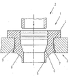
- the device 1 consists of a sleeve 4 arranged axially in the central area, which is cylindrically delimited essentially on the outside and on the inside and which is expanded on the outside to form a flange in the front part.
- the sleeve is thickened on the outside and inside to form a bead.
- the bulge is delimited on the inside by a conical surface 6, which has an inside diameter of 14.4 mm in the rear part and which ends at a cylinder surface, which at the same time delimits the ring membrane 5 on the inside.
- the bulge is delimited by a semicircular profile 7, which ends tangentially in the rear part in a plane extending perpendicular to the device axis and tangentially in the front part in a conical surface which encloses an angle of 10 ° with the device axis.
- the profile touches the conical surface of the opening of the tube holding plate, which is expanded in the rear part, axially in the rear third of its extension.
- a conical surface 8 is provided between the bead and the ring membrane 5. This is to facilitate the insertion of the device into the receiving opening. It encloses an angle of 45 ° with the device axis.
- the ring membrane 5 has a radial thickness of 0.3 mm with an axial length of 0.8 mm.
- the conical surface 6 forms an angle of 18 ° with the device axis. It ends in the rear area in the same axial plane with the rear boundary of the profile 7 and the tube holding plate 3.
Landscapes
- Engineering & Computer Science (AREA)
- Mechanical Engineering (AREA)
- General Engineering & Computer Science (AREA)
- Gasket Seals (AREA)
- Joints With Sleeves (AREA)
- Branch Pipes, Bends, And The Like (AREA)
- Joints With Pressure Members (AREA)
- Pressure Vessels And Lids Thereof (AREA)
- Snaps, Bayonet Connections, Set Pins, And Snap Rings (AREA)
- Heat-Exchange Devices With Radiators And Conduit Assemblies (AREA)
Abstract
Description
- Die Erfindung betrifft eine Vorrichtung zur dichten Befestigung eines Rohres in der Öffnung einer Rohrhalteplatte, bestehend aus einer in den Spalt zwischen Rohr und Öffnung eingefügten Hülse aus elastischem Material, die mit einem vorderseitig angeordneten Flansch an der Rohrhalteplatte anliegt, die im rückwärtigen Teil zu einem die Breite des Spaltes übersteigenden Wulst verdickt ist und die dadurch unter einer elastischen Vorspannung an einander gegenüberliegenden Wandungsbereichen der:Öffnung und des Rohres anliegt.
- Eine solche Vorrichtung ist aus der DE-OS 30 02 140 bekannt. Sie besteht aus Kunststoff und damit aus einem Werkstoff, der nur eine sehr geringe Elastizität aufweist. Die Nachgiebigkeit ist dementsprechend gering und erfordert die Einhaltung hochpräzisier Maßtoleranzen sowohl bei der Herstellung der eigentlichen Vorrichtung als auch bei der Herstellung der abzudichtenden Teile. Hohe Fertigungskosten sind hiervon die Folge. Sie gefährden ebenso wie die benötigte hohe Oberflächengüte eine wirtschaftliche Anwendung. Betriebsbedingt eingeleitete Schwingungen führen häufig zu vorzeitigem Ausfall.
- Der Erfindung liegt die Aufgabe zugrunde, die Vorrichtung der eingangs genannten Art derart weiter zu entwickeln, daß vergleichbare Nachteile nicht mehr auftreten. Zusätzlich soll ein fester Sitz des in der Rohrhalteplatte gelagerten Rohres auch dann gewährleistet sein, wenn Schwingungen einer wechselnden Frequenz eingeleitet werden.
- Diese Aufgabe wird erfindungsgemäß mit den kennzeichnenden Merkmalen des Patentanspruchs 1 gelöst. Auf vorteilhafte Ausgestaltungen nehmen die Unteransprüche Bezug.
- Die vorgeschlagene Vorrichtung besteht aus einem üblichen elastomeren Dichtungswerkstoff, beispielsweise aus Nitrilbutadien-Kautschuk, Äthylen-Prtipylen-Terpolymer-Kautschuk, Vinylidenfluorid-Hexafluorpropylen-Kautschuk, Acrylnitril-Chloropren-Kautschuk oder Epichlorhydrin-Kautschuk.
- Die Härte liegt etwa im Bereich zwischen 30 und 80 Shore A. Werkstoffe dieser Art sind kostengünstig verfügbar. Sie lassen sich durch an sich bekannte Verfahren kostengünstig in die gewünschte Gestalt überführen.
- Die Vorrichtung liegt zumindest mit dem vorderseitigen Flansch an der Rohrhalteplatte sowie mit der Außenseite des Wulstes an der sich in rückwärtiger Richtung erweiternden Kegelfläche der Öffnung an. Sie ist dadurch im eingebauten Zustand nahezu unverschiebbar und bewirkt eine gute axiale Festlegung des aufgenommenen Rohres. Dieses wird mindestens von der Innenseite des Wulstes sowie der Innenseite der Ringmembrane berührt. Letztere hat nur eine sehr geringe radiale Dicke. Der Druck des abgedichteten Mediums trägt daher unmittelbar zur Anpressung der Ringmembrane gegen den Außendurchmesser des Rohres bei, woraus neben der guten axialen Festlegung ein gutes Abdichtungsergebnis resultiert. Die Flexibilität der Ringmembrane dürfte diesbezüglich von entscheidender Bedeutung sein. Sie gewährleistet einen stetigen und festen Kontakt zwischen der Vorrichtung und dem aufgenommenen Rohr, wenn Relativbewegungen auftreten, beispielsweise als Folge der Einleitung von Schwingungen einer wechselnden Frequenz. Die vorgeschlagene Vorrichtung ist daher besonders gut geeignet für die Abdichtung und Halterung der Wärmetauscherrohre eines Luftkühlers in einem Kraftfahrzeug. Sie dämpft hier zugleich die Lärmemmision von der Oberfläche der zumeist großflächig ausgebildeten Einzelteile.
- Die radiale Einspannung des aufgenommenen Rohres zeichnet sich durch eine besonders gute Elastizität und Weichheit aus, was die schälltechnische Isolierung des Rohres begünstigt. Dieser Effekt wird maßgeblich durch die Vermeidung einer statischen Verpressunq der Hülsenwandung zwischen sich parallel zueinander erstreckenden Wandungsbestandteilen des Rohres und der Bohrung erzielt. Die eigentliche Einspannung in radialer Richtung des Rohres findet somit bei der vorgeschlagenen Ausführung ausschließlich zwischen der Kegelfläche der Bohrung und dem zylindrischen Rohr statt. Relativverlagerungen, beispielsweise als Folge von Schwingungen, können dadurch in besserer Weise weichelastisch aufgefangen und gedämpft'werden.
- Die einander gegenüberliegendenKegelflächen der Bohrung sollen einen Winkel von 10 bis 18° einschließen.
- Zur Montage eines entsprechenden Rohres wird die vorgeschlagene Vorrichtung in einem ersten Arbeitsschritt in die vorbereitete Öffnung der Rohrhalteplatte eingesetzt. Der im rückwärtigen Teil angeordnete Wulst verhindert ein selbsttätiges Herausfallen, weshalb der Arbeitsvorgang gegebenenfalls getrennt von der eigentlichen Montage der Rohre vorgenommen werden kann. Die Automation der Montage wird hierdurch sehr erleichtert. Sie läßt sich weiter vereinfachen, wenn mehrere Vorrichtungen in Form einer Matte zu einer Einheit zusammengefaßt sind. In diesem Falle erübrigt sich eine Einzelpositionierung und sämtliche Vorrichtungen können als geschlossene Einheit gleichzeitig in die zugehörigen Öffnungen der Rohrhalteplatte eingefügt werden. Dabei ergibt sich in Fällen, in denen die Matte zwischen den einzelnen Vorrichtungen in sich geschlossen und flüssigkeitsundurchlässig ist, ein zusätzlicher Korrosionsschutz der Rohrhalteplatte, was es erlaubt, bezüglich deren Herstellung auf kostengünstig verfügbare Materialien zurückzugreifen. In Fällen, in denen auf die Rohrhalteplatte zur Bildung der angrenzenden Kammer ein Oberteil aufgesetzt werden muß, kann eine entsprechende Matte im Bereich der Randzone zugleich als Dichtung für den Dichtrand des Oberteils ausgebildet sein. Beispielsweise die Herstellung des Lufkühlers für ein Kraftfahrzeug läßt sich hierdurch wesentlich verbilligen.
- Die zugehörigen Rohre werden in die vorgeschlagene Vorrichtung im Anschluß an deren Einfügung in die Öffnungen eingesetzt. Das geschieht durch einfaches Einschieben, und es läßt sich besonders einfach realisieren, wenn der Wulst innenseitig durch eine Kegelfläche begrenzt ist, die einen sich in rückwärtiger Richtung vermindernden Durchmesser aufweist. Auf die Verwendung eines Schmiermittels kann in diesem Falle zumeist verzichtet werden.
- Eine entsprechende Maßnahme ist selbstverständlich auch in bezug auf das Einfügen der Vorrichtung in die Öffnungen. denkbar. In diesem Falle weist die Hülse außenseitig zwischen dem Wulst und der Ringmembrane eine Kegelfläche auf, die beide Teile miteinander verbindet. Die erforderliche zentrische Zuordnung der Vorrichtung zu der Öffnung ergibt sich in diesem Falle weitgehend selbsttätig. Die Länge der Ringmembrane ist nicht völlig beliebig. Sie soll vorzugsweise 2- bis 5mal so groß sein wie die Dicke.
- Eine beispielhafte Ausführung der vorgeschlagenen Vorrichtung ist in der in der Anlage beigefügten Zeichnung dargestellt. Sie wird nachfolgend näher erläutert:
- Die Vorrichtung 1 besteht aus Gummi mit einer Härte Shore A von 75. Sie dient zur Abdichtung des Spaltes zwischen der Rohrhalteplatte 3 und einem nachträglich in die darin enthaltene Öffnung eingeführten Wärmetauscherrohr 2 eines Luftkühlers. Das Wärmetauscherrohr 2 hat einen Außendurchmesser von 15 mm. Es besteht aus Kupfer. Die Rohrhalteplatte 3 besteht aus Stahlblech. Sie hat eine Dicke von 3,5 mm.
- Die Vorrichtung 1 besteht aus einer axial im mittleren Bereich angeordneten Hülse 4, die im wesentlichen auf der Außen- und auf der Innenseite zylindrisch begrenzt ist und die im vorderen Teil außenseitig zu einem Flansch erweitert ist.
- Im rückwärtigen Teil, in der Zeichnung unten wiedergegeben, ist die Hülse außen- und innenseitig zu einem Wulst verdickt. Der Wulst wird auf der Innenseite durch eine Kegelfläche 6 begrenzt, die im rückwärtigen Teil einen Innendurchmesser von 14,4 mm aufweist und die an einer Zylinderfläche endet, die zugleich die Ringmembrane 5 auf der Innenseite begrenzt.
- Außenseitig ist der Wulst durch ein halbkreisförmiges Profil 7 begrenzt, das im rückwärtigen Teil tangential in eine sich senkrecht zur Vorrichtungsachse erstreckende Ebene ausläuft und im vorderseitigen Teil tangential in eine Kegelfläche, die mit der Vorrichtungsachse einen Winkel von 10° einschließt. Das Profil berührt die im rückwärtigen Teil erweiterte Kegelfläche der Öffnung der Rohrhalteplatte axial im hinteren Drittel ihrer Erstreckung. Zwischen dem Wulst und der Ringmembrane 5 ist eine Kegelfläche 8 vorgesehen. Diese soll das Einfügen der Vorrichtung in die aufnehmende Öffnung erleichtern. Sie schließt mit der Vorrichtungsachse einen Winkel von 45° ein. Die Ringmembrane 5 hat eine radiale Dicke von 0,3 mm bei einer axialen Länge von 0,8 mm. Die Kegelfläche 6 schließt mit der Vorrichtungsachse einen Winkel von 18° ein. Sie endet im rückwärtigen Bereich in gleicher axialer Ebene mit der rückwärtigen Begrenzung des Profils 7 und der Rohrhalteplatte 3.
Claims (5)
Applications Claiming Priority (2)
| Application Number | Priority Date | Filing Date | Title |
|---|---|---|---|
| DE19838322349U DE8322349U1 (de) | 1983-08-03 | 1983-08-03 | Vorrichtung zur dichten befestigung eines rohres in der oeffnung einer rohrhalteplatte |
| DE8322349U | 1983-08-03 |
Publications (4)
| Publication Number | Publication Date |
|---|---|
| EP0133627A2 true EP0133627A2 (de) | 1985-03-06 |
| EP0133627A3 EP0133627A3 (en) | 1985-07-10 |
| EP0133627B1 EP0133627B1 (de) | 1987-09-09 |
| EP0133627B2 EP0133627B2 (de) | 1991-12-18 |
Family
ID=6755809
Family Applications (1)
| Application Number | Title | Priority Date | Filing Date |
|---|---|---|---|
| EP83111811A Expired - Lifetime EP0133627B2 (de) | 1983-08-03 | 1983-11-25 | Vorrichtung zur dichten Befestigung eines Rohres in der Öffnung einer Rohrhalteplatte |
Country Status (5)
| Country | Link |
|---|---|
| EP (1) | EP0133627B2 (de) |
| JP (3) | JPS6078195A (de) |
| BR (1) | BR8400474A (de) |
| DE (2) | DE8322349U1 (de) |
| MX (1) | MX158840A (de) |
Cited By (4)
| Publication number | Priority date | Publication date | Assignee | Title |
|---|---|---|---|---|
| EP0332157A1 (de) * | 1988-03-08 | 1989-09-13 | Walter Roediger | Anordnung zur Verbindung einer Verteilvorrichtung mit einer Fluidzuleitung |
| EP0795712A1 (de) * | 1996-03-13 | 1997-09-17 | PT-Poly-Tec GmbH Vertrieb und Herstellung von Dichtungssystemen | Anschlussvorrichtung |
| WO2002103234A3 (de) * | 2001-06-15 | 2003-03-20 | Lauridsen Handel Imp As | Connection sleeve for use with pipes and wells |
| FR2999382A1 (fr) * | 2012-12-19 | 2014-06-20 | Evinox | Nourrisseur pour jeune betail avec dispositif de fixation ameliore pour tetine |
Families Citing this family (8)
| Publication number | Priority date | Publication date | Assignee | Title |
|---|---|---|---|---|
| DE3408835C2 (de) * | 1984-03-10 | 1987-01-29 | Fa. Carl Freudenberg, 6940 Weinheim | Warmwasserbereiter |
| JPS62292969A (ja) * | 1986-06-13 | 1987-12-19 | Kinugawa Rubber Ind Co Ltd | グロメツト |
| DE4106519A1 (de) * | 1991-03-01 | 1992-09-03 | Bayerische Motoren Werke Ag | Gummielastischer dichtring |
| DE29519780U1 (de) * | 1995-12-13 | 1996-02-15 | Kessel, Bernhard, 85101 Lenting | Manschette zum Abdichten einer Wanddurchbrechung |
| CN103291704B (zh) * | 2013-05-31 | 2015-09-09 | 湖南省金为型材有限公司 | 用于管材穿插连接的单边孔防水密封组件 |
| JP6240956B2 (ja) * | 2013-11-05 | 2017-12-06 | 株式会社デンソーウェーブ | ロボットのカバー取付構造、及びロボット |
| JP6670619B2 (ja) * | 2016-01-28 | 2020-03-25 | 株式会社カネカ | ソケット、プラグ及びこれらの接続構造 |
| CN107143654A (zh) * | 2017-06-28 | 2017-09-08 | 苏州克莱尔精密模具有限公司 | 一种弹性密封件 |
Family Cites Families (13)
| Publication number | Priority date | Publication date | Assignee | Title |
|---|---|---|---|---|
| DE7342159U (de) * | 1974-03-07 | Sueddeutsche Kuehlerfabrik Behr J | Dichtung für Wärmetauscher | |
| FR926488A (fr) * | 1946-04-12 | 1947-10-02 | Anciens Etablissements Panhard | Joint d'étanchéité notamment pour le raccord de tuyauteries sur des réservoirs |
| JPS516614Y1 (de) * | 1969-09-16 | 1976-02-23 | ||
| JPS5023863U (de) * | 1973-06-15 | 1975-03-18 | ||
| FR2239659B1 (de) * | 1973-08-01 | 1976-05-07 | Chausson Usines Sa | |
| AU498874B2 (en) * | 1974-09-02 | 1979-03-29 | Rieber + Son A/S | Moulding a pipe end socket |
| JPS5213125A (en) * | 1975-07-19 | 1977-02-01 | Kubota Ltd | Resin pipe joint reinforced with glass fiber and its process |
| JPS52121699U (de) * | 1976-03-12 | 1977-09-16 | ||
| JPS55151985U (de) * | 1979-04-16 | 1980-11-01 | ||
| NL7909293A (nl) * | 1979-12-21 | 1981-07-16 | Wavin Bv | Werkwijze voor het aanbrengen van een afdichtlichaam in een groef van een mof. |
| DE3002140C2 (de) * | 1980-01-22 | 1983-08-25 | Fa. Carl Freudenberg, 6940 Weinheim | Kunststoffdichtring |
| US4350351A (en) * | 1980-12-17 | 1982-09-21 | Martin A Eugene | Manhole joint gasket assembly and joint formed therewith |
| FR2517572B1 (fr) * | 1981-12-04 | 1985-06-14 | Valeo | Procede pour l'assemblage d'un tube avec une paroi a trou et dispositif pour la mise en oeuvre de ce procede |
-
1983
- 1983-08-03 DE DE19838322349U patent/DE8322349U1/de not_active Expired
- 1983-11-25 DE DE8383111811T patent/DE3373524D1/de not_active Expired
- 1983-11-25 EP EP83111811A patent/EP0133627B2/de not_active Expired - Lifetime
-
1984
- 1984-02-03 BR BR8400474A patent/BR8400474A/pt not_active IP Right Cessation
- 1984-05-11 MX MX201327A patent/MX158840A/es unknown
- 1984-07-25 JP JP59153316A patent/JPS6078195A/ja active Granted
- 1984-07-25 JP JP59153317A patent/JPS6078189A/ja active Granted
- 1984-07-30 JP JP59160202A patent/JPS6053278A/ja active Pending
Cited By (4)
| Publication number | Priority date | Publication date | Assignee | Title |
|---|---|---|---|---|
| EP0332157A1 (de) * | 1988-03-08 | 1989-09-13 | Walter Roediger | Anordnung zur Verbindung einer Verteilvorrichtung mit einer Fluidzuleitung |
| EP0795712A1 (de) * | 1996-03-13 | 1997-09-17 | PT-Poly-Tec GmbH Vertrieb und Herstellung von Dichtungssystemen | Anschlussvorrichtung |
| WO2002103234A3 (de) * | 2001-06-15 | 2003-03-20 | Lauridsen Handel Imp As | Connection sleeve for use with pipes and wells |
| FR2999382A1 (fr) * | 2012-12-19 | 2014-06-20 | Evinox | Nourrisseur pour jeune betail avec dispositif de fixation ameliore pour tetine |
Also Published As
| Publication number | Publication date |
|---|---|
| JPS6053278A (ja) | 1985-03-26 |
| JPH0369037B2 (de) | 1991-10-30 |
| DE8322349U1 (de) | 1983-11-17 |
| DE3373524D1 (en) | 1987-10-15 |
| MX158840A (es) | 1989-03-16 |
| JPS6078189A (ja) | 1985-05-02 |
| BR8400474A (pt) | 1985-03-26 |
| JPH0247636B2 (de) | 1990-10-22 |
| EP0133627B2 (de) | 1991-12-18 |
| EP0133627B1 (de) | 1987-09-09 |
| JPS6078195A (ja) | 1985-05-02 |
| EP0133627A3 (en) | 1985-07-10 |
Similar Documents
| Publication | Publication Date | Title |
|---|---|---|
| EP0897317B1 (de) | Endscheibe für ein ringfilterelement mit radial wirkender dichtung | |
| DE3717752C2 (de) | ||
| DE69411935T2 (de) | Schlauchschelle | |
| DE69526077T2 (de) | Rillenrohrkupplung und verbindungsverfahren | |
| EP1418370B1 (de) | Vorrichtung mit einer Dichtanordnung | |
| DE102004050302B4 (de) | Verbindung zweier Rohre und Dichtring für die Verbindung | |
| EP0133627B1 (de) | Vorrichtung zur dichten Befestigung eines Rohres in der Öffnung einer Rohrhalteplatte | |
| DE2905090A1 (de) | Gummilager mit hydraulischer daempfung | |
| DE2900026A1 (de) | Wellengelenk mit faltenbalgabdichtung | |
| DE69002721T2 (de) | Rohrverbindung. | |
| DE19932956A1 (de) | Schlauchverbindungsbaugruppe | |
| DE2714757A1 (de) | Rohrlochanordnung fuer eine durch aufweiten gebildete rohr-rohrplatten-verbindung | |
| DE2949838C2 (de) | Wellendichtring | |
| EP0111271B1 (de) | Leitungsrohr aus Kunststoff, insbesondere für Abwässer | |
| DE10036740A1 (de) | Schwingungsdämpfungseinrichtung, deren elastischer Körper eine gute Haltbarkeit aufweist | |
| DE8121384U1 (de) | Loesbare rohrkupplung und patrone zur bildung einer solchen rohrkupplung | |
| DE29702011U1 (de) | Baugruppe aus einem Gasgenerator und einem Abströmrohr für ein Fahrzeuginsassen-Rückhaltesystem | |
| DE3125830C1 (de) | In einem Kraftfahrzeug elastisch gelagerte Antriebs einheit | |
| DE602005005609T2 (de) | Verbindungshülse für Rohrabzweige | |
| DE69407283T2 (de) | Befestigungseinheit für ein rohr und ein verfahren zu deren herstellung | |
| EP0440890B1 (de) | Schlauchanschluss | |
| DE102007014003B4 (de) | Rohrverbindungsvorrichtung | |
| EP1384923B1 (de) | Dichtring zur Abdichtung eines Längenausgleichs einer Gelenkwelle | |
| DE3204193C1 (de) | Wellendichtung | |
| DE69309708T2 (de) | Verfahren zur herstellung eines ausflusselementes |
Legal Events
| Date | Code | Title | Description |
|---|---|---|---|
| PUAI | Public reference made under article 153(3) epc to a published international application that has entered the european phase |
Free format text: ORIGINAL CODE: 0009012 |
|
| AK | Designated contracting states |
Designated state(s): DE FR IT SE |
|
| PUAL | Search report despatched |
Free format text: ORIGINAL CODE: 0009013 |
|
| RHK1 | Main classification (correction) |
Ipc: F16L 5/02 |
|
| AK | Designated contracting states |
Designated state(s): DE FR IT SE |
|
| 17P | Request for examination filed |
Effective date: 19850514 |
|
| 17Q | First examination report despatched |
Effective date: 19860318 |
|
| ITF | It: translation for a ep patent filed | ||
| GRAA | (expected) grant |
Free format text: ORIGINAL CODE: 0009210 |
|
| AK | Designated contracting states |
Kind code of ref document: B1 Designated state(s): DE FR IT SE |
|
| ET | Fr: translation filed | ||
| REF | Corresponds to: |
Ref document number: 3373524 Country of ref document: DE Date of ref document: 19871015 |
|
| PLBI | Opposition filed |
Free format text: ORIGINAL CODE: 0009260 |
|
| 26 | Opposition filed |
Opponent name: SUEDDEUTSCHE KUEHLERFABRIK JULIUS FR. BEHR GMBH & Effective date: 19880609 |
|
| PLAB | Opposition data, opponent's data or that of the opponent's representative modified |
Free format text: ORIGINAL CODE: 0009299OPPO |
|
| ITTA | It: last paid annual fee | ||
| R26 | Opposition filed (corrected) |
Opponent name: BEHR GMBH & CO. Effective date: 19880609 |
|
| ITF | It: translation for a ep patent filed | ||
| PUAH | Patent maintained in amended form |
Free format text: ORIGINAL CODE: 0009272 |
|
| STAA | Information on the status of an ep patent application or granted ep patent |
Free format text: STATUS: PATENT MAINTAINED AS AMENDED |
|
| 27A | Patent maintained in amended form |
Effective date: 19911218 |
|
| AK | Designated contracting states |
Kind code of ref document: B2 Designated state(s): DE FR IT SE |
|
| ET3 | Fr: translation filed ** decision concerning opposition | ||
| EAL | Se: european patent in force in sweden |
Ref document number: 83111811.2 |
|
| PGFP | Annual fee paid to national office [announced via postgrant information from national office to epo] |
Ref country code: DE Payment date: 20021025 Year of fee payment: 20 |
|
| PGFP | Annual fee paid to national office [announced via postgrant information from national office to epo] |
Ref country code: FR Payment date: 20021119 Year of fee payment: 20 |
|
| PGFP | Annual fee paid to national office [announced via postgrant information from national office to epo] |
Ref country code: SE Payment date: 20021125 Year of fee payment: 20 |
|
| EUG | Se: european patent has lapsed |