EP0133706A2 - Verfahren und System zur Aufzeichnung und Rückgewinnung von in mehreren Kanälen abgetasteten Daten - Google Patents
Verfahren und System zur Aufzeichnung und Rückgewinnung von in mehreren Kanälen abgetasteten Daten Download PDFInfo
- Publication number
- EP0133706A2 EP0133706A2 EP84109554A EP84109554A EP0133706A2 EP 0133706 A2 EP0133706 A2 EP 0133706A2 EP 84109554 A EP84109554 A EP 84109554A EP 84109554 A EP84109554 A EP 84109554A EP 0133706 A2 EP0133706 A2 EP 0133706A2
- Authority
- EP
- European Patent Office
- Prior art keywords
- data
- blocks
- disk
- buffer memory
- block
- Prior art date
- Legal status (The legal status is an assumption and is not a legal conclusion. Google has not performed a legal analysis and makes no representation as to the accuracy of the status listed.)
- Withdrawn
Links
Images


Classifications
-
- G—PHYSICS
- G11—INFORMATION STORAGE
- G11B—INFORMATION STORAGE BASED ON RELATIVE MOVEMENT BETWEEN RECORD CARRIER AND TRANSDUCER
- G11B27/00—Editing; Indexing; Addressing; Timing or synchronising; Monitoring; Measuring tape travel
- G11B27/10—Indexing; Addressing; Timing or synchronising; Measuring tape travel
- G11B27/102—Programmed access in sequence to addressed parts of tracks of operating record carriers
- G11B27/105—Programmed access in sequence to addressed parts of tracks of operating record carriers of operating discs
-
- G—PHYSICS
- G11—INFORMATION STORAGE
- G11B—INFORMATION STORAGE BASED ON RELATIVE MOVEMENT BETWEEN RECORD CARRIER AND TRANSDUCER
- G11B20/00—Signal processing not specific to the method of recording or reproducing; Circuits therefor
- G11B20/10—Digital recording or reproducing
-
- G—PHYSICS
- G11—INFORMATION STORAGE
- G11B—INFORMATION STORAGE BASED ON RELATIVE MOVEMENT BETWEEN RECORD CARRIER AND TRANSDUCER
- G11B20/00—Signal processing not specific to the method of recording or reproducing; Circuits therefor
- G11B20/10—Digital recording or reproducing
- G11B20/12—Formatting, e.g. arrangement of data block or words on the record carriers
- G11B20/1217—Formatting, e.g. arrangement of data block or words on the record carriers on discs
- G11B20/1251—Formatting, e.g. arrangement of data block or words on the record carriers on discs for continuous data, e.g. digitised analog information signals, pulse code modulated [PCM] data
-
- G—PHYSICS
- G11—INFORMATION STORAGE
- G11B—INFORMATION STORAGE BASED ON RELATIVE MOVEMENT BETWEEN RECORD CARRIER AND TRANSDUCER
- G11B20/00—Signal processing not specific to the method of recording or reproducing; Circuits therefor
- G11B20/10—Digital recording or reproducing
- G11B20/18—Error detection or correction; Testing, e.g. of drop-outs
-
- G—PHYSICS
- G11—INFORMATION STORAGE
- G11B—INFORMATION STORAGE BASED ON RELATIVE MOVEMENT BETWEEN RECORD CARRIER AND TRANSDUCER
- G11B27/00—Editing; Indexing; Addressing; Timing or synchronising; Monitoring; Measuring tape travel
- G11B27/02—Editing, e.g. varying the order of information signals recorded on, or reproduced from, record carriers
- G11B27/031—Electronic editing of digitised analogue information signals, e.g. audio or video signals
- G11B27/034—Electronic editing of digitised analogue information signals, e.g. audio or video signals on discs
-
- G—PHYSICS
- G11—INFORMATION STORAGE
- G11B—INFORMATION STORAGE BASED ON RELATIVE MOVEMENT BETWEEN RECORD CARRIER AND TRANSDUCER
- G11B5/00—Recording by magnetisation or demagnetisation of a record carrier; Reproducing by magnetic means; Record carriers therefor
- G11B5/012—Recording on, or reproducing or erasing from, magnetic disks
-
- G—PHYSICS
- G11—INFORMATION STORAGE
- G11B—INFORMATION STORAGE BASED ON RELATIVE MOVEMENT BETWEEN RECORD CARRIER AND TRANSDUCER
- G11B20/00—Signal processing not specific to the method of recording or reproducing; Circuits therefor
- G11B20/10—Digital recording or reproducing
- G11B20/10527—Audio or video recording; Data buffering arrangements
- G11B2020/10537—Audio or video recording
- G11B2020/10546—Audio or video recording specifically adapted for audio data
-
- G—PHYSICS
- G11—INFORMATION STORAGE
- G11B—INFORMATION STORAGE BASED ON RELATIVE MOVEMENT BETWEEN RECORD CARRIER AND TRANSDUCER
- G11B20/00—Signal processing not specific to the method of recording or reproducing; Circuits therefor
- G11B20/10—Digital recording or reproducing
- G11B20/10527—Audio or video recording; Data buffering arrangements
- G11B2020/10537—Audio or video recording
- G11B2020/10592—Audio or video recording specifically adapted for recording or reproducing multichannel signals
-
- G—PHYSICS
- G11—INFORMATION STORAGE
- G11B—INFORMATION STORAGE BASED ON RELATIVE MOVEMENT BETWEEN RECORD CARRIER AND TRANSDUCER
- G11B2220/00—Record carriers by type
- G11B2220/20—Disc-shaped record carriers
-
- G—PHYSICS
- G11—INFORMATION STORAGE
- G11B—INFORMATION STORAGE BASED ON RELATIVE MOVEMENT BETWEEN RECORD CARRIER AND TRANSDUCER
- G11B2220/00—Record carriers by type
- G11B2220/20—Disc-shaped record carriers
- G11B2220/25—Disc-shaped record carriers characterised in that the disc is based on a specific recording technology
- G11B2220/2508—Magnetic discs
-
- G—PHYSICS
- G11—INFORMATION STORAGE
- G11B—INFORMATION STORAGE BASED ON RELATIVE MOVEMENT BETWEEN RECORD CARRIER AND TRANSDUCER
- G11B2220/00—Record carriers by type
- G11B2220/60—Solid state media
- G11B2220/65—Solid state media wherein solid state memory is used for storing indexing information or metadata
-
- G—PHYSICS
- G11—INFORMATION STORAGE
- G11B—INFORMATION STORAGE BASED ON RELATIVE MOVEMENT BETWEEN RECORD CARRIER AND TRANSDUCER
- G11B27/00—Editing; Indexing; Addressing; Timing or synchronising; Monitoring; Measuring tape travel
- G11B27/10—Indexing; Addressing; Timing or synchronising; Measuring tape travel
- G11B27/11—Indexing; Addressing; Timing or synchronising; Measuring tape travel by using information not detectable on the record carrier
Definitions
- This invention relates generally to multi-channel data transfer between, on one hand, a bulk storage media requiring unequal time to access blocks of data, such as a magnetic disk system read by one or more heads moved across the disk surface, and, on the other hand, a source/consumer of data or an intermediate buffer memory therefore.
- the predominent technique for recording multi-channel digital data on a magnetic disk is to interleave data of the various channels in sequence.
- the most common type of currently available disk recording system uses a single read/write head for each rotating magnetic recording surface, and most multi-disk, multi-head systems still only allow one head to be operable for reading or writing at a time.
- data from the several channels is effectively formed into a single serial stream which is then written onto the disk and later read therefrom to recover the serial stream and thus reconstruct the multiple channel data.
- Such a system is quite satisfactory for simple writing and reading of data but is quite awkward if editing is desired to be done on the recorded digital data. It is difficult to access the data of one channel independently of the others. It is practically impossible to time shift the data of one channel with respect to that of another. Such independence and time shifting is particularly desireable in editing multi-channel digital sound data in many applications such as in constructing a multi-channel movie sound track from various data files.
- a fixed disk memory 11 is connected through a buffer memory 13 by lines 15 to equipment which utilizes data recorded in the mass storage medium 11 through lines 19 and which also provides data for storage in the system 11 through lines 21.
- the source of data within the equipment 17 may be any multi-channel stream of data wherein it is desired to be able to access the data within the memory system 11 for each channel independent of the other.
- the utilization of data received in the lines 19 from the disk system 11 can be, for example, sound editing equipment within the utilization equipment 17, which receives the individual channel data from the disk system 11 through the lines 19.
- the number of independent channels are assumed to be three in number, thus the data path 19 includes three separate lines for receiving multi-channel information from the disk system 11 and the data path 21 includes three lines for storing digital information on the disk system 11.
- any other number, two or more, of channels may take advantage of the various aspects of the present invention.
- a computer 23 In order to control the operation of the disk system 11, the buffer memory 13 and the data source and destination equipment 17, a computer 23 communicates control signals over bus 25 to the disk system 11 and over bus 27 to the source and destination equipment 17. Controlling programs are stored in a computer memory 29 which are communicated with the computer 23 over a bus 31. The memory 29 also keeps track of the physical addresses within the disk storage system 11 of the various components of the channels of data recorded on it for later access and reconstruction of the individual data streams.
- FIG. 2 the essential components of a fixed disk storage system 11 are illustrated.
- a plurality of circular disks 33-35 are held concentric with each other and rotated about their common access 37 at a constant high rate of speed.
- Each disk has a magnetic recording surface on its top and bottom.
- Each disk such as the disk 33, includes a pair of arms 39 and 41 that are moved back and forth across the disk in a radial direction by electromechanical mechanisms 41 in response to control signals on a bus 43 from a disk controlling circuit 45.
- Each of the arms has a single read/write head at its end, such as at the end of the arm 39, from which or to which a serial stream of data is passed on a single conductor 47 that is connected to the disk controller 45.
- the data being read from the disk or being written onto the disk is communicated with the buffer memory 13 over the lines 15, while signals controlling the position of the read/write head arms 39 etc. comes to the controller 45 over the control bus 25.
- a primary characteristic of such a disk type of storage device with which the present invention is concerned is its periods of latency; that is, the periods of time in which the read/write head and disk surface are moving relative to each other from the position of one AU of data to that of another, periods of time when data is not being transferred.
- the time for accessing an AU of data varies, depending on how far apart the AU is from the position of the last AU accessed on the disk.
- the multi-channel data lines 19 and 2l are schematically illustrated in Figure 2 as real time streams of data that are broken into blocks or allocation units (AU's), such as AU 61 shown in one of the channels for data coming into the buffer memory 13.
- a real time line 63 shows the AU's for each of the three channels which are at a particular instant of time being written into the buffer memory 13 for temporary storage.
- the three streams of data illustrated for the lines 19 in Figure 2 that are being read out of the buffer memory 13 are shown relative to a real time line 65 that identifies a portion of the data stream at the time of the snapshot of Figure 2 that is being presented to data utilization equipment within the source-and destination equipment block l7 of Figure 1.
- the techniques of the present invention allow data to be written onto the disk simultaneously with reading data from the disk, although one or another of these functions can be performed alone.
- Each of the channels of data is considered to be an integral data file separate from the others and is so treated, thereby permitting each channel of data to be individually accessed and/or shifted in time with respect to the other channels.
- each track of data recorded on the disk is " divided into 32 sectors therearound. That is, 32 sectors of data may be recovered from the disk system 11 for a single revolution of the disk depending upon which read/write head is activated. Only one such head may be activated at one time in this common type of equipment.
- the block of data or allocation unit (AU) size is selected to occupy 62 or 63 sectors of data which represents about one-third to one-half second of sound at a 48 KHz. sampling rate.
- an AU is sized to be one or two sectors less than two tracks full of data, thus permitting switching between tracks on the same cylinder during the time for rotation of only the one or two sectors, thereby minimizing rotational latency during such switching.
- the individual AU's for any particular channel, or all of the channels together, are not recorded in physical sequence on the rotating disks but rather are scattered throughout the disk, a table in computer memory 29 keeping track of the physical disk addresses for the various AU's that need to be put back together when reading the disk to form the continuous stream of data for each channel. Because of seek latency and rotational latency of the disk storage system, scattered storage, as opposed to storing each AU on the disk physically adjacent the next AU in time sequence, tends to greatly increase the expected access time for a single file.
- the overall data transfer efficiency of the disk system may be viewed as having a maximum data transfer bandwidth that occurs in completely sequential recording where the read/write heads move in order from one cylinder to the other across the disk. But the theoretical maximum bandwidth is reduced when a stream of data is broken up into AU's that are recorded at scattered cylinders because of the latency discussed above.
- scattered storage is undesireable and not to be used in a situation where bandwidth is attempted to be maximized.
- scattered storage actually improves bandwidth overall when multiple files or channels of data are being recorded and retrieved from a disk system wherein the flexibility of being able to access a single file or channel is desired, as well as to shift the relative timing of one file or channel with respect to the others.
- Scattered storage is highly desireable to permit such separate access and timing shift. Scattered storage is not by itself new since many computer operating systems have utilized it. But the transfer efficiency or bandwidth of those systems is only five or ten percent of the theoretical maximum disk access bandwidth. The technique of the present invention, however, allows operation approaching 80% of the maximum bandwidth.
- alternate data tracks 51, 55 and 59 begin the recording of each AU at sector zero.
- the interleaved alternate tracks 53, 57 etc. begin'the AU's recorded therein at sector 16, 180 degrees displaced from the beginning zero sector of adjacent tracks.
- This has the significant advantage of being able to move the read/write heads to a new cylinder and begin reading data therefrom within one-half revolution of the track where the reading of data in another AU has been concluded.
- the heads of the specific equipment previously described can move up to eleven cylinders in either direction within one-half revolution..
- the normal technique as used by others is to begin recording of the AU's at the zero sector of each track, thus requiring a minimum of one revolution of wasted time where no reading can take place when the head must move from one track to another.
- the computer memory 29 keeps track of the beginning sector for each of the different recording tracks on the disks.
- the static technique of physical data orientation on the disk just described is simple and easy to utilize in software systems. However, an even greater efficiency is possible, but more complex software is therefore necessary to utilize, if more than two different starting sectors are chosen.
- the generality may be expressed by the following mathematical relationship which gives the starting sector for a given disk data track: (SIN)(cyl. modulo N), where S is the total number of sectors around one track, N being the number of different rotational starting sectors desired to be included, and where "cyl. modulo N" is a remainder resulting from dividing a particular track number whose starting sector is to be determined by the number N.
- the initial starting sector of one track is zero, the next is 16, the next is zero, and so on completely across the disk.
- N is chosen to be 4
- the starting sector of track zero is zero, that of track 1 is 8, that of track 2 is 16, that of track 3 is 24 and that of track of 4 is zero, thus repeating the pattern in that manner across the disk.
- the starting sectors vary in a periodic fashion across the disk.
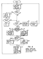
- Figure 5 shows in the form of a flow chart the method steps involved in deciding which AU to access and read from the disk at a particular point in time in order to maximize the disk bandwidth in light of the various constraints imposed.
- the method illustrated in Figure 5 decides for which of the channels (three in our example) the next AU in order will be read into the buffer memory 13 from the disk system 11, and further whether an AU of incoming data stored in the buffer memory 13 should be written onto the disk instead of reading one.
- This in effect is a method of scheduling the read/write head movements between the data cylinders of the rotating disks in an optimum manner.
- the goal of this system is to maximize the data transfer rate to and from the disk system in the environment of significant constraints.
- the transfer efficiency could be made very high by simply telling the read/write head to access the next AU among a number of AU's to be read in the near future, whose access or seek time of the heads is the least. But because of the scattered storage, this could result in the number of AU's for each of the separate channels or files within the buffer memory 13 becoming significantly unbalanced.
- One significant constraint is the finite storage capacity of the buffer memory 13.
- a constraint that operates in a similar manner is the desire in most cases that the reading and writing be done in real time, although the techniques of the present invention will work equally well where real time operation is not desired. If the buffer memory 13 becomes completely full, for example, while there is at the same time no data for one of the channels, then the system will necessarily abort or the data will simply have to be omitted from one of the channels, a condition which cannot be permitted.
- one goal of the disk head scheduling method or algorithm of Figure 5 and its supporting figures is to strike a balance between reading the scattered AU's in an order that minimizes the access time against the need to maintain within a limited buffer memory 14 a fairly balanced number of AU's for each of the channels being read.
- This method will also look for opportunities to write an AU of recently acquired data from the buffer memory 13 into the system in order to keep the buffer memory from getting too full.
- the scheduling method (algorithm) discussed below with respect to Figures 5-9 responds to a user designated order of the AU's to be received by the destination equipment 17 and then produces a transfer schedule in the form of disk read and write commands that specifies the order in which the AU's are to be read from or written onto the disk in accordance with the considerations discussed above for a- high transfer efficiency.
- This transfer schedule is first developed by the computer 23 and subsequently data is transferred in accordance with it, either immediately or some time later.
- the scheduling method simulates the disk, AU locations, buffer and real time from information stored in the computer memory 29 in building the transfer schedule.
- Figure 3A shows the number of AU's for each of the three read channels and three write channels that exist in a simulation of the -buffer memory 13 at a particular instant of time during the process of developing the disk control transfer schedule.
- the solid rectangles show AU's in the buffer and those in dotted outline show AU's that are potentially readable next in order from the disk system.
- the method to be described with respect to Figure 5 is to decide in the first instance whether the next in order AU for channels 1, 2 or 3 will be read from the disk memory system.
- next AU in order for channel 2 would be accessable by the read heads in the least amount of time, but as can be seen this decision would result in practically running out of data for channel 3. Therefore, the likely decision is to read the next AU in order for channel 3, and this is shown as having been done in a next instant of time that is illustrated in Figure 3B.
- the method to be discussed with respect to Figure 5 also examines whether it is preferable to write an incoming data AU stored in the buffer memory l3 onto the disk. If it is decided to perform a write operation, rather than read, the selected write AU is the oldest one of the fullest channel 4 in the example of Figure 3A. It can be most advantageous to decide to write that AU on the disk rather than reading anything in a particular cycle, in order to make additional capacity available from the limited capacity buffer memory 13.
- a first step 71 of the method sorts both the candidate AU's to be scheduled for reading from the disk into the buffer, and those for writing onto the disk from the buffer, into an initial priority " listing.
- This step illustrated in more detail in Figure 6, identifies the next in order AU to be scheduled to be read for each channel, shown in dotted outline in Figure 3A previously discussed.
- the AU to be read for the channel that will have the least number of buffered AU's, channel 3 in the example of Figure 3A, is identified by a software pointer.
- the AU within the buffer 13 is scheduled as the highest priority to be written onto the disk is identified, should it be decided to designate a write rather than a read during this cycle, that being the left most AU of channel 4 of Figure 3A.
- the AU's are kept track of in the computer memory 29 in groups of a plurality of them, each such group called a file transfer item (FTI).
- Figure 4A illustrates four such FTI's 73 and 75, for channel 1, FTI 77 for channel 2 and 79 for channel 3.
- FT I's 73 and 79 are within a simulated window of time 81 and the AU's thereof are those that are sorted and upon which the initial selection is made by the method step 71 of Figure 5 of the few candidate AU's to be scheduled for writing or reading during this cycle.
- a next step 73 of the method is to investigate whether the situation is about to exist where there will be no AU for one or more read channels within the buffer 13. If that is the case, then an attempt is made to designate a shuffle of the read data AU 's on the disks, as indicated by step 75. Suffling will be successful if a cylinder can be found for the emptiest channel's next AU which is much closer to the disk head than currently, thereby greatly reducing the access time to reach it. If successful, as illustrated by step 77, the process is returned to the next step 79. However, if it is impossible to correct the situation, the method fails as indicated by the block 81 and the system aborts.
- step 73 If step 73 does not detect the situation where one of the read channels within the simulated buffer memory is empty or about to be empty, the method proceeds to the next step 79 which asks whether the transfer schedule being developed should include a delay of a few cycles. It is possible that the transfers can get too far ahead and fill up the buffer 13 with AU's that have just been read from the disk so that it is necessary to wait a few cycles until some of those AU's are transferred to the utilization equipment 17. If a condition is about to be set up where there will be no buffer space to accept another AU from the disk and if there will be nothing in the buffer to be written onto the disk,.,the system then asks, according to a step 83, how long a delay is necessary before attempting another read or write. A step 85 then increments the simulated time by that amount of necessary delay. A period of waiting allows the buffer memory 13 to have some data removed to the data utilizing equipment 17, thus freeing up buffer memory 13 to accept further data from the disk system 11.
- a next step 87 decides whether to schedule the heads to move to access the cylinder which contains the next AU to be read for any channel that is the quickest to reach, thus following a path 89, or whether because of an unbalance in the number of AU's in the buffer 13 for the various channels, a path 91 should be followed.
- the path 91 will cause a priority read to be made in the channel having the fewest AU's in the buffer 13, channel 3 in the example of Figure 3A. If this path is followed, a further optimization is made by a method step 93, the details of which are illustrated in Figure 7.
- the AU of channel 2 in the illustrative example of Figure 3A, would be read since it is physically located on a disk cylinder closest to where the head is located when the decision of the next read AU is being made, this step being illustrated by the block 95 of Figure 5.
- the manner in which the decision illustrated by block 87 is made is a principal feature of one aspect of the present invention, and is described in detail below.
- a decision 99 is then made as to whether to read this highest priority AU from the disk, in accordance with a method 101, or rather to write the highest priority data AU from the buffer to the disk system, in accordance with a step 103. If it has chosen to write a data AU, in the example of Figure 3A, the earliest AU marked with an arrow of the fullest channel 4 would be written.
- the method 99 which leads to the read or write decision is explained later in detail with respect to Figures 8 and 9.
- Steps represented by a block 107 then update the system in preparation for making the next similar decision.
- the simulated real time line is moved forward in determining which data AU's are to be considered during the next selection cycle, as well as identifying the new read/write head cylinder location.
- the selection process illustrated generally in Figure 5 is then repeated for this new set of circumstances.
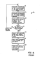
- the decision indicated by method step 87 is quite important to the process illustrated in Figure 5 and the quantities upon which that decision is made are initially calculated as part of the method step 71.
- the method step 71 is shown in detail in Figure 6.
- a loop of calculations is first performed for each of the read and write channels.
- a first step lll effectively counts the amount of data that will be stored at this given instant of time in the buffer 13 for one channel.
- An accumulator which starts at zero, is incremented by one if the amount of data falls below a particular threshold, which can be measured in either disk revolution time or number-of AU's in the buffer.
- a particular threshold which can be measured in either disk revolution time or number-of AU's in the buffer.
- a next step 113 is to take the mathematical reciprocal of the amount of data, commonly measured in number of AU's, in the channel. This reciprocal is added to a separate accumulator which starts at zero. The result, after all channels are reviewed, is a global urgency measure number in the accumulator that is large if the channels are generally empty, and small if they are large.
- a next step 115 is to count the number of read or write AU's that will be in the buffers for the channel being reviewed, and then ask, as represented by block 117, whether those items have been calculated for each channel. If not, the quantities calculated by the steps 111, 113 and 115 are again calculated for the next channel.
- a step 119 develops a single quantity which is compared with a threshold A in the decision 87 of the method of Figure 5 for making a single read or write calculation.
- the global urgency measured in the accumulator as a result of applying step 113 for each channel is independent of the number of channels employed.
- the same threshold A is used in the step 87 of Figure 5 no matter how many channels are utilized; and the method of calculating the global urgency according to step 113 of Figure 6 remains the same.
- the calculated number will be somewhat higher as the number of channels increases, this automatically provides a necessary safeguard since less variation in the number of AU's in each channel can be permitted as the number of channels goes up. That is, the amount of unbalance in the channels must be maintained within narrower limits as the number of channels goes up since the larger the number of channels, the greater the chance of running into a difficulty which will cause the read buffered data to run out for one channel.
- the accumulated local critical count developed by the calculation step 111 for each channel is then used to adjust upward the global urgency in step 119 if necessary to have a realistic number to compare with a single threshold A in accordance with the step 87 of Figure 5.
- the local critical count is less than two (that is, fewer than two channels have an amount of data less than the threshold)
- no adjustment is made in the global urgency.
- the local critical count is equal to or greater than two (two or more channels have little buffered data)
- a small fixed constant is added to the global urgency.
- the resulting quantity that is compared to threshold A is referred herein as the "urgency”.
- thresholds could be set for the local critical count and global urgency measure with which to compare the vaules accumulated by the respective steps 111 and 113, but it is more convenient to have a single threshold A, and thus a single comparison 87, by adjusting the number to be compared through a combination of the local critical count in the global urgency measure in the step 119 of Figure 6.
- a step 121 identifies the channel which has the least amount of data in the simulated buffer (and thus will so have in the buffer 13 when the transfer schedule is executed), channel 3 in the example of Figure 3A. This thus provides a default selection which is implemented, unless changed by subsequent processing to be described.
- a step 123 conversely, identifies the channel that will have the most write AU's in the buffer memory 13 if it is later decided to do a write, the oldest A U for the channel identified by the step 123 to then be written to disk.
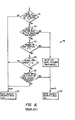
- step 93 the matter is again investigated in step 93, as illustrated in detail in Figure 7, to see whether the next in order data AU for some other channel would be more optimum to read rather than the emptiest channel identified in the step 123 of Figure 6.
- a decision 127 initially made depends upon whether any channel has less than a certain threshold B of buffered read data, measured in AU's. If so, the default read channel determined by step 123 of Figure 6 is not disturbed, the process moving directly by a path 128 to the end of block 93 processing.
- a step 129 then examines whether there are at least a certain number C of buffers that are free. If there are, processing proceeds to a step 131. If not, no further examination is made but rather the default read channel is maintained by the bypass path 128.
- the step 131 allows the chosen default read channel to remain if the seek time to read the next AU for that channel is less than a small threshold D. Since the goal of the processing 93 illustrated in Figure 7 is to reduce the seek time to reading the next AU from the disk if certain conditions of buffered data balance are satisfied, the condition 131 allows the inquiry to be terminated once it is discovered that the seek time for the priority data read AU is already expremely low. Under these conditions, the chances of improving that are low and so the inquiry is carried no further; the default read is selected to be performed at this place in the schedule.
- the processing goes into a loop wherein one of the other data channels is compared with the default data read channel selected by the step 123 of Figure 6. If this other channel is determined by this loop to be a better candidate for the next read, then it is substituted as the priority read for the default read previously determined, and the process is again repeated with yet another channel, comparing it to the new priority read channel. However, if the second cnannel turns out not to be any better than the priority read channel, then the process is repeated by comparing the third channel with the default priority read channel, and so forth.
- a step 133 determines whether the read of the new being compared with the priority channel has a disk access time of less than a threshold E. If not, then that channel's next read AU cannot be a candidate for replacing the default value and the process is ended through a path 135.
- a critical determination 137 is made as to whether the seek time of the second channel next read AU is less than that of the highest priority default read. If not, of course, there is no purpose in making any further inquiries, but if it is shorter, it is next determined whether the amount of data in the buffer 13 for the second read channel is much greater than that of the highest priority read channel. If so, then it is not desired to further that unbalance but rather the priority default read channel maintains its priority. If may further be desireable to require other combinations of reduced seek time and balance before changing the priority read to something else, as indicated by the step 141.
- a step 143 will cause the second channel data AU to be designated as the priority rather than the initial default value being so determined.
- the process is then repeated comparing yet another read channel if a step 145 determines that not all have been compared.
- the ending result is either that the read channel identified in step 123 of Figure 6 remains or that one having somewhat less access time has been substituted for it as the new priority read channel data AU.
- step 93 of Figure 5 To summarize how the determination is made in the step 93 of Figure 5, as illustrated in detail in Figure 7, fits into the overall picture, it will be noted that at point 97 of Figure 5 a decision has already been made in step 87 whether the path 89 is to be followed and the priority read determined by whichever one has the shortest access time, according to step 95, or alternatively by the patn 91 that determines the priority read data AU which tends to maintain a balanced condition among the buffered information for each channel, subject to whatever adjustment may be made in the step 93 because of particular circumstances.
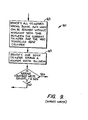
- the decision in the step 99 is then whether to cause that determined channel read data AU to be read or whether it is more appropriate to write an AU onto an empty portion of the disk, in the case where both reading and writing is occuring at the same time.
- Figure 8 illustrates the criteria in making that decision.
- a step 151 will cause such a read if there are no AU's within the buffer 13 to be written onto the disk. If there is at least one AU to be written, a step 153 then asks whether there is a read AU scheduled to be transferred from the disk into the buffer. If not, a step 155 is performed to decide where the AU shall be written, generally always being the cylinder that has the shortest access time from where the heads are currently located.
- a step 157 looks to the amount of free buffer memory 13. If the number of free buffers is less than some threshold F, then the writing step 155 is performed since it is of paramount importance to clear the buffer memory 13 to make room for additional read AU's. If the number of buffers is greater than the threshold F, then writing is not so critical and a next decision 159 is made as to whether the global read urgency is greater than a threshold G. If so, then reading is accomplished'since a high urgency represents an unbalanced situation among the read channels in the buffer 13. The threshold G is necessarily made to be slightly greater than the threshold A used in the initial decision step 87.
- step 161 determines whether a data AU within the buffer 13 can be written on a blank portion of a disk cylinder without adding any additional access time. If so, the highest priority data AU is written at that location where no additional time is necessary to do so. If not, then a read is accomplished according to step 101.
- a step 163 identifies all disk cylinders having space to write an AU and which can be accessed without increasing the disk head access time as it proceeds from its existing location to the cylinder containing the next data AU to be read. If it requires anything more than one-half revolution for the head to move from its existing cylinder to that containing the next designated priority read AU, there is a potential of having a blank space on a cylinder inbetween that could accept a write AU. For example, if a particular scheduled read requires one full revolution to access and there is a blank therebetween one-half revolution from each, that write and the next read can be done with the same total one revolution of access time.
- a step 165 will select one of those cylinders for a write.
- one of the possibilities for writing without additional access time which has the least amount of data on it will be selected by the step 165. If the number of buffered AU's in the buffer memory 13 for that particular channel from which the oldest is designated to be the highest priority write data AU, is greater than a threshold H, the AU will be written. If not, it shows that there are not that many AU's in the buffer memory 13 waiting to be written onto the disk and the reading 101 will be selected rather than the writing 103.
Landscapes
- Engineering & Computer Science (AREA)
- Signal Processing (AREA)
- Multimedia (AREA)
- Signal Processing For Digital Recording And Reproducing (AREA)
Applications Claiming Priority (2)
| Application Number | Priority Date | Filing Date | Title |
|---|---|---|---|
| US06/522,024 US4604687A (en) | 1983-08-11 | 1983-08-11 | Method and system for storing and retrieving multiple channel sampled data |
| US522024 | 1983-08-11 |
Publications (2)
| Publication Number | Publication Date |
|---|---|
| EP0133706A2 true EP0133706A2 (de) | 1985-03-06 |
| EP0133706A3 EP0133706A3 (de) | 1986-02-19 |
Family
ID=24079128
Family Applications (1)
| Application Number | Title | Priority Date | Filing Date |
|---|---|---|---|
| EP84109554A Withdrawn EP0133706A3 (de) | 1983-08-11 | 1984-08-10 | Verfahren und System zur Aufzeichnung und Rückgewinnung von in mehreren Kanälen abgetasteten Daten |
Country Status (4)
| Country | Link |
|---|---|
| US (1) | US4604687A (de) |
| EP (1) | EP0133706A3 (de) |
| JP (1) | JPS6089871A (de) |
| AU (1) | AU3179284A (de) |
Cited By (6)
| Publication number | Priority date | Publication date | Assignee | Title |
|---|---|---|---|---|
| DE3721080A1 (de) * | 1987-06-26 | 1989-01-19 | Thomson Brandt Gmbh | Verfahren zur abtastung und zur herstellung von plattenfoermigen optischen aufzeichnungstraegern, sowie plattenfoermiger optischer aufzeichnungstraeger |
| EP0266586A3 (de) * | 1986-11-03 | 1992-11-25 | International Business Machines Corporation | Verringern der Ansprechzeit für E/A-Anforderung durch Duplizierung der Daten |
| EP0552806A3 (en) * | 1992-01-23 | 1993-09-29 | Sharp Kabushiki Kaisha | Data recording and reproducing apparatus |
| EP0735763A1 (de) * | 1995-03-31 | 1996-10-02 | Sony Telecom (Europe) N.V. | System für Information auf Anfrage |
| EP0735538A1 (de) * | 1995-03-31 | 1996-10-02 | Sony Telecom (Europe) N.V. | Speichereinheit mit versetzter Aufzeichnung |
| US5687161A (en) * | 1993-06-03 | 1997-11-11 | Sega Enterprises, Ltd. | Apparatus and method for reproducing data from disk method for recording data on disk and disk |
Families Citing this family (19)
| Publication number | Priority date | Publication date | Assignee | Title |
|---|---|---|---|---|
| US5206943A (en) * | 1989-11-03 | 1993-04-27 | Compaq Computer Corporation | Disk array controller with parity capabilities |
| US5644786A (en) * | 1990-11-08 | 1997-07-01 | At&T Global Information Solutions Company | Method for scheduling the execution of disk I/O operations |
| US5163162A (en) * | 1990-11-14 | 1992-11-10 | Ibm Corporation | System and method for data recovery in multiple head assembly storage devices |
| EP0491463A2 (de) * | 1990-11-30 | 1992-06-24 | Matsushita Graphic Communication Systems, Inc. | Datenspeichersystem |
| JPH07191899A (ja) * | 1993-12-27 | 1995-07-28 | Hitachi Ltd | ファイル転送方法、データアクセス方法およびデータ書き込み方法 |
| US5712976A (en) * | 1994-09-08 | 1998-01-27 | International Business Machines Corporation | Video data streamer for simultaneously conveying same one or different ones of data blocks stored in storage node to each of plurality of communication nodes |
| EP0781432B1 (de) * | 1994-09-14 | 2006-12-06 | Intel Corporation | Editiersystem mit vorabzwischenspeicherung welches abfolgelisten verwendet |
| US5708793A (en) * | 1995-03-31 | 1998-01-13 | International Business Machines Corporation | Method and apparatus using address and read head location information to provide optimal operation of a disk system |
| US5787482A (en) * | 1995-07-31 | 1998-07-28 | Hewlett-Packard Company | Deadline driven disk scheduler method and apparatus with thresholded most urgent request queue scan window |
| US5991496A (en) * | 1995-11-29 | 1999-11-23 | Sony Corporation | Recording/reproducing apparatus and method thereof |
| JP3018966B2 (ja) * | 1995-12-01 | 2000-03-13 | 松下電器産業株式会社 | 記録再生装置 |
| US5737577A (en) * | 1996-08-12 | 1998-04-07 | Digital Video Systems, Inc. | Complementary block storage for breater minimumdata transfer rate |
| BR9906330A (pt) * | 1998-03-19 | 2000-07-04 | Koninkl Philips Electronics Nv | Equipamentos e processos para gravar e para editar um sinal de informação em tempo real, portadora para gravação tipo disco, e, equipamentos para simultaneamente gravar e reproduzir sinais de informação em tempo real, e para ler um sinal de informação em tempo real |
| US6195726B1 (en) * | 1999-03-24 | 2001-02-27 | Hewlett-Packard Company | Method and apparatus for performing patterned read and write operations |
| US6925426B1 (en) | 2000-02-22 | 2005-08-02 | Board Of Trustees Operating Michigan State University | Process for high fidelity sound recording and reproduction of musical sound |
| US7426568B2 (en) * | 2002-06-10 | 2008-09-16 | Lsi Corporation | Seek minimized recoverable streaming file system |
| WO2011112909A2 (en) | 2010-03-12 | 2011-09-15 | Sunrise Micro Devices, Inc. | Power efficient communications |
| US9601153B2 (en) * | 2014-06-30 | 2017-03-21 | Echostar Technologies L.L.C. | Systems and processes for efficiently storing and retrieving video content |
| CN116501709B (zh) * | 2023-06-25 | 2023-09-05 | 深圳市双合电气股份有限公司 | 基于iec61850数据服务功能的数据存储方法及设备 |
Family Cites Families (11)
| Publication number | Priority date | Publication date | Assignee | Title |
|---|---|---|---|---|
| US3337852A (en) * | 1964-06-05 | 1967-08-22 | Honeywell Inc | Information handling apparatus |
| BE756420A (fr) * | 1969-11-10 | 1971-03-01 | Ibm | Dispositif de transfert d'enregistrements |
| US4210941A (en) * | 1975-08-11 | 1980-07-01 | Casio Computer Co., Ltd. | Data-recording device |
| JPS52153714A (en) * | 1976-06-16 | 1977-12-21 | Matsushita Electric Ind Co Ltd | Filing device |
| US4270154A (en) * | 1978-03-01 | 1981-05-26 | Crawford John E | Head selection technique |
| US4241420A (en) * | 1978-11-01 | 1980-12-23 | Bank Computer Network Corporation | Disk data control |
| US4368513A (en) * | 1980-03-24 | 1983-01-11 | International Business Machines Corp. | Partial roll mode transfer for cyclic bulk memory |
| US4464689A (en) * | 1981-06-04 | 1984-08-07 | Education & Informations Systems, Inc. | Random access read/write unit |
| US4476526A (en) * | 1981-11-27 | 1984-10-09 | Storage Technology Corporation | Cache buffered memory subsystem |
| US4468730A (en) * | 1981-11-27 | 1984-08-28 | Storage Technology Corporation | Detection of sequential data stream for improvements in cache data storage |
| US4497023A (en) * | 1982-11-04 | 1985-01-29 | Lucasfilm Ltd. | Linked list of timed and untimed commands |
-
1983
- 1983-08-11 US US06/522,024 patent/US4604687A/en not_active Expired - Fee Related
-
1984
- 1984-08-10 JP JP59168732A patent/JPS6089871A/ja active Pending
- 1984-08-10 AU AU31792/84A patent/AU3179284A/en not_active Abandoned
- 1984-08-10 EP EP84109554A patent/EP0133706A3/de not_active Withdrawn
Cited By (11)
| Publication number | Priority date | Publication date | Assignee | Title |
|---|---|---|---|---|
| EP0266586A3 (de) * | 1986-11-03 | 1992-11-25 | International Business Machines Corporation | Verringern der Ansprechzeit für E/A-Anforderung durch Duplizierung der Daten |
| DE3721080A1 (de) * | 1987-06-26 | 1989-01-19 | Thomson Brandt Gmbh | Verfahren zur abtastung und zur herstellung von plattenfoermigen optischen aufzeichnungstraegern, sowie plattenfoermiger optischer aufzeichnungstraeger |
| EP0552806A3 (en) * | 1992-01-23 | 1993-09-29 | Sharp Kabushiki Kaisha | Data recording and reproducing apparatus |
| US5687161A (en) * | 1993-06-03 | 1997-11-11 | Sega Enterprises, Ltd. | Apparatus and method for reproducing data from disk method for recording data on disk and disk |
| US5745474A (en) * | 1993-06-03 | 1998-04-28 | Sega Enterprises, Ltd. | Apparatus and method for reproducing data from disk, method for recording data on disk and disk |
| EP0735763A1 (de) * | 1995-03-31 | 1996-10-02 | Sony Telecom (Europe) N.V. | System für Information auf Anfrage |
| EP0735538A1 (de) * | 1995-03-31 | 1996-10-02 | Sony Telecom (Europe) N.V. | Speichereinheit mit versetzter Aufzeichnung |
| WO1996030908A1 (en) * | 1995-03-31 | 1996-10-03 | Sony Europa B.V. | A storage medium unit and video service system having a stagger recording |
| WO1996031057A1 (en) * | 1995-03-31 | 1996-10-03 | Sony Europa B.V. | A system for information on demand |
| US6272281B1 (en) | 1995-03-31 | 2001-08-07 | Sony Europa B.V., | Storage medium unit and video service system having a stagger recording |
| USRE42905E1 (en) | 1995-03-31 | 2011-11-08 | Sony Europa B.V. | System for information on demand |
Also Published As
| Publication number | Publication date |
|---|---|
| AU3179284A (en) | 1985-02-14 |
| JPS6089871A (ja) | 1985-05-20 |
| US4604687A (en) | 1986-08-05 |
| EP0133706A3 (de) | 1986-02-19 |
Similar Documents
| Publication | Publication Date | Title |
|---|---|---|
| US4604687A (en) | Method and system for storing and retrieving multiple channel sampled data | |
| US5754882A (en) | Method for scheduling I/O transactions for a data storage system to maintain continuity of a plurality of full motion video streams | |
| US6499083B1 (en) | Disk-based storage system responsive to a direction-selection signal for autonomously controlling seeks in a sequence determined by the direction-selection signal and a locally-stored doubly linked list | |
| KR100343878B1 (ko) | 단일 디스크 드바이브내의 동일 자기디스크 매체를 서비스하는 2개의 액추에이터 사이의 태스크 할당 시스템 | |
| US7385781B1 (en) | Multi-arm disk drive system having interleaved read/write operations and method of controlling same | |
| RU2154309C2 (ru) | Способ и устройство для управления доступом к диску для записи данных | |
| US5765204A (en) | Method and apparatus for adaptive localization of frequently accessed, randomly addressed data | |
| EP0701198A1 (de) | Verfahren zum Betreiben einer Speichereinheitenmatrize | |
| JPH07302225A (ja) | 連続データ記録再生装置及びキャッシュ管理方法 | |
| US4972364A (en) | Memory disk accessing apparatus | |
| US4811280A (en) | Dual mode disk controller | |
| JPH0756688A (ja) | データ記憶装置 | |
| EP0732697A1 (de) | Wiedergabe- und Aufzeichnungsgerät für optische Platten | |
| US5774287A (en) | System and method employing buffering mechanism with interface for providing compatibility between recording formats | |
| US4797755A (en) | System and method for transferring data between a plurality of disks and a memory | |
| US6134586A (en) | Striping data across disk zones | |
| US6924953B2 (en) | Dual communication port sharing apparatus | |
| US6327641B1 (en) | Method of implementing a geometry per wedge (GPW) based headerless solution in a disk drive formatter and a computer program product incorporating the same | |
| JPS62243169A (ja) | 回転形記憶装置の制御方法 | |
| US6314232B2 (en) | Data allocation method, recording medium with data recorded by the method, and data server apparatus | |
| US6792504B2 (en) | Read on arrival scheme for a disc drive | |
| EP0266586A2 (de) | Verringern der Ansprechzeit für E/A-Anforderung durch Duplizierung der Daten | |
| EP0777392A3 (de) | Informationsspeichersteuerverfahren | |
| JPS61145767A (ja) | 磁気デイスク装置 | |
| JP2507497B2 (ja) | ディスク制御装置 |
Legal Events
| Date | Code | Title | Description |
|---|---|---|---|
| PUAI | Public reference made under article 153(3) epc to a published international application that has entered the european phase |
Free format text: ORIGINAL CODE: 0009012 |
|
| 17P | Request for examination filed |
Effective date: 19840810 |
|
| AK | Designated contracting states |
Designated state(s): AT BE CH DE FR GB IT LI LU NL SE |
|
| PUAL | Search report despatched |
Free format text: ORIGINAL CODE: 0009013 |
|
| AK | Designated contracting states |
Designated state(s): AT BE CH DE FR GB IT LI LU NL SE |
|
| STAA | Information on the status of an ep patent application or granted ep patent |
Free format text: STATUS: THE APPLICATION IS DEEMED TO BE WITHDRAWN |
|
| 18D | Application deemed to be withdrawn |
Effective date: 19880311 |
|
| RIN1 | Information on inventor provided before grant (corrected) |
Inventor name: ABBOTT, CURTIS W. |