EP0133710A2 - Rouleau sous-sol, compacteur - Google Patents
Rouleau sous-sol, compacteur Download PDFInfo
- Publication number
- EP0133710A2 EP0133710A2 EP84109611A EP84109611A EP0133710A2 EP 0133710 A2 EP0133710 A2 EP 0133710A2 EP 84109611 A EP84109611 A EP 84109611A EP 84109611 A EP84109611 A EP 84109611A EP 0133710 A2 EP0133710 A2 EP 0133710A2
- Authority
- EP
- European Patent Office
- Prior art keywords
- packer
- ring
- rings
- inner ring
- flange
- Prior art date
- Legal status (The legal status is an assumption and is not a legal conclusion. Google has not performed a legal analysis and makes no representation as to the accuracy of the status listed.)
- Granted
Links
Images

Classifications
-
- A—HUMAN NECESSITIES
- A01—AGRICULTURE; FORESTRY; ANIMAL HUSBANDRY; HUNTING; TRAPPING; FISHING
- A01B—SOIL WORKING IN AGRICULTURE OR FORESTRY; PARTS, DETAILS, OR ACCESSORIES OF AGRICULTURAL MACHINES OR IMPLEMENTS, IN GENERAL
- A01B29/00—Rollers
- A01B29/04—Rollers with non-smooth surface formed of rotatably-mounted rings or discs or with projections or ribs on the roller body; Land packers
- A01B29/041—Rollers with non-smooth surface formed of rotatably-mounted rings or discs or with projections or ribs on the roller body; Land packers of "Cambridge"-type, i.e. the soil-pressing rings being stacked on a shaft
Definitions
- the invention relates to an underground packer in an embodiment according to the preamble of claim 1.
- the inner ring part of the packer rings forms a hub body with an axial bore stretched through.
- Underground packers are also already known in which the packer rings essentially consist only of an outer ring part which has a number of connecting lugs distributed over the circumference on its inner circumference. These connecting lugs have axial bores, and for the mutual connection of adjacent packer rings, a number of spacer sleeves is used which corresponds to the number of connecting lugs and through which long sleeves are used Extend the clamping screws.
- Groups of three or more packer rings, which are connected to each other in this way without axles or shafts, receive flying support and support by means of a separate hub body, which can be connected to the attachment lugs of a packer ring arranged on the end face of the group via radially directed struts and on one end a packer axle or shaft can be placed.
- the packer axis or shaft is supported on a central longitudinal strut of the frame, carries a group of interconnected packer rings on each of its two free ends facing away from one another, and only penetrates the plane of the two packer rings of the packer ring group that are mounted on it by means of a hub body.
- the torsional stiffness and the strength and durability of the packer ring connections leave something to be desired, in particular due to the extensibility of the long clamping screws.
- the centering of the packer rings and their maintenance is difficult, since it is only brought about by the clamping screws and the holes for them.
- the invention has for its object to provide an underground packer of the type mentioned, in which interconnected packer rings form a particularly torsion-resistant assembly, are easy and precise to assemble and maintain a high connection strength.
- the underground packer according to the invention is characterized by the features specified in the characterizing part of claim 1. With regard to essential further refinements, reference is made to claims 2 to 8.
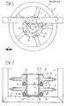
- the underground packer illustrated in FIGS. 1 and 2 consists in particular of a frame 1 which can be suitably attached to a towing vehicle and which is rectangular in shape and - based on the operating movement directions 2 of the device - is composed of external longitudinal struts 3 and transverse struts 4.
- the underground packer furthermore comprises a number of packer rings 5 arranged coaxially next to one another at a distance, each of which comprises an outer ring part 6 and an inner ring part 8 which is united therewith via approximately radial spokes 7.
- the parts 6, 7, 8 are preferably cast in one piece from metal.
- the inner ring parts 8 of the packer rings 5 have the cross-sectional shape of a U open to the outside, and the outer legs 9, 10 of this profile form flange rings with radially directed flange ring surfaces 11, 12.
- the inner ring part 8 is each provided with a centering ring groove 13, which is advantageously arranged on the inner edge of the flange ring surface 11.
- the other outer leg 10 of each inner part 8 is provided with a suitably designed, axially projecting centering ring shoulder 14 which engages in the centering ring groove of the inner part of a coaxially adjacent packer ring 5.
- axial bores 15 are provided, for example five, which run regularly over the Are distributed circumferentially.
- the mutually facing outer legs 9, 10 of the inner ring parts 8 of adjacent packer rings 5 are connected directly flush with one another by axial screws 16 which pass through the bores 15.
- These axial screws 16 are extremely short, easy to calculate and can be designed as standard parts.
- the mutual axial distance between the outer ring parts 6 of the packer rings 5 is determined in the embodiment according to FIGS. 1 and 2 by the axial width of the inner ring parts 8, i.e. the axial spacing of the respective flange ring surfaces 11, 12 from one another.
- a group of e.g. six packer rings connected to one another on their inner ring parts 8 in the manner described above form a working unit which is preferably supported on both sides in bearings 17 on both longitudinal struts 3 of the frame J.
- a connecting part 18 is provided at each end of the group of packer rings 5, only one of which is illustrated.
- Each of the two connecting parts 18 comprises a carrier part 19 with a stub shaft 20 fixed on one side to it, which is accommodated in the associated bearing 17.
- the carrier part 19 in turn forms a flange ring with a radial flange ring surface, which in turn is provided with a centering ring groove 13.
- the carrier part 19 is flush with the flange ring surface of the inner part 8 of the packer ring 5 lying outside in the group by axial screws 16 distributed over the circumference can be combined with the inner ring part 8 so that a group of packer rings 5 provided with two connecting parts forms a complete working unit which can be easily supported in the bearings 17 of the frame on both sides and freely rotatable about the central axis 21 of the group.
- the relatively short axial screws 16 are subject to only slight strains which are insignificant for the strength of the connection, so that a group of packer rings also offers a high connection strength.
- the embodiment according to FIGS. 3 and 4 corresponds in numerous parts to that according to FIGS. 1 and 2, and the corresponding parts have the same reference numerals.
- the frame 1 is provided with connections 22, 23 for lower and upper links of the three-point linkage of an agricultural tractor for the purpose of mounting the device, and it comprises an upper longitudinal cross member 24 with an upper pivot pin 25 for connecting a trailing additional device. It also includes support means 26 for transporting the additional device away.
- the packer rings 5 'differ from the packer rings 5 according to FIGS. 1 and 2 essentially by a different design of the inner ring parts 8', which have an approximately rectangular full cross section with radial, mutually parallel flange ring surfaces 11 ', 12'.
- the inner ring parts 8 'of adjacent packer rings 5' are each connected via a one-piece spacer ring body 27, and each spacer ring body 27 comprises two coaxial flange rings 29, 30 connected by a number, for example four, axial spacer webs 28, which on their outer radial flange ring surfaces in the region of the inner edge are provided with an axially protruding centering ring shoulders 14 'which engage in the circular central openings of the inner ring parts 8' of adjacent packer rings 5 '.
- the spacer ring body 27 can also be cast in one piece from metal. With their axial width, they determine the spacing of the packer rings 5 'from one another, and there is also the possibility of varying the spacing by choosing differently: wide packer ring body 27.
- connection parts 18 are used, corresponding to those in the embodiment according to FIGS.
- connecting parts can be provided, each of which in turn a carrier part 19 and instead of a stub shaft includes a hub sleeve united with this on one side. This can be placed on an axle or shaft journal, which is attached in a bearing of the central longitudinal strut.
- the connection of the carrier part 19 to that packing ring 5 or 5 1 of an overhung group is made by means of axial screws 16 in the manner already described.
- the embodiment according to FIGS. 3 and 4 also provides a high torsional rigidity for a group of interconnected packer rings 5 'with easy and permanent centering and a high strength of the connection which remains constant even under load.
Landscapes
- Life Sciences & Earth Sciences (AREA)
- Engineering & Computer Science (AREA)
- Mechanical Engineering (AREA)
- Soil Sciences (AREA)
- Environmental Sciences (AREA)
- Earth Drilling (AREA)
- Lining And Supports For Tunnels (AREA)
Applications Claiming Priority (2)
| Application Number | Priority Date | Filing Date | Title |
|---|---|---|---|
| DE19833330997 DE3330997A1 (de) | 1983-08-27 | 1983-08-27 | Untergrundpacker |
| DE3330997 | 1983-08-27 |
Publications (3)
| Publication Number | Publication Date |
|---|---|
| EP0133710A2 true EP0133710A2 (fr) | 1985-03-06 |
| EP0133710A3 EP0133710A3 (en) | 1986-06-18 |
| EP0133710B1 EP0133710B1 (fr) | 1989-09-13 |
Family
ID=6207638
Family Applications (1)
| Application Number | Title | Priority Date | Filing Date |
|---|---|---|---|
| EP84109611A Expired EP0133710B1 (fr) | 1983-08-27 | 1984-08-13 | Rouleau sous-sol, compacteur |
Country Status (2)
| Country | Link |
|---|---|
| EP (1) | EP0133710B1 (fr) |
| DE (1) | DE3330997A1 (fr) |
Cited By (10)
| Publication number | Priority date | Publication date | Assignee | Title |
|---|---|---|---|---|
| EP0223134A1 (fr) * | 1985-11-09 | 1987-05-27 | Amazonen-Werke H. Dreyer GmbH & Co. KG | Rouleau agraire |
| GB2301013A (en) * | 1995-05-24 | 1996-11-27 | Kenneth Frederick Taylor | Furrow press roller |
| RU2296445C2 (ru) * | 2005-01-11 | 2007-04-10 | Федеральное государственное образовательное учреждение высшего профессионального образования Ульяновская государственная сельскохозяйственная академия | Каток-гребнеобразователь |
| RU2347338C2 (ru) * | 2007-03-20 | 2009-02-27 | Федеральное государственное образовательное учреждение высшего профессионального образования Ульяновская государственная академия | Каток-гребнеобразователь |
| RU2487515C1 (ru) * | 2011-12-29 | 2013-07-20 | Федеральное государственное бюджетное образовательное учреждение высшего профессионального образования "Ульяновская государственная сельскохозяйственная академия" | Каток-гребнеобразователь |
| RU2509455C1 (ru) * | 2012-08-03 | 2014-03-20 | Федеральное государственное бюджетное образовательное учреждение высшего профессионального образования "Ульяновская государственная сельскохозяйственная академия имени П.А. Столыпина" | Каток-гребнеобразователь |
| RU2612438C1 (ru) * | 2016-01-11 | 2017-03-09 | Федеральное государственное бюджетное образовательное учреждение высшего образования "Ульяновская государственная сельскохозяйственная академия имени П.А. Столыпина" | Каток-гребнеобразователь |
| RU2612437C1 (ru) * | 2016-01-11 | 2017-03-09 | Федеральное государственное бюджетное образовательное учреждение высшего образования "Ульяновская государственная сельскохозяйственная академия имени П.А. Столыпина" | Каток-гребнеобразователь |
| RU2612424C1 (ru) * | 2016-01-11 | 2017-03-09 | Федеральное государственное бюджетное образовательное учреждение высшего образования "Ульяновская государственная сельскохозяйственная академия имени П.А. Столыпина" | Каток-гребнеобразователь |
| RU194330U1 (ru) * | 2019-08-30 | 2019-12-06 | Федеральное государственное бюджетное образовательное учреждение высшего образования "Ульяновский государственный аграрный университет имени П.А. Столыпина" | Каток-гребнеобразователь |
Families Citing this family (3)
| Publication number | Priority date | Publication date | Assignee | Title |
|---|---|---|---|---|
| RU2255451C1 (ru) * | 2004-02-03 | 2005-07-10 | Федеральное государственное образовательное учреждение высшего профессионального образования Ульяновская государственная сельскохозяйственная академия | Прикатывающий каток-гребнеобразователь |
| US9222707B2 (en) | 2013-02-14 | 2015-12-29 | Globalfoundries Inc. | Temperature stabilization in semiconductors using the magnetocaloric effect |
| RU2612436C1 (ru) * | 2016-01-11 | 2017-03-09 | Федеральное государственное бюджетное образовательное учреждение высшего образования "Ульяновская государственная сельскохозяйственная академия имени П.А. Столыпина" | Каток-гребнеобразователь |
Family Cites Families (9)
| Publication number | Priority date | Publication date | Assignee | Title |
|---|---|---|---|---|
| DE121268C (fr) * | ||||
| US1670838A (en) * | 1927-01-13 | 1928-05-22 | Ji Case Threshing Machine Co | Land-tilling implement |
| US2418937A (en) * | 1943-05-28 | 1947-04-15 | Brunt Mfg Company Van | Soil pulverizer and seeder |
| GB1070778A (en) * | 1964-11-18 | 1967-06-01 | Kabushi Kaisha Honda Gijutsu K | Improvements in or relating to agricultural machines |
| FR2264473A2 (en) * | 1974-03-19 | 1975-10-17 | Rousseau Joseph | Flail mower for mowing, ground clearance etc. - has circular flail support plates with double diametral folds |
| US4420048A (en) * | 1981-12-10 | 1983-12-13 | Deere & Company | Disk gang assembly |
| DE3208551C2 (de) * | 1982-03-10 | 1989-09-21 | Pflugfabrik Lemken Kg, 4234 Alpen | Packer oder walzenförmiges Gerät |
| DE8206584U1 (de) * | 1982-03-10 | 1983-10-20 | Pflugfabrik Lemken Kg, 4234 Alpen | Packer oder walzenfoermiges geraet |
| DE8230833U1 (de) * | 1982-11-04 | 1983-03-10 | H. Niemeyer Söhne GmbH & Co KG, 4446 Hörstel | Nachlaufgerät für Kehrpflüge |
-
1983
- 1983-08-27 DE DE19833330997 patent/DE3330997A1/de active Granted
-
1984
- 1984-08-13 EP EP84109611A patent/EP0133710B1/fr not_active Expired
Cited By (11)
| Publication number | Priority date | Publication date | Assignee | Title |
|---|---|---|---|---|
| EP0223134A1 (fr) * | 1985-11-09 | 1987-05-27 | Amazonen-Werke H. Dreyer GmbH & Co. KG | Rouleau agraire |
| GB2301013A (en) * | 1995-05-24 | 1996-11-27 | Kenneth Frederick Taylor | Furrow press roller |
| GB2301013B (en) * | 1995-05-24 | 1999-03-17 | Kenneth Frederick Taylor | Tools and tool arrangements for use in agriculture |
| RU2296445C2 (ru) * | 2005-01-11 | 2007-04-10 | Федеральное государственное образовательное учреждение высшего профессионального образования Ульяновская государственная сельскохозяйственная академия | Каток-гребнеобразователь |
| RU2347338C2 (ru) * | 2007-03-20 | 2009-02-27 | Федеральное государственное образовательное учреждение высшего профессионального образования Ульяновская государственная академия | Каток-гребнеобразователь |
| RU2487515C1 (ru) * | 2011-12-29 | 2013-07-20 | Федеральное государственное бюджетное образовательное учреждение высшего профессионального образования "Ульяновская государственная сельскохозяйственная академия" | Каток-гребнеобразователь |
| RU2509455C1 (ru) * | 2012-08-03 | 2014-03-20 | Федеральное государственное бюджетное образовательное учреждение высшего профессионального образования "Ульяновская государственная сельскохозяйственная академия имени П.А. Столыпина" | Каток-гребнеобразователь |
| RU2612438C1 (ru) * | 2016-01-11 | 2017-03-09 | Федеральное государственное бюджетное образовательное учреждение высшего образования "Ульяновская государственная сельскохозяйственная академия имени П.А. Столыпина" | Каток-гребнеобразователь |
| RU2612437C1 (ru) * | 2016-01-11 | 2017-03-09 | Федеральное государственное бюджетное образовательное учреждение высшего образования "Ульяновская государственная сельскохозяйственная академия имени П.А. Столыпина" | Каток-гребнеобразователь |
| RU2612424C1 (ru) * | 2016-01-11 | 2017-03-09 | Федеральное государственное бюджетное образовательное учреждение высшего образования "Ульяновская государственная сельскохозяйственная академия имени П.А. Столыпина" | Каток-гребнеобразователь |
| RU194330U1 (ru) * | 2019-08-30 | 2019-12-06 | Федеральное государственное бюджетное образовательное учреждение высшего образования "Ульяновский государственный аграрный университет имени П.А. Столыпина" | Каток-гребнеобразователь |
Also Published As
| Publication number | Publication date |
|---|---|
| DE3330997C2 (fr) | 1988-07-14 |
| EP0133710A3 (en) | 1986-06-18 |
| EP0133710B1 (fr) | 1989-09-13 |
| DE3330997A1 (de) | 1985-03-14 |
Similar Documents
| Publication | Publication Date | Title |
|---|---|---|
| DE2811906C2 (fr) | ||
| EP0133710B1 (fr) | Rouleau sous-sol, compacteur | |
| DE1525039B2 (de) | Kreuzfedergelenk und verfahren zu seiner herstellung | |
| DE3522700C2 (fr) | ||
| DE3048846C2 (de) | Kreuzgelenk | |
| DE3314322A1 (de) | Kreuzgelenk fuer eine gelenkwelle | |
| DE2835635C2 (fr) | ||
| DE2156745A1 (de) | Gefederte Spurketten Anordnung | |
| DE692007C (de) | Ausgleichgetriebe fuer Kraftfahrzeuge | |
| EP3649841B1 (fr) | Machine agricole destinée au traitement du sol | |
| DE68906782T2 (de) | Kraft- oder schleppfahrzeug mit unabhängigen doppelrädern. | |
| DE2344854B2 (de) | Radgewicht für Fahrzeuge | |
| DE3027702A1 (de) | Antriebsvorrichtung fuer ein geschlossenes deformierbares band | |
| EP3375272B1 (fr) | Rouleaux de compactage pour le travail du sol | |
| DE19939729C2 (de) | Antriebsanordnung | |
| DE2126701A1 (de) | Rad-Aufhängungssysteme | |
| DE1000698B (de) | Mehrachsfahrzeug | |
| DE1025279B (de) | Ausgleichgetriebe fuer Kraftfahrzeuge | |
| DE1851815U (de) | Elastische anschlussgruppe, besonders fuer stossdaempfer in kraftfahrzeugen u. dgl. | |
| DE4205653A1 (de) | Kreuzgelenk | |
| EP0068477B1 (fr) | Bielle de support, ou bielle analogue en forme de tube, spécialement pour machines agricoles | |
| DE1103375B (de) | Bremsscheibe, insbesondere fuer Schienenfahrzeuge | |
| EP0134032B1 (fr) | Rouleau sous-sol compacteur | |
| DE815873C (de) | Elastisches Lager | |
| DE10107976B4 (de) | Lagerkombination |
Legal Events
| Date | Code | Title | Description |
|---|---|---|---|
| PUAI | Public reference made under article 153(3) epc to a published international application that has entered the european phase |
Free format text: ORIGINAL CODE: 0009012 |
|
| AK | Designated contracting states |
Designated state(s): FR GB NL |
|
| PUAL | Search report despatched |
Free format text: ORIGINAL CODE: 0009013 |
|
| AK | Designated contracting states |
Kind code of ref document: A3 Designated state(s): FR GB NL |
|
| 17P | Request for examination filed |
Effective date: 19860610 |
|
| 17Q | First examination report despatched |
Effective date: 19870810 |
|
| GRAA | (expected) grant |
Free format text: ORIGINAL CODE: 0009210 |
|
| AK | Designated contracting states |
Kind code of ref document: B1 Designated state(s): FR GB NL |
|
| ET | Fr: translation filed | ||
| GBT | Gb: translation of ep patent filed (gb section 77(6)(a)/1977) | ||
| PLBE | No opposition filed within time limit |
Free format text: ORIGINAL CODE: 0009261 |
|
| STAA | Information on the status of an ep patent application or granted ep patent |
Free format text: STATUS: NO OPPOSITION FILED WITHIN TIME LIMIT |
|
| 26N | No opposition filed | ||
| PGFP | Annual fee paid to national office [announced via postgrant information from national office to epo] |
Ref country code: GB Payment date: 19910723 Year of fee payment: 8 |
|
| PGFP | Annual fee paid to national office [announced via postgrant information from national office to epo] |
Ref country code: NL Payment date: 19910831 Year of fee payment: 8 |
|
| PG25 | Lapsed in a contracting state [announced via postgrant information from national office to epo] |
Ref country code: GB Effective date: 19920813 |
|
| PG25 | Lapsed in a contracting state [announced via postgrant information from national office to epo] |
Ref country code: NL Effective date: 19930301 |
|
| GBPC | Gb: european patent ceased through non-payment of renewal fee |
Effective date: 19920813 |
|
| NLV4 | Nl: lapsed or anulled due to non-payment of the annual fee | ||
| PGFP | Annual fee paid to national office [announced via postgrant information from national office to epo] |
Ref country code: FR Payment date: 19950831 Year of fee payment: 12 |
|
| PG25 | Lapsed in a contracting state [announced via postgrant information from national office to epo] |
Ref country code: FR Effective date: 19970430 |
|
| REG | Reference to a national code |
Ref country code: FR Ref legal event code: ST |