EP0133824B1 - Modulare Anschlussvorrichtung für Fernsprechverteiler - Google Patents
Modulare Anschlussvorrichtung für Fernsprechverteiler Download PDFInfo
- Publication number
- EP0133824B1 EP0133824B1 EP84401176A EP84401176A EP0133824B1 EP 0133824 B1 EP0133824 B1 EP 0133824B1 EP 84401176 A EP84401176 A EP 84401176A EP 84401176 A EP84401176 A EP 84401176A EP 0133824 B1 EP0133824 B1 EP 0133824B1
- Authority
- EP
- European Patent Office
- Prior art keywords
- module
- modules
- front face
- rail
- fixing
- Prior art date
- Legal status (The legal status is an assumption and is not a legal conclusion. Google has not performed a legal analysis and makes no representation as to the accuracy of the status listed.)
- Expired
Links
- 230000000007 visual effect Effects 0.000 claims 1
- 238000009434 installation Methods 0.000 abstract description 2
- 241001631457 Cannula Species 0.000 description 4
- 241000446313 Lamella Species 0.000 description 2
- 238000012986 modification Methods 0.000 description 2
- 230000004048 modification Effects 0.000 description 2
- 241000656145 Thyrsites atun Species 0.000 description 1
- 230000006978 adaptation Effects 0.000 description 1
- XAGFODPZIPBFFR-UHFFFAOYSA-N aluminium Chemical compound [Al] XAGFODPZIPBFFR-UHFFFAOYSA-N 0.000 description 1
- 229910052782 aluminium Inorganic materials 0.000 description 1
- 238000004519 manufacturing process Methods 0.000 description 1
- 238000000034 method Methods 0.000 description 1
- 239000002991 molded plastic Substances 0.000 description 1
- 238000002360 preparation method Methods 0.000 description 1
- 238000003825 pressing Methods 0.000 description 1
- 230000001681 protective effect Effects 0.000 description 1
- 230000001012 protector Effects 0.000 description 1
- 238000012800 visualization Methods 0.000 description 1
Images


Classifications
-
- H—ELECTRICITY
- H04—ELECTRIC COMMUNICATION TECHNIQUE
- H04Q—SELECTING
- H04Q1/00—Details of selecting apparatus or arrangements
- H04Q1/02—Constructional details
- H04Q1/14—Distribution frames
- H04Q1/142—Terminal blocks for distribution frames
-
- H—ELECTRICITY
- H04—ELECTRIC COMMUNICATION TECHNIQUE
- H04Q—SELECTING
- H04Q1/00—Details of selecting apparatus or arrangements
- H04Q1/02—Constructional details
- H04Q1/14—Distribution frames
- H04Q1/149—Wireguides in connector blocks
-
- H—ELECTRICITY
- H04—ELECTRIC COMMUNICATION TECHNIQUE
- H04Q—SELECTING
- H04Q2201/00—Constructional details of selecting arrangements
- H04Q2201/18—Rails
Definitions
- the subject of the present invention is a modular connection system or device for a telephone distributor, of the type comprising vertical bars to which connection elements can be fixed, which may constitute a strip or cable head part.
- a distributor is already known (European patent 74 898) comprising a profile, provided with various organic elements such as connector blocks of a first type and connector blocks of a second type, rings, etc.
- This connector allows most operations to be carried out in the factory.
- the method of use includes mounting organic elements on a profile, then placing the profile provided with these elements.
- the subject of the invention is a telephone distributor, the assembly of which on site, and the modifications are simple and quick operations to execute.
- the subject of the present invention is a modular connection device for a telephone distributor, comprising vertical bars on which connection elements or modules can be fixed, of generally rectangular shape, which can constitute a strip or cable head part, each bar vertical having sufficient strength to directly receive and support modules, and is advantageously constituted by a profile 2, 40 forming a self-supporting rail, characterized in that the profile has a front face provided for receiving the modules, in that the modules are fixed in place by at least three connections of two different types arranged in staggered rows, at least one connection by pressing against a surface of the front face and at least one connection by hooking by means of a hook applied to a surface opposite to the front face, the profile having at least three longitudinal zones for fixing modules, including at least one support area on the front face and at least one attachment area on a surface opposite the front face.
- each module comprises a wire guide on at least one adjacent side or exit face of the wires.
- the wire guide is constituted, in a manner known per se, by a ring integral with the module, split ring, preferably by an oblique slot.
- the means for fixing each module on a self-supporting rail are advantageously constituted by two support feet and two traction hooks forming an integral part of the body of the module, the assembly having a certain elasticity , allowing snap-in mounting and dismantling.
- One hook can be flexible and the other reinforced hook can be used as a hinge.
- the profile, or self-supporting rail may include fixing cannulas for rings, hooks or the like. Several rails are linked at the two ends, high and low, to form the frame of the distributor.
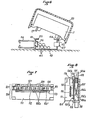
- a module 1 mounted on a self-supporting rail 2. It is a module having two double walls: it has in each face channels 3 in the shape of a butt making connections between a row of contacts on the upper face and a corresponding side face, for passing wires 4, 5 there.
- a module is shown by way of example comprising a self-stripping contact 7, label holders 8, a contact support 9, a base 10, double walls with grommet 11, a breaking element 12.
- the module For its attachment to the support 2, the module comprises two support feet 15, 16 and two hooks 17, 18.
- the hook 17 is relatively flexible, to allow the snap-fastening, while the hook 18 is reinforced by a veil 19 , which allows it to be used as a hinge to place it on the rail or remove it, as shown in Figure 4.
- the module comprises on the projecting side of the face where the grommet channels open, a thread guide 21, 22, in which the wires 4, 5 are passed, respectively.
- each thread guide can be made in the form of a ring with an oblique slot for allow the establishment of the wire.
- the wires can thus be placed in a desired arrangement, and kept in this arrangement without the need for other elements than the module and the support rail.
- a protective cover 20 which can cover a series of modules, and snaps by its edges 20a, 20b on laterally projecting points of the module, for example on the wire guide rings 21, 22.
- the protector 20 is made of molded plastic, with sufficient flexibility to have an easy snap-on. It can be used for carrying labels or indications concerning the modules it protects.
- FIG. 5 A first example of a self-supporting rail 2 is shown in FIG. 5. It has lateral wings 31, 32, under the edges 31a, 32a from which the hooks 17, 18 of the modules are fixed, and against the flat surface from which come apply the support feet 15, 16 of the modules.
- the rail advantageously has longitudinal grooves 33, 34, 35, 36 whose edges are brought together to form fixing cannulas. It is thus possible to fix directly on this rail a hook 50 in which holes 51, 52 have been drilled for fixing in the cannulas 33, 34 for example.
- the cannulas allow to receive screws or bolts of various dimensions. Thus, it is possible with such profiles to directly constitute a distributor. Simply link the top and bottom profiles to horizontal supports.
- Figure 6 shows in cross section a second example of self-supporting rail 40.
- the section as a whole has the shape of a U with flanges 41, 42 for receiving the hooks 17, 18 of a module 1 and strips planes 43, 44 to receive the support feet 15, 16 of the module 1.
- the U-shape of the section allows cables 45 to be passed.
- a longitudinal groove 46 is shown, making it possible to fix for example a hook 53.
- Several grooves can be planned. It is possible with a simple tool to drill holes in the wall of the rail 40 to accommodate or fix auxiliary elements such as a connector 47.
- FIGS. 7 and 8 show a cut-off module 101 and an auxiliary module 104.
- the cut-off module 101 consists of a box 105 of planar shape, with two planar faces 102a, 102b.
- the housing 105 In the housing 105, are trapped sixteen pairs of pins 106, 106 'arranged in pairs facing each other, to form two rows defining sixteen pairs of contacts (eight double pairs).
- the box is designed to be fixed on a support rail (not shown) in the same way as the previous modules.
- the free ends 106a, 106'a of the pins emerge from the housing on the side opposite the self-supporting rail.
- Each pin consists of an elastic strip having an outer end 106a, 106'a and an inner end 106b, 106'b.
- a lamella 106 and a lamella 106 'opposite are shaped and held in the housing 105 so that the inner ends 106b, 106'b are applied elastically against each other, in the extension of a cutoff well 107.
- the introduction of a cut-off jumper in a well 107 separates the ends 106b, 106'b from one another and also forms an insulating screen between the two.
- Wire passage channels 109, 109 ′ can join the upper face to a lateral face.
- an auxiliary module 104 comprising a box 111 of flat and rectangular shape to a breaking module with a printed board 112 forming one of the walls of the auxiliary module, the upper edge of which is released by means of an opening. 113.
- the outer end 106'a of each spindle suitably folded and engaged in the elongated opening 113 ensures the electrical contact between the pike itself and a contact provided on the edge of the card, thus that the attachment of the auxiliary module against the cut-off module, the card 112 being kept applied against the face 102b of the cut-off module.
- the auxiliary module 104 thus fixed to the cut-off module 101 can be mounted with the latter on a support rail (not shown). It accommodates electronic components 115 (surge voltages, resistors, diodes, etc.) mounted on a printed circuit on the card 112.
- the box can be pierced to reveal lamps or diodes 116 allowing visualizations or even a member such as a push button, a socket for receiving a plug-in member.
- the auxiliary module can be fixed to the self-supporting rail, like an ordinary module.
- the two outer ends 106a, 106'a can be straight on the outside, the end 106'a can be connected to the card by a wire.
- the dimensions of the auxiliary module will advantageously be chosen so that its thickness is equal to that of a module or is a multiple, for example twice that of the cut-off module.
- the cut-off zone (entry of wells 107) is always available for the cut-off jumper.
- the front (upper side or opposite to the support rail) allows marking to be affixed.
- the self-supporting rail 2 or 40 is an extruded aluminum profile, which reduces the manufacturing cost and allows in practice all the sections, depending on the foreseeable loads.
- the constant section of the profile over its entire length, without any notch, makes it possible to fix a module at any location, without having to take any step into account.
- Modules of various thicknesses can be placed, multiple or not of the thickness of an ordinary module.
Landscapes
- Engineering & Computer Science (AREA)
- Computer Networks & Wireless Communication (AREA)
- Structure Of Telephone Exchanges (AREA)
- Installation Of Indoor Wiring (AREA)
- Telephone Function (AREA)
- Connector Housings Or Holding Contact Members (AREA)
- Telephone Set Structure (AREA)
Claims (7)
Priority Applications (1)
| Application Number | Priority Date | Filing Date | Title |
|---|---|---|---|
| AT84401176T ATE34500T1 (de) | 1983-07-29 | 1984-06-06 | Modulare anschlussvorrichtung fuer fernsprechverteiler. |
Applications Claiming Priority (2)
| Application Number | Priority Date | Filing Date | Title |
|---|---|---|---|
| FR8312516A FR2550042B1 (fr) | 1983-07-29 | 1983-07-29 | Dispositif de raccordement modulaire pour repartiteur telephonique |
| FR8312516 | 1983-07-29 |
Publications (2)
| Publication Number | Publication Date |
|---|---|
| EP0133824A1 EP0133824A1 (de) | 1985-03-06 |
| EP0133824B1 true EP0133824B1 (de) | 1988-05-18 |
Family
ID=9291217
Family Applications (1)
| Application Number | Title | Priority Date | Filing Date |
|---|---|---|---|
| EP84401176A Expired EP0133824B1 (de) | 1983-07-29 | 1984-06-06 | Modulare Anschlussvorrichtung für Fernsprechverteiler |
Country Status (6)
| Country | Link |
|---|---|
| US (1) | US4581489A (de) |
| EP (1) | EP0133824B1 (de) |
| JP (1) | JPS6043991A (de) |
| AT (1) | ATE34500T1 (de) |
| DE (1) | DE3471422D1 (de) |
| FR (1) | FR2550042B1 (de) |
Families Citing this family (27)
| Publication number | Priority date | Publication date | Assignee | Title |
|---|---|---|---|---|
| DE3572079D1 (en) * | 1985-02-02 | 1989-09-07 | Square D Starkstrom Gmbh | Rapid-mounting device for circuit breakers |
| US4840568A (en) * | 1987-03-31 | 1989-06-20 | Adc Telecommunications, Inc. | Jack assembly |
| US4763226A (en) * | 1987-05-22 | 1988-08-09 | Northern Telecom Limited | Connecting blocks and mounting arrangements for telephone systems |
| DE8711332U1 (de) * | 1987-08-20 | 1987-10-29 | Siemens AG, 1000 Berlin und 8000 München | Trägerelement für mehrere daran zu befestigende Verteilerleisten |
| DE3728368C1 (de) * | 1987-08-21 | 1988-11-10 | Krone Ag | Vorrichtung zur Halterung von Anschlussleisten der Fernmeldetechnik |
| US4904211A (en) * | 1989-04-03 | 1990-02-27 | Porta Systems Corp. | Frame cradle for telephone connector blocks |
| JPH0345292A (ja) * | 1989-07-14 | 1991-02-26 | Agency Of Ind Science & Technol | 縫代制御装置 |
| JPH03112075A (ja) * | 1989-09-27 | 1991-05-13 | Terada Denki Seisakusho:Kk | 端子板 |
| EP0491245B1 (de) * | 1990-12-19 | 1995-11-08 | Siemens Aktiengesellschaft | Trägereinheit für Anschlussleisten eines Verteilers in Telekommunikationsanlagen |
| US5380226A (en) * | 1992-11-10 | 1995-01-10 | Burndy Corporation | Electrical terminal block |
| US5356316A (en) * | 1992-11-10 | 1994-10-18 | Burndy Corporation | Combined electrical connector mounting track and grounding connector assembly |
| US5374202A (en) * | 1992-11-10 | 1994-12-20 | Burndy Corporation | Electrical connector spacer |
| US5320564A (en) * | 1992-11-10 | 1994-06-14 | Burndy Corporation | Track connection system for electrical connectors |
| JP2530591Y2 (ja) * | 1993-06-22 | 1997-03-26 | 沖電気工業株式会社 | 交換機の主配線盤用架におけるケーブルの固定構造 |
| DE59410263D1 (de) * | 1993-09-06 | 2003-05-08 | Quante Ag | Verteilereinrichtung für Fernmelde-, Signal-, Steuerkabel od. dgl. |
| FR2719180B1 (fr) * | 1994-04-20 | 1996-07-12 | Jacques Nozick | Châssis de répartiteur. |
| US5802168A (en) * | 1996-01-26 | 1998-09-01 | Conklin Instrument Corp. | ISDN capacity expansion for remote terminal sites |
| DE29903518U1 (de) * | 1999-02-26 | 1999-05-27 | Quante Ag, 42109 Wuppertal | Verteilereinrichtung |
| DE20203912U1 (de) * | 2002-03-11 | 2003-07-17 | 3M Innovative Properties Co., St. Paul, Minn. | Anschlußmodul der Telekommunikationstechnik und Kombination mit einem Anschlußmodul |
| JP2003308902A (ja) * | 2002-04-12 | 2003-10-31 | Omron Corp | 電気機器接続ターミナル |
| EP1679766A1 (de) * | 2005-01-10 | 2006-07-12 | 3M Innovative Properties Company | Drahtführungsplatte und Zusammenbau sowie ein Telekommunikationsmodul mit wenigtens einer Drahtführungsplatte |
| US20070082522A1 (en) * | 2005-10-11 | 2007-04-12 | Pierre Bonvallat | Carrier and an assembly including a carrier and a telecommunications module |
| US7317177B2 (en) * | 2006-04-24 | 2008-01-08 | Inductoheat, Inc. | Electric induction heat treatment of an end of tubular material |
| HRP20100098T1 (hr) | 2006-07-25 | 2010-04-30 | Adc Gmbh | Spojni blok |
| NZ572640A (en) | 2006-07-25 | 2011-10-28 | Adc Gmbh | Connector block |
| AU313574S (en) | 2006-07-25 | 2007-04-10 | Tyco Electronics Services Gmbh | Connector block |
| PL4354665T3 (pl) * | 2022-10-10 | 2025-03-31 | Danfoss A/S | System montażowy do montowania jednostki górnej na module sterownika elektronicznego |
Family Cites Families (18)
| Publication number | Priority date | Publication date | Assignee | Title |
|---|---|---|---|---|
| US3753216A (en) * | 1971-10-14 | 1973-08-14 | Amp Inc | High voltage terminal strip |
| US3756637A (en) * | 1971-12-03 | 1973-09-04 | Volt Quebec Lab | Snap track |
| US3850301A (en) * | 1973-03-14 | 1974-11-26 | Mc Donnell Douglas Corp | Mount for electrical junction blocks |
| FR2223937B1 (de) * | 1973-03-29 | 1978-03-24 | Telemecanique Electrique | |
| IT1058331B (it) * | 1975-12-19 | 1982-04-10 | Sits Soc It Telecom Siemens | Ripartitore modulatore con prese di sezionamento |
| DE2628489B2 (de) * | 1976-06-25 | 1978-07-20 | Siemens Ag, 1000 Berlin Und 8000 Muenchen | Aufnahmevorrichtung für Geräteeinheiten der elektrischen Nachrichtenübertragungstechnik |
| DE2711783C3 (de) * | 1977-03-17 | 1980-10-30 | Siemens Ag, 1000 Berlin Und 8000 Muenchen | NF-Verteilergestell |
| DE2834708C3 (de) * | 1978-08-08 | 1981-02-19 | Siemens Ag, 1000 Berlin Und 8000 Muenchen | Verteilergestell für Einrichtungen der Nachrichtenübertragungstechnik |
| FR2443758A1 (fr) * | 1978-12-08 | 1980-07-04 | Lissillour Albert | Equipement de protection des lignes d'une tete de cable d'un central notamment telephonique |
| US4204095A (en) * | 1978-12-28 | 1980-05-20 | Porta Systems Corp. | Telephone main distributing frame |
| FR2446040A1 (fr) * | 1979-01-03 | 1980-08-01 | Nozick Jacques | Repartiteur de central telephonique |
| US4366528A (en) * | 1980-12-23 | 1982-12-28 | Gte Products Corporation | Switchboard housing apparatus |
| DE3130133C2 (de) * | 1981-07-30 | 1986-09-25 | Siemens AG, 1000 Berlin und 8000 München | Verteilerleiste für Fernsprechvermittlungsanlagen |
| US4442476A (en) * | 1981-08-17 | 1984-04-10 | Westinghouse Electric Corp. | Versatile printed circuit board termination rack |
| US4371757A (en) * | 1981-08-21 | 1983-02-01 | Northern Telecom Limited | Enclosure for outdoor cross-connect system for telecommunications |
| FR2512619A1 (fr) * | 1981-09-10 | 1983-03-11 | Boga Sa | Colonne de repartiteur telephonique, profile pour une telle colonne, repartiteur telephonique et procede de montage d'un tel repartiteur |
| EP0079805B1 (de) * | 1981-11-18 | 1986-03-19 | Fujitsu Limited | Gehäuse für Fernmeldeeinrichtung |
| US4496057A (en) * | 1982-07-26 | 1985-01-29 | Fujitsu Limited | Rack structure for mounting a communication apparatus |
-
1983
- 1983-07-29 FR FR8312516A patent/FR2550042B1/fr not_active Expired
-
1984
- 1984-06-06 DE DE8484401176T patent/DE3471422D1/de not_active Expired
- 1984-06-06 AT AT84401176T patent/ATE34500T1/de not_active IP Right Cessation
- 1984-06-06 EP EP84401176A patent/EP0133824B1/de not_active Expired
- 1984-06-15 JP JP59123510A patent/JPS6043991A/ja active Pending
- 1984-06-18 US US06/621,755 patent/US4581489A/en not_active Expired - Fee Related
Also Published As
| Publication number | Publication date |
|---|---|
| FR2550042A1 (fr) | 1985-02-01 |
| EP0133824A1 (de) | 1985-03-06 |
| US4581489A (en) | 1986-04-08 |
| FR2550042B1 (fr) | 1985-11-22 |
| JPS6043991A (ja) | 1985-03-08 |
| DE3471422D1 (en) | 1988-06-23 |
| ATE34500T1 (de) | 1988-06-15 |
Similar Documents
| Publication | Publication Date | Title |
|---|---|---|
| EP0133824A1 (de) | Modulare Anschlussvorrichtung für Fernsprechverteiler | |
| EP0237409B1 (de) | Vorrichtung zum Aufhängen und Beleuchten von Gegenständen | |
| CN101421853A (zh) | 用于扁平导体的电连接装置 | |
| CA2031007A1 (fr) | Cadre pour meuble de bureau modulable dont les conducteurs electriques sont loges dans le plateau | |
| EP0859526A1 (de) | Modulare Verteilerleiste für ein Datennetz | |
| CA2105311A1 (fr) | Dispositif de support et d'alimentation pour un eclairage a tres basse tension | |
| FR2711019A1 (fr) | Armoire à appareils. | |
| EP0734099B1 (de) | Modulare elektrische Reihenklemmenanordnung | |
| FR2526595A1 (fr) | Structure de socle ou plinthe pour la distribution d'energie electrique ou pour d'autres services similaires dans des locaux a usage civil | |
| FR2823602A1 (fr) | Ensemble de montage de connecteur electrique | |
| FR2590736A1 (fr) | Perfectionnement aux structures de supportage cables electriques, canalisations et similaires | |
| FR2519222A1 (fr) | Dispositif de raccordement polyvalent pour repartiteur de central telephonique | |
| EP0315558B1 (de) | Elektrifizierte Gleitschiene für eine bewegbare elektrische Steckdose | |
| FR2727577A1 (fr) | Colonne technique adaptee a supporter des appareils, de commande et/ou de distribution, connectes a des cables, et a recevoir lesdits cables | |
| EP0646987B1 (de) | Verbindungsvorrichtung mit verbesserter Zuverlässigkeit | |
| EP0517619B1 (de) | Elektrische Anschlussleiste | |
| FR2582451A1 (fr) | Connecteur-barrette de raccordement pour des appareils modulaires | |
| FR2662549A1 (fr) | Dispositif d'interconnexion pour reglette de raccordement electrique ou analogue. | |
| FR2612031A1 (fr) | Dispositif de passage de fils conducteurs et repartiteur telephonique comportant un tel dispositif | |
| EP0074898B1 (de) | Fernsprechverteilerleiste, Profil für diese Leiste und Fernsprechverteiler | |
| WO1996019019A1 (fr) | Fiche electrique du type fiche anglaise | |
| FR2461432A1 (fr) | Systeme d'interconnexion d'une pluralite de fils isoles | |
| DE202006006183U1 (de) | Möbel | |
| FR2538208A1 (fr) | Dispositif auxiliaire pour modules a coupure | |
| EP3672002A1 (de) | Stromverteilungskasten |
Legal Events
| Date | Code | Title | Description |
|---|---|---|---|
| PUAI | Public reference made under article 153(3) epc to a published international application that has entered the european phase |
Free format text: ORIGINAL CODE: 0009012 |
|
| AK | Designated contracting states |
Designated state(s): AT BE CH DE FR GB IT LI LU NL SE |
|
| 17P | Request for examination filed |
Effective date: 19850903 |
|
| 17Q | First examination report despatched |
Effective date: 19860718 |
|
| D17Q | First examination report despatched (deleted) | ||
| GRAA | (expected) grant |
Free format text: ORIGINAL CODE: 0009210 |
|
| AK | Designated contracting states |
Kind code of ref document: B1 Designated state(s): AT BE CH DE FR GB IT LI LU NL SE |
|
| REF | Corresponds to: |
Ref document number: 34500 Country of ref document: AT Date of ref document: 19880615 Kind code of ref document: T |
|
| REF | Corresponds to: |
Ref document number: 3471422 Country of ref document: DE Date of ref document: 19880623 |
|
| GBT | Gb: translation of ep patent filed (gb section 77(6)(a)/1977) | ||
| 111L | Licence recorded |
Free format text: 0100 MARS ALCATEL |
|
| REG | Reference to a national code |
Ref country code: CH Ref legal event code: PLI Owner name: MARS ALCATEL |
|
| ITF | It: translation for a ep patent filed | ||
| PLBE | No opposition filed within time limit |
Free format text: ORIGINAL CODE: 0009261 |
|
| STAA | Information on the status of an ep patent application or granted ep patent |
Free format text: STATUS: NO OPPOSITION FILED WITHIN TIME LIMIT |
|
| 26N | No opposition filed | ||
| REG | Reference to a national code |
Ref country code: FR Ref legal event code: AM |
|
| ITTA | It: last paid annual fee | ||
| REG | Reference to a national code |
Ref country code: FR Ref legal event code: DJ |
|
| REG | Reference to a national code |
Ref country code: FR Ref legal event code: CL |
|
| ITPR | It: changes in ownership of a european patent |
Owner name: TRASFERIMENTO TITOLARITA' PER SENTENZA;CTM COMPAGN |
|
| REG | Reference to a national code |
Ref country code: FR Ref legal event code: CL Ref country code: FR Ref legal event code: CA |
|
| PGFP | Annual fee paid to national office [announced via postgrant information from national office to epo] |
Ref country code: GB Payment date: 19940602 Year of fee payment: 11 |
|
| PGFP | Annual fee paid to national office [announced via postgrant information from national office to epo] |
Ref country code: SE Payment date: 19940607 Year of fee payment: 11 |
|
| PGFP | Annual fee paid to national office [announced via postgrant information from national office to epo] |
Ref country code: AT Payment date: 19940621 Year of fee payment: 11 |
|
| PGFP | Annual fee paid to national office [announced via postgrant information from national office to epo] |
Ref country code: CH Payment date: 19940627 Year of fee payment: 11 |
|
| PGFP | Annual fee paid to national office [announced via postgrant information from national office to epo] |
Ref country code: NL Payment date: 19940630 Year of fee payment: 11 Ref country code: LU Payment date: 19940630 Year of fee payment: 11 |
|
| PGFP | Annual fee paid to national office [announced via postgrant information from national office to epo] |
Ref country code: BE Payment date: 19940713 Year of fee payment: 11 |
|
| EPTA | Lu: last paid annual fee | ||
| PGFP | Annual fee paid to national office [announced via postgrant information from national office to epo] |
Ref country code: DE Payment date: 19940811 Year of fee payment: 11 |
|
| EAL | Se: european patent in force in sweden |
Ref document number: 84401176.7 |
|
| PG25 | Lapsed in a contracting state [announced via postgrant information from national office to epo] |
Ref country code: LU Free format text: LAPSE BECAUSE OF NON-PAYMENT OF DUE FEES Effective date: 19950606 Ref country code: GB Effective date: 19950606 Ref country code: AT Effective date: 19950606 |
|
| PG25 | Lapsed in a contracting state [announced via postgrant information from national office to epo] |
Ref country code: SE Effective date: 19950607 |
|
| PG25 | Lapsed in a contracting state [announced via postgrant information from national office to epo] |
Ref country code: LI Effective date: 19950630 Ref country code: CH Effective date: 19950630 Ref country code: BE Effective date: 19950630 |
|
| BERE | Be: lapsed |
Owner name: S.A. CIE TELETECHNIQUE MODERNE CTM Effective date: 19950630 |
|
| PG25 | Lapsed in a contracting state [announced via postgrant information from national office to epo] |
Ref country code: NL Effective date: 19960101 |
|
| GBPC | Gb: european patent ceased through non-payment of renewal fee |
Effective date: 19950606 |
|
| REG | Reference to a national code |
Ref country code: CH Ref legal event code: PL |
|
| NLV4 | Nl: lapsed or anulled due to non-payment of the annual fee |
Effective date: 19960101 |
|
| PG25 | Lapsed in a contracting state [announced via postgrant information from national office to epo] |
Ref country code: DE Effective date: 19960301 |
|
| EUG | Se: european patent has lapsed |
Ref document number: 84401176.7 |
|
| PGFP | Annual fee paid to national office [announced via postgrant information from national office to epo] |
Ref country code: FR Payment date: 20030619 Year of fee payment: 20 |