EP0134391A1 - Cheville d'écartement - Google Patents
Cheville d'écartement Download PDFInfo
- Publication number
- EP0134391A1 EP0134391A1 EP84103433A EP84103433A EP0134391A1 EP 0134391 A1 EP0134391 A1 EP 0134391A1 EP 84103433 A EP84103433 A EP 84103433A EP 84103433 A EP84103433 A EP 84103433A EP 0134391 A1 EP0134391 A1 EP 0134391A1
- Authority
- EP
- European Patent Office
- Prior art keywords
- expansion
- sleeve
- anchor
- expansion sleeve
- recess
- Prior art date
- Legal status (The legal status is an assumption and is not a legal conclusion. Google has not performed a legal analysis and makes no representation as to the accuracy of the status listed.)
- Granted
Links
- 230000000149 penetrating effect Effects 0.000 claims description 4
- 230000007423 decrease Effects 0.000 claims description 2
- 230000003247 decreasing effect Effects 0.000 abstract description 3
- 230000004323 axial length Effects 0.000 abstract 1
- 239000000463 material Substances 0.000 description 10
- 238000006073 displacement reaction Methods 0.000 description 5
- 238000004873 anchoring Methods 0.000 description 4
- 238000000034 method Methods 0.000 description 4
- 230000000694 effects Effects 0.000 description 1
- 229910052751 metal Inorganic materials 0.000 description 1
- 239000002184 metal Substances 0.000 description 1
- 150000002739 metals Chemical class 0.000 description 1
- 229920003023 plastic Polymers 0.000 description 1
- 239000004033 plastic Substances 0.000 description 1
Images
Classifications
-
- F—MECHANICAL ENGINEERING; LIGHTING; HEATING; WEAPONS; BLASTING
- F16—ENGINEERING ELEMENTS AND UNITS; GENERAL MEASURES FOR PRODUCING AND MAINTAINING EFFECTIVE FUNCTIONING OF MACHINES OR INSTALLATIONS; THERMAL INSULATION IN GENERAL
- F16B—DEVICES FOR FASTENING OR SECURING CONSTRUCTIONAL ELEMENTS OR MACHINE PARTS TOGETHER, e.g. NAILS, BOLTS, CIRCLIPS, CLAMPS, CLIPS OR WEDGES; JOINTS OR JOINTING
- F16B13/00—Dowels or other devices fastened in walls or the like by inserting them in holes made therein for that purpose
- F16B13/04—Dowels or other devices fastened in walls or the like by inserting them in holes made therein for that purpose with parts gripping in the hole or behind the reverse side of the wall after inserting from the front
- F16B13/06—Dowels or other devices fastened in walls or the like by inserting them in holes made therein for that purpose with parts gripping in the hole or behind the reverse side of the wall after inserting from the front combined with expanding sleeve
- F16B13/063—Dowels or other devices fastened in walls or the like by inserting them in holes made therein for that purpose with parts gripping in the hole or behind the reverse side of the wall after inserting from the front combined with expanding sleeve by the use of an expander
- F16B13/065—Dowels or other devices fastened in walls or the like by inserting them in holes made therein for that purpose with parts gripping in the hole or behind the reverse side of the wall after inserting from the front combined with expanding sleeve by the use of an expander fastened by extracting the screw, nail or the like
Definitions
- the invention relates to an expansion anchor for fixing in the deepest partially widening bores, with partially longitudinally slotted expansion sleeve and penetrating anchor bolt, the anchor bolt in the rear end region of the load application means and in the opposite region a retractable expansion cone in the longitudinally slotted part of the expansion sleeve.
- An expansion anchor of the type described above is inserted into a prefabricated bore for fixing in the fastening material in such a way that the rear end region of the anchor bolt protrudes from the bore.
- An object to be attached to the item to be fastened such as, for example, a tab, is brought into contact with the surface of the item to be fastened, the end region of the anchor bolt penetrating and projecting beyond the item.
- the anchor bolt is pulled back, the nut being attached to the object to be fastened on Fastenings supported.
- the expansion cone of the anchor bolt runs into the longitudinally slotted part of the expansion sleeve as soon as the latter is prevented from moving axially with the anchor bolt.
- the expansion cone By running the expansion cone into the longitudinally slotted part, the latter is widened and positively engages in the partial widening of the bore, so that the expansion anchor is fixed in the fastening material.
- the expansion sleeve moves into an axially undefined position before the expansion process, so that there is often poor contact of the longitudinally slotted part of the expansion sleeve with the expansion of the bore located at a defined depth, which affects the anchoring value of the expansion anchor.
- the invention has for its object to provide an expansion anchor of the type described, which ensures the removal of any hollow layers of the objects to be fastened and high anchoring values by axially defined use of the expansion sleeve.
- the object is achieved in that the expansion sleeve has an expansion element which is used for expansion tapered end of the expansion sleeve is arranged in the depth decreasing, open to the outside recess.
- the arrangement according to the invention of a spreading element on the expansion sleeve has the effect that when the anchor bolt is pulled back, the expansion sleeve is possibly also moved by only a minimal distance, since the spreading element braces against the wall of the bore as it begins to move from the expansion sleeve to the inclined contour of the recess becomes. Only then does the expansion cone enter the longitudinally slotted part of the expansion sleeve which is axially fixed in this way. The expansion sleeve therefore does not need to be anchored to the object to be fastened, so that any hollow support can be removed when the expansion anchor is tightened. Furthermore, thanks to only minimal axial displacement of the same position, the funnel-shaped part of the expansion sleeve lies in a form-fitting manner in the extension of the bore, thus creating maximum anchoring values.
- the contour of the recess in the expansion sleeve which serves to run up the expansion element can be designed to be straight, increasingly curved, decreasing towards the end of the expansion cone, or to achieve increased final expansion. Both metals and plastics are suitable for the expansion element.
- the recess is preferably arranged in the unslit part of the expansion sleeve. A defined sequence of spreading processes is thus achieved.
- the expansion element can thus be fixed in the cylindrical section of the bore and the longitudinally slotted part of the expansion sleeve in the extension.
- the recess is preferably formed all the way round.
- the expansion element has a wedge-shaped cross section according to a further proposal of the invention.
- the expansion element is bowl-shaped.
- the preferably circumferential recess can be largely filled by the shell-shaped expansion element. If the expansion element wraps around the expansion sleeve over an angle of more than 180 °, the expansion element sits firmly on the expansion sleeve without separate holding means.
- the shell-shaped expansion element can also consist of several segments connected to one another via predetermined breaking points. It is also possible to fix several segments on the expansion sleeve by means of a retaining band encompassing them.
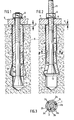
- the expansion anchor according to FIG. 1 consists of an expansion sleeve, generally designated 1, with a shell-shaped expansion element 2, and an anchor bolt, which is generally designated 3, penetrating the expansion sleeve 1.
- the expansion anchor is inserted into a hole, generally designated 4, with a conical extension 5 provided near the deepest in an item 6 to be fastened.
- the task of the expansion dowel is to clamp a flat object 7 to the fastening material 6, for which purpose a nut 9 supported by a washer 8 is used, which is screwed onto a load engaging means 11 designed as an external thread in the rear end region of the anchor bolt 3.
- the anchor bolt 3 has an expansion cone 12.
- the expansion sleeve 1 This is retractable into the expansion sleeve 1, the front part of which is provided with longitudinal slots 13 distributed over the circumference in order to facilitate radial expansion.
- the longitudinal slots 13 extend up to a recess 14, which makes it easier to bend open the longitudinally slotted part.
- the expansion sleeve 1 is provided with a circumferential recess 15, the depth of which decreases uniformly towards the front.
- the expansion dowel is inserted so deeply into the bore that the expansion sleeve 1 comes to lie with the rear end face by the dimension A corresponding to a few millimeters below the surface of the fastening material 6.
- the nut 9 is further screwed onto the anchor bolt 3, whereby it is moved outwards with the support of the nut 9 via the washer 8 and the object 7 on the workpiece 6 in the bore 4.
- the anchor bolt 3 takes the expansion sleeve 1 along in the direction of displacement via the expansion cone 12 without widening its longitudinally slotted part.
- the conical contour of the recess 15 causes a radial expansion of the expansion element 2 and thus its bracing towards the wall of the bore 4. This tensioning occurs after covering a slight axial displacement of the expansion sleeve 1, whereupon the latter is axially fixed at a remaining distance a from the surface of the fastening material 6.
- FIG 3 shows the expansion element 2 in the expanded state, wherein it is divided into four segments 2b by breaking connecting webs 2a distributed over the circumference.
Landscapes
- Engineering & Computer Science (AREA)
- General Engineering & Computer Science (AREA)
- Mechanical Engineering (AREA)
- Dowels (AREA)
Priority Applications (1)
| Application Number | Priority Date | Filing Date | Title |
|---|---|---|---|
| AT84103433T ATE27045T1 (de) | 1983-08-17 | 1984-03-28 | Spreizanker. |
Applications Claiming Priority (2)
| Application Number | Priority Date | Filing Date | Title |
|---|---|---|---|
| DE19833329732 DE3329732A1 (de) | 1983-08-17 | 1983-08-17 | Spreizanker |
| DE3329732 | 1983-08-17 |
Publications (2)
| Publication Number | Publication Date |
|---|---|
| EP0134391A1 true EP0134391A1 (fr) | 1985-03-20 |
| EP0134391B1 EP0134391B1 (fr) | 1987-05-06 |
Family
ID=6206786
Family Applications (1)
| Application Number | Title | Priority Date | Filing Date |
|---|---|---|---|
| EP84103433A Expired EP0134391B1 (fr) | 1983-08-17 | 1984-03-28 | Cheville d'écartement |
Country Status (6)
| Country | Link |
|---|---|
| US (1) | US4678383A (fr) |
| EP (1) | EP0134391B1 (fr) |
| JP (1) | JPS6057008A (fr) |
| AT (1) | ATE27045T1 (fr) |
| CA (1) | CA1250160A (fr) |
| DE (1) | DE3329732A1 (fr) |
Cited By (2)
| Publication number | Priority date | Publication date | Assignee | Title |
|---|---|---|---|---|
| EP0365475A3 (fr) * | 1988-10-15 | 1990-09-19 | HILTI Aktiengesellschaft | Cheville expansible |
| EP3536984A1 (fr) | 2018-03-05 | 2019-09-11 | HILTI Aktiengesellschaft | Ancre d'expansion pourvu de corps d'expansion supplémentaire |
Families Citing this family (27)
| Publication number | Priority date | Publication date | Assignee | Title |
|---|---|---|---|---|
| DE3525245A1 (de) * | 1985-07-15 | 1987-01-15 | Hilti Ag | Spreizanker |
| ES8609561A1 (es) * | 1985-10-31 | 1986-09-01 | Sanchez Velasco Vicente | Mejoras introducidas en los sistemas de anclaje mediante pernos roscados |
| DE3603801A1 (de) * | 1986-02-07 | 1987-08-20 | Bbc Reaktor Gmbh | Spannelement zum festlegen in einer bohrung eines bauteiles |
| DE3607607A1 (de) * | 1986-03-07 | 1987-09-17 | Braas & Co Gmbh | Befestigung von dichtungsbahnen und/oder daemmplatten am flachdach und dafuer bestimmte befestigungseinrichtung |
| US4869632A (en) * | 1988-03-02 | 1989-09-26 | United Technologies Corporation | Bolted connection for a turbine disk |
| US4917552A (en) * | 1989-09-05 | 1990-04-17 | Diversified Fastening Systems, Inc. | Pin drive anchor with locking sleeve |
| DE4133626A1 (de) * | 1991-10-10 | 1993-04-15 | Fischer Artur Werke Gmbh | Spreizduebel aus kunststoff |
| KR970003388Y1 (ko) * | 1993-06-29 | 1997-04-16 | 윤석규 | 문틀 |
| DE19513202A1 (de) * | 1995-04-11 | 1996-10-17 | Hilti Ag | Vorrichtung zur Verankerung von Bewehrungs- bzw. Spannstählen in Verankerungsgründen |
| DE19848704A1 (de) * | 1998-10-22 | 2000-04-27 | Hilti Ag | Hinterschnittdübel |
| DE19955684A1 (de) * | 1999-11-19 | 2001-05-23 | Hilti Ag | Ankerstange für Verankerungen mit organischen und/oder anorganischen Mörtelmassen |
| US6213697B1 (en) | 2000-02-25 | 2001-04-10 | Illinois Tool Works Inc. | Self-cutting expansion anchor |
| GB2383392B (en) * | 2001-12-18 | 2004-09-15 | Titus Int Plc | Improvements in fastening devices |
| GB0306060D0 (en) * | 2003-03-17 | 2003-04-23 | Ricardo Consulting Eng | A fastening device |
| US7357613B2 (en) * | 2006-01-26 | 2008-04-15 | Simpson Strong -Tie Company, Inc. | Expansion anchor with crack-arresting groove |
| DE102007049744A1 (de) * | 2007-10-16 | 2009-04-23 | Fischerwerke Gmbh & Co. Kg | Spreizanker |
| EP2573334B1 (fr) * | 2011-09-21 | 2015-11-11 | Pratt & Whitney Canada Corp. | Embout pour arbre de moteur à turbine à gaz, moteur à turbine à gaz et méthode correspondante pour obturer un arbre de moteur à turbine à gaz. |
| KR101599603B1 (ko) | 2013-08-26 | 2016-03-03 | 경북대학교 산학협력단 | 의료용 삽입 장치 |
| KR101639887B1 (ko) | 2014-11-11 | 2016-07-14 | 경북대학교 산학협력단 | 경추 고정 시스템 및 경추 고정용 기구에 사용되는 드라이버 |
| KR101608949B1 (ko) | 2014-11-19 | 2016-04-04 | 경북대학교 산학협력단 | 경추 고정 시스템, 경추 고정용 기구 및 경추 고정용 기구에 사용되는 드라이버 |
| KR101670768B1 (ko) | 2015-07-16 | 2016-10-31 | 경북대학교 산학협력단 | 나사못 앵커 조립체 |
| US10874445B2 (en) | 2015-10-13 | 2020-12-29 | Kyungpook National University Industry-Academic Cooperation Foundation | Screw fixing apparatus |
| KR101712610B1 (ko) | 2015-12-29 | 2017-03-06 | 경북대학교 산학협력단 | 로드 커넥터 |
| CN206171791U (zh) * | 2016-04-27 | 2017-05-17 | 零度智控(北京)智能科技有限公司 | 无人机 |
| KR101791004B1 (ko) | 2016-06-08 | 2017-10-27 | 경북대학교 산학협력단 | 나사못 앵커 조립체 및 나사못 앵커 조립체를 척추 나사못 고정술에 사용하는 방법 |
| CN112010115B (zh) * | 2020-09-17 | 2025-04-01 | 山东中恒景新碳纤维科技发展有限公司 | 一种用于料卷固定的机械式胀轴 |
| KR102378511B1 (ko) * | 2021-06-17 | 2022-03-23 | 문철식 | 전개형 슬리브, 앵커 볼트, 및 세트 앵커 |
Citations (5)
| Publication number | Priority date | Publication date | Assignee | Title |
|---|---|---|---|---|
| DE2429862A1 (de) * | 1974-06-21 | 1976-01-02 | Ahrends Befestigungstechnik Gm | Spreizduebel |
| GB1434048A (en) * | 1972-08-02 | 1976-04-28 | Upat Max Langensiepen Kg | Expanding anchor members |
| FR2349759A1 (fr) * | 1976-05-14 | 1977-11-25 | Itt | Ancre a dilatation |
| FR2360007A1 (fr) * | 1976-07-29 | 1978-02-24 | Maechtle Fritz | Boulon expansible pour scellements |
| DE3044051A1 (de) * | 1980-11-22 | 1982-06-16 | Anton 8500 Nürnberg Gerhard | Spreizduebel |
Family Cites Families (16)
| Publication number | Priority date | Publication date | Assignee | Title |
|---|---|---|---|---|
| US1650956A (en) * | 1922-04-14 | 1927-11-29 | Edward Ogden J | Bolt anchor |
| US3107569A (en) * | 1959-07-06 | 1963-10-22 | Lerick Lester | Expansion bolt with nut actuated expansion wedges |
| US3427919A (en) * | 1966-06-07 | 1969-02-18 | Wej It Expansion Products Inc | Wedge expansion device |
| DE2348873A1 (de) * | 1973-09-28 | 1975-04-10 | Heinrich B Schaefers | Konisch und parallel spannende duebel |
| US4052925A (en) * | 1975-11-05 | 1977-10-11 | U.S. Expansion Bolt Company | Expansion stud |
| DE2613499A1 (de) * | 1976-03-30 | 1977-10-13 | Heinrich B Schaefers | Bauwerksanker und verfahren zu seinem verankern |
| EP0002654B1 (fr) * | 1977-12-24 | 1982-01-20 | Heinrich Liebig | Dispositif de fixation avec une cheville verrouillée par clavetage dans une partie d'un trou présentant un plus grand diamètre |
| DE2828983A1 (de) * | 1978-07-01 | 1980-01-03 | Upat Max Langensiepen Kg | Verfahren zum festlegen eines bolzenankers o.dgl. sowie bolzenanker zum durchfuehren des verfahrens |
| DE3001902A1 (de) * | 1980-01-19 | 1981-07-23 | Artur Dr.H.C. 7244 Waldachtal Fischer | Befestigungselement aus metall fuer die verankerung in einem eine hinterschneidung aufweisenden bohrloch |
| DE3007650C2 (de) * | 1980-02-29 | 1982-04-01 | Artur Dr.H.C. 7244 Waldachtal Fischer | Spreizdübel für die Verankerung in konisch nach innen erweitert hergestellten Bohrlöchern |
| US4339217A (en) * | 1980-07-07 | 1982-07-13 | Drillco Devices Limited | Expanding anchor bolt assembly |
| DE3025816A1 (de) * | 1980-07-08 | 1982-02-04 | Werkzeugfabrik Fritz Mächtle GmbH & Co KG, 7015 Korntal | Verfahren zum befestigen von lasten mittels spreizanker sowie spreizanker zur durchfuehrung dieses verfahrens |
| DE3110485A1 (de) * | 1981-03-18 | 1982-09-30 | Phillips Drill Co GmbH, 6971 Hütschenhausen | Spreizanker |
| DE3121198A1 (de) * | 1981-05-27 | 1982-12-23 | Hilti AG, 9494 Schaan | Spreizduebel |
| DE3206290A1 (de) * | 1982-02-22 | 1983-09-01 | Hilti AG, 9494 Schaan | Spreizanker |
| NO159678C (no) * | 1982-05-14 | 1989-01-25 | Weidmann H Ag | Fjellsikringsanker. |
-
1983
- 1983-08-17 DE DE19833329732 patent/DE3329732A1/de active Granted
-
1984
- 1984-03-28 AT AT84103433T patent/ATE27045T1/de not_active IP Right Cessation
- 1984-03-28 EP EP84103433A patent/EP0134391B1/fr not_active Expired
- 1984-07-12 CA CA000458728A patent/CA1250160A/fr not_active Expired
- 1984-08-15 JP JP59169463A patent/JPS6057008A/ja active Pending
-
1986
- 1986-06-30 US US06/880,652 patent/US4678383A/en not_active Expired - Fee Related
Patent Citations (5)
| Publication number | Priority date | Publication date | Assignee | Title |
|---|---|---|---|---|
| GB1434048A (en) * | 1972-08-02 | 1976-04-28 | Upat Max Langensiepen Kg | Expanding anchor members |
| DE2429862A1 (de) * | 1974-06-21 | 1976-01-02 | Ahrends Befestigungstechnik Gm | Spreizduebel |
| FR2349759A1 (fr) * | 1976-05-14 | 1977-11-25 | Itt | Ancre a dilatation |
| FR2360007A1 (fr) * | 1976-07-29 | 1978-02-24 | Maechtle Fritz | Boulon expansible pour scellements |
| DE3044051A1 (de) * | 1980-11-22 | 1982-06-16 | Anton 8500 Nürnberg Gerhard | Spreizduebel |
Cited By (4)
| Publication number | Priority date | Publication date | Assignee | Title |
|---|---|---|---|---|
| EP0365475A3 (fr) * | 1988-10-15 | 1990-09-19 | HILTI Aktiengesellschaft | Cheville expansible |
| EP3536984A1 (fr) | 2018-03-05 | 2019-09-11 | HILTI Aktiengesellschaft | Ancre d'expansion pourvu de corps d'expansion supplémentaire |
| WO2019170405A1 (fr) | 2018-03-05 | 2019-09-12 | Hilti Aktiengesellschaft | Élément d'ancrage extensible avec corps d'expansion supplémentaire |
| US11852176B2 (en) | 2018-03-05 | 2023-12-26 | Hilti Aktiengesellschaft | Expansion anchor with additional expansion element |
Also Published As
| Publication number | Publication date |
|---|---|
| EP0134391B1 (fr) | 1987-05-06 |
| US4678383A (en) | 1987-07-07 |
| JPS6057008A (ja) | 1985-04-02 |
| DE3329732C2 (fr) | 1992-05-21 |
| DE3329732A1 (de) | 1985-03-07 |
| ATE27045T1 (de) | 1987-05-15 |
| CA1250160A (fr) | 1989-02-21 |
Similar Documents
| Publication | Publication Date | Title |
|---|---|---|
| EP0134391B1 (fr) | Cheville d'écartement | |
| EP0318426B1 (fr) | Piston à expansion avec coquille d'expansion et cône d'expansion rétractable | |
| EP0905385B1 (fr) | Cheville d'expansion | |
| DE2733007C2 (de) | Klebeanker | |
| DE3335628C2 (fr) | ||
| EP0192913B1 (fr) | Cheville expansible à indication de serrage | |
| DE3346537C2 (fr) | ||
| EP0365477B1 (fr) | Cheville expansible | |
| EP0188172A1 (fr) | Cheville à expansion | |
| EP0773373A1 (fr) | Cheville à douille métallique expansible | |
| WO1982004461A1 (fr) | Boulon d'ancrage | |
| DE1115081B (de) | Befestigungsvorrichtung | |
| EP0524137B1 (fr) | Cheville expansible | |
| DE2112591A1 (de) | Aufweitbare Befestigungsvorrichtung | |
| EP0306681A1 (fr) | Procédé d'ancrage d'une cheville d'expansion | |
| DE3115040C2 (fr) | ||
| EP0733813A1 (fr) | Cheville à expansion | |
| EP0905386B1 (fr) | Cheville d'expansion | |
| EP0209485B1 (fr) | Cheville à expansion | |
| DE2848478A1 (de) | Spreizduebel | |
| CH591637A5 (en) | Expansion bolt for concrete blind bore - has tapering portion with rounded convex surface exercising bush expansion pressure | |
| DE2435152A1 (de) | Spreizduebel | |
| DE3139174C2 (de) | Ankerbolzen | |
| CH398937A (de) | Expansionsdübel | |
| EP0171354B1 (fr) | Cheville à écartement |
Legal Events
| Date | Code | Title | Description |
|---|---|---|---|
| PUAI | Public reference made under article 153(3) epc to a published international application that has entered the european phase |
Free format text: ORIGINAL CODE: 0009012 |
|
| AK | Designated contracting states |
Designated state(s): AT BE CH FR GB LI NL SE |
|
| 17P | Request for examination filed |
Effective date: 19850401 |
|
| 17Q | First examination report despatched |
Effective date: 19860618 |
|
| GRAA | (expected) grant |
Free format text: ORIGINAL CODE: 0009210 |
|
| AK | Designated contracting states |
Kind code of ref document: B1 Designated state(s): AT BE CH FR GB LI NL SE |
|
| REF | Corresponds to: |
Ref document number: 27045 Country of ref document: AT Date of ref document: 19870515 Kind code of ref document: T |
|
| ET | Fr: translation filed | ||
| PLBE | No opposition filed within time limit |
Free format text: ORIGINAL CODE: 0009261 |
|
| STAA | Information on the status of an ep patent application or granted ep patent |
Free format text: STATUS: NO OPPOSITION FILED WITHIN TIME LIMIT |
|
| 26N | No opposition filed | ||
| PGFP | Annual fee paid to national office [announced via postgrant information from national office to epo] |
Ref country code: BE Payment date: 19920303 Year of fee payment: 9 |
|
| PG25 | Lapsed in a contracting state [announced via postgrant information from national office to epo] |
Ref country code: BE Effective date: 19930331 |
|
| BERE | Be: lapsed |
Owner name: HILTI A.G. Effective date: 19930331 |
|
| EAL | Se: european patent in force in sweden |
Ref document number: 84103433.3 |
|
| PGFP | Annual fee paid to national office [announced via postgrant information from national office to epo] |
Ref country code: SE Payment date: 19951219 Year of fee payment: 13 |
|
| PGFP | Annual fee paid to national office [announced via postgrant information from national office to epo] |
Ref country code: AT Payment date: 19960115 Year of fee payment: 13 |
|
| PGFP | Annual fee paid to national office [announced via postgrant information from national office to epo] |
Ref country code: FR Payment date: 19960130 Year of fee payment: 13 |
|
| PGFP | Annual fee paid to national office [announced via postgrant information from national office to epo] |
Ref country code: CH Payment date: 19960209 Year of fee payment: 13 |
|
| PGFP | Annual fee paid to national office [announced via postgrant information from national office to epo] |
Ref country code: GB Payment date: 19960318 Year of fee payment: 13 |
|
| PGFP | Annual fee paid to national office [announced via postgrant information from national office to epo] |
Ref country code: NL Payment date: 19960331 Year of fee payment: 13 |
|
| PG25 | Lapsed in a contracting state [announced via postgrant information from national office to epo] |
Ref country code: GB Effective date: 19970328 Ref country code: AT Effective date: 19970328 |
|
| PG25 | Lapsed in a contracting state [announced via postgrant information from national office to epo] |
Ref country code: SE Effective date: 19970329 |
|
| PG25 | Lapsed in a contracting state [announced via postgrant information from national office to epo] |
Ref country code: LI Effective date: 19970331 Ref country code: CH Effective date: 19970331 |
|
| PG25 | Lapsed in a contracting state [announced via postgrant information from national office to epo] |
Ref country code: NL Effective date: 19971001 |
|
| REG | Reference to a national code |
Ref country code: CH Ref legal event code: PL |
|
| GBPC | Gb: european patent ceased through non-payment of renewal fee |
Effective date: 19970328 |
|
| PG25 | Lapsed in a contracting state [announced via postgrant information from national office to epo] |
Ref country code: FR Free format text: LAPSE BECAUSE OF NON-PAYMENT OF DUE FEES Effective date: 19971128 |
|
| NLV4 | Nl: lapsed or anulled due to non-payment of the annual fee |
Effective date: 19971001 |
|
| EUG | Se: european patent has lapsed |
Ref document number: 84103433.3 |
|
| REG | Reference to a national code |
Ref country code: FR Ref legal event code: ST |