EP0134423A2 - Einlesbares Zeichengeneratorgerät und Verfahren zum Einlesen desselben - Google Patents
Einlesbares Zeichengeneratorgerät und Verfahren zum Einlesen desselben Download PDFInfo
- Publication number
- EP0134423A2 EP0134423A2 EP84106488A EP84106488A EP0134423A2 EP 0134423 A2 EP0134423 A2 EP 0134423A2 EP 84106488 A EP84106488 A EP 84106488A EP 84106488 A EP84106488 A EP 84106488A EP 0134423 A2 EP0134423 A2 EP 0134423A2
- Authority
- EP
- European Patent Office
- Prior art keywords
- character
- buffer
- codes
- code
- addressable
- Prior art date
- Legal status (The legal status is an assumption and is not a legal conclusion. Google has not performed a legal analysis and makes no representation as to the accuracy of the status listed.)
- Withdrawn
Links
Images




Classifications
-
- G—PHYSICS
- G09—EDUCATION; CRYPTOGRAPHY; DISPLAY; ADVERTISING; SEALS
- G09G—ARRANGEMENTS OR CIRCUITS FOR CONTROL OF INDICATING DEVICES USING STATIC MEANS TO PRESENT VARIABLE INFORMATION
- G09G5/00—Control arrangements or circuits for visual indicators common to cathode-ray tube indicators and other visual indicators
- G09G5/22—Control arrangements or circuits for visual indicators common to cathode-ray tube indicators and other visual indicators characterised by the display of characters or indicia using display control signals derived from coded signals representing the characters or indicia, e.g. with a character-code memory
- G09G5/222—Control of the character-code memory
- G09G5/225—Control of the character-code memory comprising a loadable character generator
-
- G—PHYSICS
- G06—COMPUTING OR CALCULATING; COUNTING
- G06F—ELECTRIC DIGITAL DATA PROCESSING
- G06F3/00—Input arrangements for transferring data to be processed into a form capable of being handled by the computer; Output arrangements for transferring data from processing unit to output unit, e.g. interface arrangements
- G06F3/14—Digital output to display device ; Cooperation and interconnection of the display device with other functional units
- G06F3/153—Digital output to display device ; Cooperation and interconnection of the display device with other functional units using cathode-ray tubes
Definitions
- This invention relates to a loadable character generator apparatus and related loading method that is to an apparatus and method for generating various type of character sets including multiple national language character sets, suitable in computer systems.
- the character generator is the means for translating from the character code associated with a particular character to be displayed on a cathode ray tube to the dot pattern for that particular character.
- character generators are usually implemented in hardware using a table look-up scheme with a table stored in a dedicated memory, usually a ROM/PROM with the character code serving as a portion of the address to the memory.
- ROM/PROM read-only memory
- Each type of raster scan pattern has its advantages and disadvantages.
- An advantage of the minature raster scan over the TV raster scan is that the character code may be presented at a slower rate for the same number of characters per row and rows per screen.
- the two main advantages in using a TV scan are the cost saving in the display portion of the system (the CRT and deflection circuits), and the ability to superimpose characters on pictures or other video (such as maps, etc.). These advantages generally come into play, however, only if one can operate at speeds at least equal to 'commercial' or 'entertainment' TV rates. Then one can buy a mass produced off the shelf display system relatively inexpensively, or simply transmit messages to TV sets that are already being used for other purposes, also mix character signals with other video signals operating at commercial TV rates.
- At least the first advantage is lost, however, if the cost of producing character video signals at commercial TV rates exceed the cost saving in the display portion.
- the information controlling on/off condition of the beam must be synchronized with the beam scan. This is true whether the beam follows TV scan pattern or a minature scan pattern. If, however, the TV scan pattern is to operate at commercial TV rates, or faster, the requirement of synchronization means that the electronic components must work at rates which were prohibited in the 1950's and too expensive to be commercial through the early 1960's.
- the coded form of input data must be translated to video data to control the on/off condition of the beam of the CRT as it sweeps in a miniraster or TV raster scan.
- the patent literature from the 1950's discloses translators in the form of digital circuits, for translating from a 6-bitcharacter code to a pulse train which will display a 5 by 7 character matrix on a CRT.
- the monoscope character generator generally does not produce a train of 35 equal-length pulse positions, each of which can be on or off, therefore, it is not generally associated with a character matrix type of display. Rather it receives the 6-bit character code and produces a pulse train in which the pulse length correspond to the precise width of the character to be displayed, at various locations along the character height.
- a monoscope is the small CRT, generally cylinderical in shape, which has a target imprinted or stenciled with characters, instead of a screen.
- the beam is deflected to a particular character on the target, in response to the 6-bit character code received, and it then scans the character.
- the monoscope produces an output signal which is the pulse train having pulse lengths or duration corresponding to the time the beam is crossing the character.
- This pulse train closely replicates the character shape, and, consequently produces much better quality characters than the pin hole from a 5 by 7 character matrix.
- All of the character display CRT systems of interest here use signal storage, so that the CRT screen can be repeatedly 'refreshed'.
- a full screen of character-representing signals (sometimes called a 'page') is stored and used repeatedly to 'refresh' the screen.
- the storage is eitherof two types.
- the first type involves storing the 6-bit character codes that are received. The codes can then be read out from storage, and translated to the video signal, as the CRT beam is scanning.
- the second type of storage involves translating the 6-bit character codes, as they are received, to their corresponding video signals and then storing the video bits. The video bits can then be read out from storage to the CRT as the CRT beam is scanning While both of these storage approaches involve the storage of codes, and both codes are generally binary in nature and represent characters, they can be conveniently referred to as 'character code storage' and 'video bit storage' respectively.
- Video bit storage takes more storage space, since it must store a screen or page of 35-bit character matrix codes while the character code storage needs only a screen or page of 6-bit character codes
- the advantage of video bit storage is that the character codes are only translated once, and the video bits are then stored and read out concurrently with a beam scan so that the character codes need not to be translated concurrently with each scan of a scan line and, therefore, the translation need not keep pace with the high-speed beam scan.
- video-bit storage is particularly suited to the variable placement of the characters on the screen.”
- a particular character i.e. blinking, underlining, etc.
- the soft loadable character generator of the invention replaces the ROM/PROM by a RAM utilizing 2K by 8 RA M memories, a 4K by 8 memory, 4 MUX chips, and a Motorola 6845 CRT Controller with various registers.
- the character code is used as a portion of the address which is used to address the RAM which serves as the character generator.
- the remainder of the address for the character generator is taken from the scan line number.
- the address is comprised of 12 bits with the 8 high order bits comprising the character code and the 4 low order bits comprising the scao line number.
- the picture is formed by an electron beam which illuminates various points on the phosphor coating of the screen as it scans the area in which the image is to be displayed. Normally, the beam scans across one horizontal line at a time, starting at the top of the screen and moving sequentially down the screen to the bottom. This pattern of scan in which the beam proceeds across the entire width of the CRT screen before scanning a second horizontal line is referred to as the television raster scan pattern.
- the beam can be used to form a recognizable message or image. Because of its speed, the beam's movement is not detectable by the eye.
- Each character of the set can be represented by an array of dots in a rectangular matrix having fixed dimensions (e.g., 5 dots wide and 7 dots high, or as in the instant invention, 7 dots wide and 9 dots high).
- the character is displayed on the CRT screen within a character space which includes the dot matrix of the character, and additional blank spaces to separate the characters on the screen (e.g. 9 dots wide by 12 scan lines high). Two such adjacent character spaces are shown in prior art Figure lA.
- the computer codes for each of the characters to be written in a row across the screen are sequentially provided from,a memory to a decoder or "character generator".
- timing and control circuitry produce count signals which represent the scan line of the raster and the dot position along the scan line.
- Character-code information, the scan-line count signal, and the dot position count signal are applied to the character generator, label Digital to Video Generator 20l, which converts the signals into a 2-level, serial digital output.
- the output signal is applied to the television monitor circuitry 202 as a video signal.
- One digital level of the signal corresponds to a dot and turns on the electron beam to write a dot on the television screen.
- the other digital level corresponds to the absence of a dot, and leaves the electron beam turned off so that no dot is written.
- the electron beam After completing one scan line, the electron beam flies back to the starting side of the screen, (but down one position due to the vertical sweep) to start the next scan line.
- the sequential application of character codes, scan line count and dot position count is then repeated, this time generating the video signals for the next dot slice of each of the characters in the row.
- the additional rows of characters making up the message to be displayed on the screen are written.
- the procedure is repeated at a rate of 50 or 60 times per second (depending on country) so as to "refresh" the screen and create a ⁇ display which the human eye perceives as the persistent, non-flinckering image.
- FIG. 1B there is an example of the translation of the code for the character "1" which is to be displayed on the screen.
- the binary codes that are used for identifying the various characters were supplied directly to the CRT, the pattern on the screen would not generally be recognizable.
- the 6-bit code 000111 might represent a number "7”, but would appear as 3 dark spots followed by 3 bright spots, or vice versa. Consequently it is necessary to translate the 6-bit binary code into a video signal which will represent a normal appearing character.
- FIG. 1B shows the code to pattern translation for the number "1"
- the video code for the first scan line is 00100 and the video signal which represents this code is a pulse in the position where the dot is to appear.
- the video code is 01100 whereby a video signal representing this video code is two pulses causing two dots to appear on scan line two. (When the final scan line is completed, the number "1" appears on the screen).
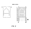
- Figure 3 there is shown one character on one row in one column. There are 80 such character columns across the screen, and there are 25 character rows; thus 2000 characters can be generated on the page or screen.
- Figure 3 shows how the letter "A" would be formed within the boundaries 301 to 302 when the total of 12 raster rows comprising one character row have been completed. (It should be noted that 9 raster lines are utilized in character generation; whereas 3 are added as a space between character lines.)
- this character (which may be part of a message), it first must be stored in a memory or buffer 7 shown on Figure 4. In order to write this character on the screen, it must be generated by the character generator 14.
- the character generator stores different standard characters at different addresses which can be used to generate the characters of any message on the screen which is stored in buffer 7 as previously described.
- the pattern stored in the character generator 14 is addressed by utilizing the code of the character in the message as part of the address. In this case the hexadecimal code for "A" is 041, while the decimal code is 65.
- the address of the letter "A" therefore, would be 65x16 for the first raster line, and for the second it would be (65x16)+1, etc.
- the patterns for different characters of the message are similarly addressed by their codes and a portion of each is generated until one full character row is generated by 9 successive raster lines.
- FIG. 4 there is shown a high level logic block diagram of the invention.
- Two busses a 16-bit address bus 1 and an 8-bit data bus 2 are coupled to commercially available Motorola 6809 microprocessor 20.
- a Central processing unit (not shown) communicates to the terminal, of which the invention is a portion, via the address and data busses 1, 2.
- Two commercially available 6116 RAMs 7 and 8 respectively are coupled to the 8-bit data bus 2 via commercially available 74LS245 transceivers 9 and 10.
- the transceivers 9 and 10 can transmit data in either direction from the bus to the RAM or from the RAM to the bus.
- the data is placed into the RAM 7 or 8 at addresses controlled by the microprocessor 20 via address bus 1.
- Selection of the RAM 7 or 8 in which data or attributes is to be stored is done via the low order bit of address bus 1 through logic not shown. Accordingly, when a message is to be written on the CRT screen (not shown), data (i.e. the message) is written into the RAM 7 via transceiver 9 at addresses provided by the microprocessor 20. In a similar manner, attributes (i.e. underlining, blinking, etc.) are written via data transceiver 10 into RAM 8. In order to write on the CRT screen (not shown), it must be done piecemeal for each character as each scan line progresses across the screen (not shown), as previously described supra. Subsequently, under control of the CRT 3, each character of the message is addressed and read out into register 11.
- each attribute corresponding to any given character is simultaneously read out into register 12.
- a full address comprised of 8 high-order bits (which in reality represent the character code) and 4 low-order bits (which represent the scan lines, and which count 12 different scan lines 0-11) is presented to character generator 14.
- Character generator 14 is comprised of two commercially available 6116 RAMs which stores a set of character patterns of any distinctive type which can be addressed by the address formed by concatenating the character code with a scan line code as described above.
- each separate scan line of a CRT screen progresses through 80 character time-frames a portion of each character is written in each time-frame on each scan line as indicated at each time frame by the character temporarily stored in register 11 for that particular time-frame.
- the scan line address will cycle from 0 to 11, and when 12 complete scan lines have been made on the screen, then 80 characters would be completed on the screen as one row.
- the shift register 15 coupled to the character generator 14 are the means for converting parallel data to serial data.
- One feature of the invention is to have the attribute for a particular character arrives at the screen (not shown) at precisely the same time that the character arrives. This is accomplished by storing the character data in the screen data buffer and the attribute data in the screen attribute buffer. As each address is presented to the screen data buffer and the screen attribute buffer, the character being addressed is placed in register 11 and the attribute being addressed is placed in register 12. Thus the character code and the attribute code are available to the control logic to be written on the screen at the same time. Thus, since both the character information and attribute information is available at precisely the same time, it makes for very precise timing and a clear image on the screen.
- the invention provides a means of loading the character generator RAM 14 of Figure 4 which requires the minimum of additional hardware over that required for the character generation function.
- the heart of the invention consists of adding the single register 13 of Figure 4 to provide a path for the data to be written into the character generator 14, together with a Character-Generator-Load mode flip-flop 17 and associated control element 18 of Figure 7.
- the Character Generator RAM is set to Write mode and the tristate output of register 13 described above is enabled so that the contents of the register 13 are written into RAM 14 on every character clock cycle so long as this mode remains in effect.
- the address at which the data are written is the twelve-lead address consisting of the 4 scan line leads emanating from the CRTC 3 and the 8 leads emanating from the register 11 just as when the RAM 14 is used for its normal character generation function. Also note that register 11 is fed by the screen "data" buffer RAM 7 while the register 13 which contains the data to be written is fed by the screen "attribute” buffer RAM 8.
- the mentioned architecture leads to a loading method by which the character generator 14 is loaded by using as data to be registered the content of the screen attribute buffer 8, and as a portion of the address where to write, the content of the screen data buffer 7. Therefore loading of character generator 14 may be performed with the same program routine which is used to read the character generator 14 for display purpose, the only difference being that the controlled operation are write ones not read ones and that certain program parameters are different.
- loading of screen data buffer 7 and screen attribute buffer 8 with information required to load the character generator 14, may be performed with the same programs which are normally used to load the two buffers for the purpose of providing the information display on the screen, under control of the same microprocessing unit 20.
- a combination of a "load” of the screen data and attribute RAMs and a programming of the CRTC 3 in conjunction with the Load-Mode hardware described above will cause the desired table to be loaded into the character generator 14.
- the "attribute" screen buffer is loaded with the screen patterns and the "data” screen buffer is loaded with the character codes normally used to evoke the associated patterns.
- the screen attribute and data buffers are respectively loaded with 128 patterns and the corresponding character codes, the codes being replicated 16 times over.
- the details of the ordering of these information within the screen buffer RAMs are governed by the operation of the CRTC 3.
- the CRTC 3 is capable of being loaded with certain parameters whhich will then control its operation, including the following:
- One purpose of the CRTC is to generate the proper sequence of addresses to address the screen buffer 7 and 8 and to allow for the display of the patterns associated with the codes stored in the buffer while also generating scan line numbers to serve as part of the character generator address as explained earlier.
- Another purpose of thr CRTC is to afford ease of scrolling by allowing the beginning of screen to correspond to an arbitrary location in the screen buffer, hence the Starting Address parameter.
- the operation of the CRTC consists of emitting a sequence of screen buffer addresses and scan line numbers (as well as synchronizing pulses not covered here).
- the initial sequence emitted consists of a linear sequence of screen buffer addresses commencing with the screen buffer Starting Address, the length of the sequence being equal to the "Number of Characters per Row” parameter, while holding the emitted scan line number at ZERO.
- this identical sequence of screen buffer addresses is repeated while holding the emitted scan line number at a value of ONE.
- This process is repeated for the number of times specified by the "Number of Scan Lines per Character Row" parameter.
- the entire process is then repeated with the next sequential set of screen buffer addresses, this level of iteration being repeated until the number of repetitions is equal to the "Number of Character Rows" parameter.
- the initial sequence would consist of the first 80 addresses (commencing with the Screen Buffer Starting Address) with the scan line number held equal to ZERO followed by a sequence consisting of these same first 80 addresses with the scan line number held equal to ONE, etc. until the scan line number equals 11.
- the second 80 addresses are generated 12 times over etc., until lastly the 25th set of 80 addresses are generated twelve times over (with the scan line number ranging from 0-11 with each repetition of the same set of addresses).
- Figure 8 shows the organization of data in the Screen Buffer RAMs 7 and 8.
- the left half of each column represents the contents of the "data" buffer 7, while the right half represents the contents of the "attribute” buffer 8.
- the numbers across the top are the decimal address of the first 128 locations (those in the first erow) while the numbers along the left side show the range of addresses encompassed in each of the rows.
- the case shown in Figure 8 is for the first phase; i.e., for character codes 0-127 and as can be seen, the contents of the "data" buffer (the left half of each column) is simply this range of numbers in sequence and replicated 16 times over.
- the program may be the same which is normally used to load the screen buffer with a message to be written on the CRT screen via transceiver 9 at addresses provided by the microprocessor 20 through multiplexor 6.
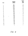
- Figure 9 shows the values of the screen buffer Starting Address and Number of Scan lines per character row parameters for each of the sixteen passes.
- the Starting Address is set to the address corresponding to the beginning of the last scan line of Figure 8, this being the area where the scan line 15 slices of the character patterns are stored.
- the CRTC will sequence through this row of addresses sixteen times overwhile stepping the scan line number from 0 to 15. Now, since the screen data buffer 7 contains the sequence 0-127 and since each of these numbers together with the scan line number, forms the address to the Character Generator RAM 14, the binary representation of scan line 15 patterns (the right halves of each column of the last row of Figure 8) will -be written sixteen times into the Character Generator 14. The first fifteen of these iterations are not desired, but this sixteenth does load the pattern information of scan line 15 into the proper locations.
- the Starting Address is set to 1792 (the next to last scan line of Figure 8) but this time the number Df scan lines is programmed for 15. This means that on this pass the scan line numbers generated by the CRTC will only range from 0 to 14 so that the pattern information of scan line 15 which was loaded in the first pass will remain intact. Again, on this pass, only the last of the iterations (fifteen this time) through the 128 specified addresses in the screen buffer is required. Thus the process proceeds, moving up one scan line of Figure 8 each time, while decreasing the Number of Scan Lines parameter by one until on the last (sixteenth) pass there is only one sequencing through the first 128 locations. At this point, the half of the character generator appropriate to the current phase is fully loaded.
- screen data buffer 7 and screen attribute buffer 8 coupled together comprise a 2Kx16 screen buffer.
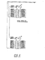
- Data from the 8-bit data bus 2, shown on Figure 4 is applied to data bus leads DBUSOO through DBUS07 of both transceivers 9 and 10.
- Screen buffer data signals SBDATO-SBDAT7 on transceiver 9 are applied to the SBDATO-SBDAT7 terminals of screen data buffer 7 when data is being transmitted from the bus to be written into the screen data buffer 7.
- data from screen data buffer 7 can be read out onto bus 2 via transceiver 9.
- data representing attributes can be written or read out of the screen attribute buffer 8, and to or from the bus 2 via the data bus terminals DBUSOO through DBUS07 and screen buffer attribute terminals SBATTO through SBATT7 of transceiver 10.
- Transceivers 9, 10 are controlled in flow direction by signals ENS B DT, ENSBAT, UBUSRD issued by microprocessor 20. In transferring information into or out of the screen buffer memories 7 and 8, it is transmitted to or from locations addressed by signals on terminals SBAD09 through SBAD19. Additionally, when writing buffer memories 7 and 8 the write enable signal WESBAT or WESBDT of screen buffer attribute 8 or screen data buffer 7 must be true. WESBAT or WESBDT are issued by MP 20. This technique of using unique write enable signals to select one or the other memory permits the screen data to be stored in one memory bank; whereas the screen attributes are stored in another memory bank.
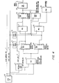
- raster scan line address signals on terminals RASTR1 through RASTR4 of CRT controller 3 are applied to the character generator 14 on raster scan address line terminals RASTR1 through RASTR4 of character generator 14. Accordingly as raster scan line 0-11 are addressed, and as each character is presented to the character generator in synchronism with the scan line time intervals, the character generator 14 decodes a portion of the character and provides video output signals to terminals VIDDOO through VIDD07 of shift registers 15 on sheet 3 of Figure 7 via lines VIDDOO - VIDD07 of sheet 2 of Figure 7. In sheet 2 of Figure 7 the shown rhombi indicates connection nodes.
- Signal REPEAT is of no interest for the purpose of the invention.
- the CRT Controller (CRTC)3 generates all of the timing for the display. This consists of the screen buffer address sequence emitted on terminals CRTA09-CRTA19, the raster scan line number sequence emitted on terminals RASTR1- R ASTR4, as well as the horizontal and vertical synchronizing signals HSYNC1 and VSYNC2 and the display enable signal DISPLY.
- the CRTC 3 is capable of being loaded with control parameters by virtue of having the signals UDATAO-UDATA7 from data bus 2 applied to its data terminals and suitable control signals being applied by microprocessor 20, such as UBUSRD, PHAS.E, ABUS18 and CRTCCS.
- microprocessor 20 such as UBUSRD, PHAS.E, ABUS18 and CRTCCS.
- the Motorola "Microprocessor data manual" 1982 provides at pages 4-479 a detailed description of the CRT controller and its operation.
- Signal ZGNDE 12, SYSCLR and CCLR01 are conventional ground, reset and timing signals received by the controller.
- CURSOR signal issued by the controller is used to validate cursor addresses and is of no interest here.
- the multiplexors (MUX) 6 are for the purpose of selecting an address for the screen buffer RAMs, from either the CRTC 3 or from the address bus 1.
- the former case is selected during a portion of every display character time (as controlled by clock CCLK01) to allow for reading out of the coded display data and attributes; while the latter case is selected under control of the microprocessor 20 for the purpose of causing the information to be displayed to be properly stored in the screen buffer.
- Flip-flop 17 of D type is set by command GENLD issued by microprocessor 20 on the occurrence of a particular clock signal CCLKLD (which could be CCLR01 as well, enabled by a suitable other signal) and when set produces signal CGENLD.
- CGENLD enables, through NAND 18 the writing into RA M 14.
- DSPENA and SBCGWP are further control signals which enable writing if further condition are met, for instance the CRT displat must be disabled from operation.
- CGENLD further enables, (through NOT 12) register 13 to output the stored information.
- DECGEN is a signal which must be at level 0 to enable the output of RAM 14 in read operations. Write operations are not affected by the level of such signal.
- register 13 as a load path for loading the character generator from the screen attribute RAM it would be possible to connect the outputs of register 12 to the input/output of the character generator through a set of control gates, the latching function of register 13 being in such a case performed by register 12.
- control flip-flop 17 which has been shown as an individual element, may be a cell of a status register, latching several status conditions of the loadable character generatus apparatus of the invention, and among them the condition "load mode".
- microprocessor such as the Motorola MC68000 having 16 bit data bus, instead of the 6809 microprocessor, shown in Figure 4, leads to the possibility of simultaneous parallel loading of screen data buffer 7 and screen attribute buffer 8 so that the two buffers may actually form a single screen buffer having a 16 bit parallelism which may provide at the same time both address and data to be loaded information to character generator 14.
Landscapes
- Engineering & Computer Science (AREA)
- Theoretical Computer Science (AREA)
- Physics & Mathematics (AREA)
- General Physics & Mathematics (AREA)
- Human Computer Interaction (AREA)
- General Engineering & Computer Science (AREA)
- Computer Hardware Design (AREA)
- Digital Computer Display Output (AREA)
- Controls And Circuits For Display Device (AREA)
Applications Claiming Priority (4)
| Application Number | Priority Date | Filing Date | Title |
|---|---|---|---|
| US50409383A | 1983-06-13 | 1983-06-13 | |
| US50409283A | 1983-06-13 | 1983-06-13 | |
| US504092 | 1983-06-13 | ||
| US504093 | 1983-06-13 |
Publications (2)
| Publication Number | Publication Date |
|---|---|
| EP0134423A2 true EP0134423A2 (de) | 1985-03-20 |
| EP0134423A3 EP0134423A3 (de) | 1988-10-05 |
Family
ID=27054721
Family Applications (1)
| Application Number | Title | Priority Date | Filing Date |
|---|---|---|---|
| EP84106488A Withdrawn EP0134423A3 (de) | 1983-06-13 | 1984-06-06 | Einlesbares Zeichengeneratorgerät und Verfahren zum Einlesen desselben |
Country Status (7)
| Country | Link |
|---|---|
| EP (1) | EP0134423A3 (de) |
| KR (1) | KR850000717A (de) |
| AU (1) | AU560444B2 (de) |
| DK (1) | DK287984A (de) |
| ES (1) | ES8601512A1 (de) |
| FI (1) | FI842153A7 (de) |
| YU (1) | YU103484A (de) |
Cited By (1)
| Publication number | Priority date | Publication date | Assignee | Title |
|---|---|---|---|---|
| FR2613109A1 (fr) * | 1987-03-27 | 1988-09-30 | Ibm | Systeme d'affichage a balayage de trame avec generateur de caracteres a memoire a acces aleatoire |
Family Cites Families (8)
| Publication number | Priority date | Publication date | Assignee | Title |
|---|---|---|---|---|
| US3729730A (en) * | 1971-04-14 | 1973-04-24 | Cogar Corp | Display system |
| GB1513179A (en) * | 1975-11-17 | 1978-06-07 | British Broadcasting Corp | Data display apparatus |
| FR2419623A1 (fr) * | 1978-03-10 | 1979-10-05 | Telediffusion Fse | Systeme de transmission numerique et d'affichage de textes et de graphismes sur un ecran de television |
| GB1586431A (en) * | 1978-04-11 | 1981-03-18 | Philips Electronic Associated | Data transmission |
| GB2059728B (en) * | 1979-09-27 | 1983-03-30 | Ibm | Digital data display system |
| DE3272407D1 (en) * | 1981-02-23 | 1986-09-11 | Texas Instruments Inc | Display system with multiple scrolling regions |
| US4439761A (en) * | 1981-05-19 | 1984-03-27 | Bell Telephone Laboratories, Incorporated | Terminal generation of dynamically redefinable character sets |
| AU555262B2 (en) * | 1982-08-06 | 1986-09-18 | International Control Automation Finance Sa | Cathode ray tube display |
-
1984
- 1984-05-30 FI FI842153A patent/FI842153A7/fi not_active Application Discontinuation
- 1984-06-05 AU AU29083/84A patent/AU560444B2/en not_active Ceased
- 1984-06-06 EP EP84106488A patent/EP0134423A3/de not_active Withdrawn
- 1984-06-12 ES ES533328A patent/ES8601512A1/es not_active Expired
- 1984-06-12 DK DK287984A patent/DK287984A/da not_active Application Discontinuation
- 1984-06-13 KR KR1019840003304A patent/KR850000717A/ko not_active Withdrawn
- 1984-06-13 YU YU01034/84A patent/YU103484A/xx unknown
Cited By (3)
| Publication number | Priority date | Publication date | Assignee | Title |
|---|---|---|---|---|
| FR2613109A1 (fr) * | 1987-03-27 | 1988-09-30 | Ibm | Systeme d'affichage a balayage de trame avec generateur de caracteres a memoire a acces aleatoire |
| EP0283579A3 (en) * | 1987-03-27 | 1989-06-07 | International Business Machines Corporation | Raster scan display system with random access memory character generator |
| BE1001069A3 (fr) * | 1987-03-27 | 1989-06-27 | Ibm | Systeme d'affichage a balayage de trame avec generateur de caracteres a memoire a acces aleatoire. |
Also Published As
| Publication number | Publication date |
|---|---|
| DK287984A (da) | 1984-12-14 |
| AU2908384A (en) | 1984-12-20 |
| ES533328A0 (es) | 1985-10-16 |
| KR850000717A (ko) | 1985-02-28 |
| DK287984D0 (da) | 1984-06-12 |
| ES8601512A1 (es) | 1985-10-16 |
| FI842153A7 (fi) | 1984-12-14 |
| YU103484A (en) | 1987-10-31 |
| FI842153A0 (fi) | 1984-05-30 |
| AU560444B2 (en) | 1987-04-09 |
| EP0134423A3 (de) | 1988-10-05 |
Similar Documents
| Publication | Publication Date | Title |
|---|---|---|
| US4258361A (en) | Display system having modified screen format or layout | |
| EP0012793A2 (de) | Verfahren zum Anzeigen von graphischen Bildern durch ein Gerät mit gerasterter Anzeige und eine Vorrichtung zur Ausführung des Verfahrens | |
| US4486856A (en) | Cache memory and control circuit | |
| US4203102A (en) | Character display system | |
| US3774161A (en) | Visual display system | |
| US3555520A (en) | Multiple channel display system | |
| US4205312A (en) | Method and apparatus for causing a dot matrix display to appear to travel | |
| US4684942A (en) | Video display controller | |
| US4309700A (en) | Cathode ray tube controller | |
| US3872446A (en) | Visual display system | |
| EP0215984A1 (de) | Graphik-Anzeigegerät mit kombiniertem Bitpuffer und Zeichengraphikspeicherung | |
| US4703322A (en) | Variable loadable character generator | |
| EP0085480A2 (de) | Video-Anzeigesysteme | |
| GB2151440A (en) | A circuit for increasing the number of pixels in a scan of a bit mapping type video display | |
| US4231032A (en) | Variable accuracy trend graph display apparatus | |
| EP0134423A2 (de) | Einlesbares Zeichengeneratorgerät und Verfahren zum Einlesen desselben | |
| US4616160A (en) | Multiple beam high definition page display | |
| CA1228942A (en) | Soft digital image apparatus | |
| KR900006942B1 (ko) | 데이타 디스플레이 시스템용 데이타 신호 제공 장치 | |
| US4633244A (en) | Multiple beam high definition page display | |
| US4633142A (en) | Multibeam graphic display system utilizing bit mapping memory | |
| GB2094116A (en) | Improvements in visual display devices | |
| CA1229440A (en) | Variable loadable character generator | |
| JPS5897378A (ja) | 走査形デイスプレイの表示制御方法および表示制御装置 | |
| US4603279A (en) | Cathode ray tube (CRT) having shaped beams |
Legal Events
| Date | Code | Title | Description |
|---|---|---|---|
| PUAI | Public reference made under article 153(3) epc to a published international application that has entered the european phase |
Free format text: ORIGINAL CODE: 0009012 |
|
| AK | Designated contracting states |
Designated state(s): BE CH DE FR GB IT LI NL SE |
|
| PUAL | Search report despatched |
Free format text: ORIGINAL CODE: 0009013 |
|
| AK | Designated contracting states |
Kind code of ref document: A3 Designated state(s): BE CH DE FR GB IT LI NL SE |
|
| 17P | Request for examination filed |
Effective date: 19890310 |
|
| RAP1 | Party data changed (applicant data changed or rights of an application transferred) |
Owner name: BULL HN INFORMATION SYSTEMS INC. |
|
| STAA | Information on the status of an ep patent application or granted ep patent |
Free format text: STATUS: THE APPLICATION HAS BEEN WITHDRAWN |
|
| 18W | Application withdrawn |
Withdrawal date: 19890715 |
|
| R18W | Application withdrawn (corrected) |
Effective date: 19890715 |
|
| RIN1 | Information on inventor provided before grant (corrected) |
Inventor name: MURRAY, THOMAS L, JR. Inventor name: SIWIK, JAMES C. Inventor name: GOSS, GARY J. Inventor name: HOLTEY, THOMAS O. |