EP0134428B1 - Lesevorrichtung zum optischen Abtasten von auf einem bewegten plattenförmigen Träger aufgezeichneten Informationen - Google Patents
Lesevorrichtung zum optischen Abtasten von auf einem bewegten plattenförmigen Träger aufgezeichneten Informationen Download PDFInfo
- Publication number
- EP0134428B1 EP0134428B1 EP84106715A EP84106715A EP0134428B1 EP 0134428 B1 EP0134428 B1 EP 0134428B1 EP 84106715 A EP84106715 A EP 84106715A EP 84106715 A EP84106715 A EP 84106715A EP 0134428 B1 EP0134428 B1 EP 0134428B1
- Authority
- EP
- European Patent Office
- Prior art keywords
- scanning head
- reading device
- transducer
- light
- scanning
- Prior art date
- Legal status (The legal status is an assumption and is not a legal conclusion. Google has not performed a legal analysis and makes no representation as to the accuracy of the status listed.)
- Expired
Links
- 230000003287 optical effect Effects 0.000 title claims description 9
- 230000009471 action Effects 0.000 claims description 4
- 230000010355 oscillation Effects 0.000 claims description 4
- 238000001514 detection method Methods 0.000 claims description 3
- 230000000694 effects Effects 0.000 claims description 3
- 238000012544 monitoring process Methods 0.000 claims 3
- 238000010276 construction Methods 0.000 claims 1
- 230000004907 flux Effects 0.000 claims 1
- 238000012937 correction Methods 0.000 description 5
- 238000005452 bending Methods 0.000 description 4
- 230000032683 aging Effects 0.000 description 3
- 230000004888 barrier function Effects 0.000 description 3
- 239000000969 carrier Substances 0.000 description 3
- 230000008859 change Effects 0.000 description 2
- 238000011161 development Methods 0.000 description 2
- 230000018109 developmental process Effects 0.000 description 2
- 238000012552 review Methods 0.000 description 2
- 239000004065 semiconductor Substances 0.000 description 2
- 230000005540 biological transmission Effects 0.000 description 1
- 238000011109 contamination Methods 0.000 description 1
- 230000005520 electrodynamics Effects 0.000 description 1
- 230000003993 interaction Effects 0.000 description 1
- 230000007246 mechanism Effects 0.000 description 1
- 238000000034 method Methods 0.000 description 1
- 230000004048 modification Effects 0.000 description 1
- 238000012986 modification Methods 0.000 description 1
- 238000012545 processing Methods 0.000 description 1
- 230000004044 response Effects 0.000 description 1
- 230000001629 suppression Effects 0.000 description 1
Images
Classifications
-
- G—PHYSICS
- G11—INFORMATION STORAGE
- G11B—INFORMATION STORAGE BASED ON RELATIVE MOVEMENT BETWEEN RECORD CARRIER AND TRANSDUCER
- G11B7/00—Recording or reproducing by optical means, e.g. recording using a thermal beam of optical radiation by modifying optical properties or the physical structure, reproducing using an optical beam at lower power by sensing optical properties; Record carriers therefor
- G11B7/08—Disposition or mounting of heads or light sources relatively to record carriers
- G11B7/09—Disposition or mounting of heads or light sources relatively to record carriers with provision for moving the light beam or focus plane for the purpose of maintaining alignment of the light beam relative to the record carrier during transducing operation, e.g. to compensate for surface irregularities of the latter or for track following
- G11B7/0925—Electromechanical actuators for lens positioning
- G11B7/0937—Piezoelectric actuators
-
- G—PHYSICS
- G11—INFORMATION STORAGE
- G11B—INFORMATION STORAGE BASED ON RELATIVE MOVEMENT BETWEEN RECORD CARRIER AND TRANSDUCER
- G11B7/00—Recording or reproducing by optical means, e.g. recording using a thermal beam of optical radiation by modifying optical properties or the physical structure, reproducing using an optical beam at lower power by sensing optical properties; Record carriers therefor
- G11B7/08—Disposition or mounting of heads or light sources relatively to record carriers
- G11B7/09—Disposition or mounting of heads or light sources relatively to record carriers with provision for moving the light beam or focus plane for the purpose of maintaining alignment of the light beam relative to the record carrier during transducing operation, e.g. to compensate for surface irregularities of the latter or for track following
- G11B7/0925—Electromechanical actuators for lens positioning
- G11B7/0929—Electromechanical actuators for lens positioning for tracking only
-
- G—PHYSICS
- G11—INFORMATION STORAGE
- G11B—INFORMATION STORAGE BASED ON RELATIVE MOVEMENT BETWEEN RECORD CARRIER AND TRANSDUCER
- G11B7/00—Recording or reproducing by optical means, e.g. recording using a thermal beam of optical radiation by modifying optical properties or the physical structure, reproducing using an optical beam at lower power by sensing optical properties; Record carriers therefor
- G11B7/08—Disposition or mounting of heads or light sources relatively to record carriers
- G11B7/09—Disposition or mounting of heads or light sources relatively to record carriers with provision for moving the light beam or focus plane for the purpose of maintaining alignment of the light beam relative to the record carrier during transducing operation, e.g. to compensate for surface irregularities of the latter or for track following
- G11B7/094—Methods and circuits for servo offset compensation
Definitions
- the invention relates to a reading device of the type specified in the preamble of the main claim.
- Such reading devices also called optical scanners for short, are used to read audio and / or video information that is stored on an audio or video disc. Basically, they are also suitable for reading out other optically readable data for data processing.
- the principle of storing and reading optically readable data is generally explained in Philips Technical Review, Volume 40, No. 6, 1982, pages 151-155.
- Disk-shaped, rotating recording media so-called image storage or video disks, are usually used as data carriers.
- other storage media can also be used if they have a light-reflecting surface for storing optically readable data.
- the reading device essentially consists of a scanning head with a light source, usually a semiconductor which generates laser light, and an optical system which generates one or more light spots on the carrier surface.
- the scanning head further comprises means, e.g. Beam splitter for separating the reflected light from the emitted light and detection elements for converting the reflected light into electrical quantities.
- the scanning head of the track must follow the recorded track with great precision, namely a tolerance of ⁇ 0.1 gm.
- This accuracy cannot be achieved by mechanical precision, since only the deviations caused by the eccentricity of the recording medium and the playback device amount to a multiple of the tolerance range specified above (up to 300 ⁇ m).
- Control devices are therefore necessary which track the scanning head in a controlled manner from the recorded track.
- the system switches from fine to coarse control.
- a measure of the threshold value is the maximum value of the electric current which flows through the coil for the radial fine drive.
- narrow pulses occurring in the control circuit can already exceed the threshold value for switching on the coarse drive, although because of the small pulse width and due to the mechanical inertia of the scanning head, the latter has not yet reached the mechanical threshold value for switching from fine drive to coarse drive.
- impulses must be suppressed, e.g. be kept away from the threshold device by means of a low-pass filter.
- pulses which correspond to an actual radial error deviation of the light spot with respect to the track must not be influenced by such low-pass filters. Consequently, in the case of such threshold value devices, a compromise has to be made between suppression of disturbance variables and the transmission of desired correction signals.
- the deviation of the pickup is determined directly by means of a light barrier arrangement, in which an aperture is attached to the movable tonearm, which is located in the light path between a light source and a 2-segment photo element located.
- the light cover and the photo elements are arranged so that the segments are illuminated to different degrees if the pickup deviates from the reference position.
- a control signal for the radial position correction of the pickup can be determined from the two electrical signals of the photo elements. In contrast to the arrangement explained above, pulses occurring in the control loop which do not result in movement of the pickup are not determined and consequently cannot lead to an incorrect correction.
- Such a light barrier arrangement is relatively complex because of the required precision and is also prone to failure because of the risk of different soiling or aging of the photo element segments.
- this light barrier arrangement itself cannot be used to control the desired deflections of the scanning head.
- a threshold value device is to be created for a scanning head of the type described, which is less sensitive to interference pulses on the one hand and to dirt or aging on the other hand.
- this electrodynamic converter is used as a threshold value device, which causes a switch from fine to coarse control if the deflection of the tracking head exceeds a predetermined threshold value.
- the control variable which effects the changeover from fine to coarse control is derived from the electrical output variable of the converter.
- Such a threshold device is largely insensitive to interference pulses. As far as piezoelectric components are used as electromechanical transducers, errors due to contamination and aging are almost completely eliminated.
- a separate transducer is arranged between each of the two spring elements and the respective holder.
- the output voltages of the two converters are fed to a differential circuit, which derives the control variable from the two output voltages.
- Piezoelectric transducers which are designed in the form of simple longitudinal oscillators are preferably suitable for realizing the invention.
- compressive or tensile forces arise in the transducers arranged on both sides, which result in oppositely directed piezo voltages, which are linked together in the differential circuit mentioned above to determine the control variable.
- only one of the two transducers can be used to determine the radial deviation of the scanning head, while the other transducer serves as a vibration generator.
- the output voltage of the former converter must be compared with a reference voltage corresponding to the center position of the scanning head.
- electrical control signals which radially deflect the scanning head can be fed to the second transducer, which serves as a vibration generator or transmitter. The asymmetry of the optical system that may arise can be compensated for by the interaction of the vibration generator or transmitter and the receiving transducer.
- This arrangement is suitable for superimposing a low-frequency oscillation with a frequency of 600 Hz and an amplitude of ⁇ 0.05 gm on the scanning head, as is explained in the Philips Technical Review, page 154, cited at the beginning.
- the low-frequency control vibration is generated using the existing mechanism for the fine drive. This procedure has the disadvantage that, on the one hand, the comparatively sensitive fine drive is subjected to various control signals. On the other hand, errors also occur in the control vibrations, which are caused by the characteristics of the fine drive.
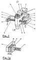
- FIG. 1 shows a scanning device which is attached by means of a carrier 10 to an arm or slide, not shown in the drawing, which is adjustable in larger steps for the purpose of rough control when scanning the information carrier.
- the elements proposed for the fine drive and the position control of the scanning head with the invention can be seen in detail from the drawing.
- the scanning head 11 used to read out the information hides the light source and the optics in its interior for generating the light beam emerging upwards in the drawing and thus the light spot on the carrier surface.
- the scanning head also houses a beam splitter for separating the reflected light from the emitted light, and an assembly consisting of semiconductor segments which convert the reflected light into electrical signals.
- the optical system 11 a of the scanning head 11 is axially adjustably connected to the head carrier 13 via leaf springs 12.
- the optical system 11 a for focusing the light spot on the carrier surface can be adjusted in the axial direction by means of a preferably electromagnetic device (not shown).
- This fine drive consists essentially of a magnetic circuit with the on the carrier 10 brought permanent magnets 15, at the ends provided pole pieces 16 and the coil 17 housed in the rear housing part 11b.
- the scanning head can be pivoted against the action of resilient resetting elements, namely the springs 18.
- the symmetrical and biased springs 18 are clamped between the brackets 19 and the scanning head housing 11 b.
- Piezoelectric transducers 20 and 21 are provided between the ends of the brackets 19 and the springs 18.
- the springs 18 are supported on the piezoelectric transducers via pressure and fastening plates 23 in order to generate uniform surface pressures and to fix them.
- the same output voltages U 1 and U 2 are generated by the action of pressure by means of the piezoelectric transducers 20 and 21.
- the pressure loads on the transducers 20 and 21 change, which results in different output voltages U and U 2 .
- the output voltages are therefore a measure of the radial deflection of the head.
- the converters 20 and 21, which are divided into two individual elements according to FIG. 1, can also be combined with one another to form a compact element, as is indicated in FIG. 1A.
- two transducers 20 'and 21' are combined to form a compact element which is provided between the holder 19 and the pressure and fastening plate 23.
- a voltage U s may be applied to the converter 20 'either as a correction variable or as a wobble voltage, while the voltage U E arising at the converter 21' can be used as a control variable.
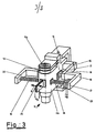
- FIG. 3 A modification of the scanning head acc. Fig. 1 is shown in Fig. 3. The same parts are labeled with the same numbers as in Fig. 1.
- a piezoelectric bending oscillator 25 is fixedly attached at one end to the housing 11 b of the scanning head in the case of the one according to FIG. 3.
- the other end of the bending vibrator 25 is free and can be set into bending vibrations in the direction of the double arrow S when an alternating voltage U s is applied. Since the scanning head 11 is resiliently mounted between the springs 18, it will also be vibrated in response to the vibrations S.
- the scanning head 11 is arranged by means of the head carrier 13 so as to be pivotable about the axis 14 against the action of the springs 18, with a fine drive for radial deflection acting on the head carrier 13 and thus the scanning head 11.
- this fine drive is realized by the electromagnetic circuit 15, 16 and 17.
- the threshold device for switching from fine control to rough control is not shown in the drawing.
Landscapes
- Optical Recording Or Reproduction (AREA)
- Moving Of The Head For Recording And Reproducing By Optical Means (AREA)
- Moving Of The Head To Find And Align With The Track (AREA)
- Mechanical Optical Scanning Systems (AREA)
Description
- Die Erfindung betrifft eine Lesevorrichtung der im Oberbegriff des Hauptanspruchs angegebenen Art.
- Solche Lesevorrichtungen, auch kurz optische Abtaster genannt, dienen dem Auslesen von Audio- und/oder Video-Informationen, die auf einer Audio- bzw. Videoplatte gespeichert sind. Sie sind grundsätzlich auch zum Auslesen anderer optisch lesbarer Daten für die Datenverarbeitung geeignet. Das Prinzip der Speicherung und des Auslesens optisch lesbarer Daten ist allgemein erläutert in Philips Technical Review, Band 40, Nr. 6, 1982, Seiten 151-155.
- Als Datenträger werden üblicherweise plattenförmige, rotierende Aufzeichnungsträger, sogenannte Bildspeicher- oder Videoplatten verwendet. Anwendbar sind jedoch auch andere Speichermedien, soweit diese eine lichtreflektierende Fläche zur Speicherung optisch lesbarer Daten aufweisen.
- Die Lesevorrichtung besteht im wesentlichen aus einem Abtastkopf mit einer Lichtquelle, in der Regel einem Laserlicht erzeugenden Halbleiter, sowie einer Optik, welche ein oder mehrere Lichtflecke auf der Trägerfläche erzeugt. Der Abtastkopf weist ferner Mittel, z.B. Strahlenteiler, zur Trennung des reflektierten Lichtes vom ausgesendeten Licht sowie Detektionselemente zur Umwandlung des reflektierten Lichtes in elektrische Grössen auf.
- Da die Spurendichte ausserordentlich hoch ist, muss der Abtastkopf der Spur mit grosser Präzision, nämlich einer Toleranz von ± 0,1 gm, der aufgezeichneten Spur folgen. Diese Genauigkeit ist durch mechanische Präzision nicht erreichbar, da allein die durch Exzentrizität des Aufzeichnungsträgers und des Wiedergabegerätes bedingten Abweichungen ein mehrfaches des oben angegebenen Toleranzbereiches (bis zu 300 µm) betragen.
- Es sind darum Regeleinrichtungen notwendig, welche den Abtastkopf gesteuert von der aufgezeichneten Spur nachführen.
- Es ist bekannt, zur Nachführung des den Abtastkopf tragenden Armes in grösseren Schritten eine Grobsteuerung sowie zur Nachführung des verschwenkbar am Arm gelagerten Kopfes in kleineren Schritten eine Feinsteuerung vorzusehen. Hierdurch werden die bei der Feinsteuerung zu bewegenden effektiven Massen klein gehalten, wodurch eine rasche Nachregelung ermöglicht wird.
- Wenn die Auslenkung des nachgeführten Abtastkopfes einen vorgegebenen Schwellwert übersteigt, erfolgt eine Umschaltung von Feinauf Grobsteuerung.
- Bei einem bekannten Prinzip, bei welchem der Abtastkopf in einer definierten Mittellage gehalten und gegen die rückstellende Wirkung einer Elastizität ausgelenkt wird, ist ein Mass für den Schwellwert der Maximalwert des elektrischen Stromes, welche die Spule für den Radial-Feinantrieb durchfliesst.
- Bei einer Anordnung dieser Art können im Regelkreis auftretende schmale Impulse den Schwellwert zur Einschaltung des Grobantriebes bereits überschreiten, obwohl wegen der geringen Impulsbreite und bedingt durch die mechanische Trägheit des Abtastkopfes letzterer noch nicht den mechanischen Schwellwert für die Umschaltung von Feinantrieb auf Grobantrieb erreicht hat. Um dies zu vermeiden, müssen derartige Impulse unterdrückt, z.B. mittels eines Tiefpassfilters von der Schwellwert-Einrichtung ferngehalten werden. Auf der anderen Seite dürfen Impulse, die einer tatsächlichen Radial-Fehlerabweichung des Lichtfleckes gegenüber der Spur entsprechen, nicht durch derartige Tiefpassfilter beeinflusst werden. Folglich muss bei derartigen Schwellwerteinrichtungen ein Kompromiss zwischen Unterdrückung von Störgrössen und der Übertragung gewünschter Korrektursignale getroffen werden.
- Dieser Kompromiss braucht nicht eingegangen zu werden, wenn die tatsächliche Abweichung des Abtastkopfes von der Soll-Lage oder einer Referenzlage ermittelt wird. Bei Analog-Plattenspielern (z.B. Type SL3 oder SL5 der Fa. Technics) wird die Abweichung des Tonabnehmers unmittelbar mittels einer Lichtschrankenanordnung festgestellt, bei welcher am beweglichen Tonarm eine Blende angebracht ist, welche sich im Lichtweg zwischen einer Lichtquelle und einem 2-Segment-Fotoelement befindet. Die Lichtblende und die Fotoelemente sind so angeordnet, dass die Segmente bei Abweichung des Tonabnehmers von der Referenzlage unterschiedlich stark beleuchtet werden. Aus den beiden elektrischen Signalen der Fotoelemente lässt sich ein Regelsignal zur radialen Lagekorrektur des Tonabnehmers ermitteln. Im Regelkreis auftretende Impulse, welche eine Bewegung des Tonabnehmers nicht zur Folge haben, werden anders als bei der oben erläuterten Anordnung nicht ermittelt und können folglich nicht zu einer fehlerhaften Korrektur führen.
- Eine derartige Lichtschrankenanordnung ist wegen der erforderlicehn Präzision relativ aufwendig und wegen der Gefahr unterschiedlicher Verschmutzung oder Alterung der Fotoelement-Segmente auch störanfällig. Ausserdem kann diese Lichtschrankenanordnung selbst nicht dazu benutzt werden, gewünschte Auslenkungen des Abtastkopfes gesteuert hervorzurufen.
- Mit der vorliegenden Erfindung soll für einen Abtastkopf der erläuterten Art eine Schwellwert- einrichtung geschaffen werden, welche einerseits gegen Störimpulse und andererseits gegen Verschmutzung oder Alterung unempfindlicher ist.
- Die Lösung der vorliegenden Erfindung geht von einer aus der DE-A-29 18 919 bekannten Lesevorrichtung aus, deren für die vorliegende Erfindung notwendige Merkmale im Oberbegriff des Hauptanspruchs im einzelnen angegeben sind.
- Bei dieser bekannten Lesevorrichtung erzeugt die Auslenkung des Abtastkopfes in einem piezoelektrischen Wandler, welcher im Kraftfluss zwisehen Abtastkopf und einem einseitig gehaltenen elastisch federnden Rückstellglied, nämlich einer einerends eingespannten Blattfeder, angeordnet ist, ein der Auslenkung des Abtastkopfes entsprechendes Signal, welches bei dieser Anordnung der dynamischen Rückkopplung für die Servospursteuerung dient.
- Nach dem erfindungsgemässen Vorschlag, wie er im Kennzeichen des Hauptanspruchs definiert ist, wird dieser elektrodynamische Wandler als Schwellwerteinrichtung eingesetzt, welche eine Umschaltung von Fein- auf Grobsteuerung bewirkt, wenn die Auslenkung des nachgeführten Abtastkopfes einen vorgegebenen Schwellwert übersteigt. Hierbei wird aus der elektrischen Ausgangsgrösse des Wandlers die die Umsteuerung von Fein- auf Grobsteuerung bewirkende Steuergrösse abgeleitet.
- Eine derartige Schwellwerteinrichtung ist weitgehend unempfindlich gegen Störimpulse. Soweit piezoelektrische Bauelemente als elektromechanische Wandler verwendet werden, scheiden Fehler wegen Verschmutzung und Alterung nahezu vollständig aus.
- Bei einem bevorzugten Ausführungsbeispiel, bei welchem der Abtastkopf mittels beidseitig angeordneter Federelemente in definierter Lage zwischen zwei Halterungen gehalten wird, ist zwischen jedem der beiden Federelemente und der jeweiligen Halterung ein eigener Wandler angeordnet. Die Ausgangsspannungen der beiden Wandler werden hierbei einer Differenzschaltung zugeführt, welche die Steuergrösse aus den beiden Ausgangsspannungen herleitet.
- Für die Realisierung der Erfindung eignen sich vorzugsweise piezoelektrische Wandler, die in Form von einfachen Longitudinal-Schwingern ausgebildet sind. Bei Auslenkungen des Feintriebs entstehen in den beidseitig angeordneten Wandlern Druck- bzw. Zugkräfte, welche entgegengesetzt gerichtete Piezospannungen zur Folge haben, die in der oben erwähnten Differenzschaltung zur Ermittlung der Steuergrösse miteinanderverknüpftwerden.
- Bei dieser Anordnung kann in Weiterbildung der Erfindung nur einer der beiden Wandler zur Bestimmung der radialen Abweichung des Abtastkopfes benutzt werden, während der andere Wandler als Schwingungserzeuger dient. Die Ausgangsspannung des erstgenannten Wandlers muss in diesem Fall mit einer der Mittellage des Abtastkopfes entsprechenden Referenzspannung verglichen werden. Dem zweiten, als Schwingungserzeuger oder Sender dienenden Wandler können definierte elektrische Kontrollsignale zugeführt werden, welche den Abtastkopf radial auslenken. Durch Zusammenwirken von Schwingungserzeuger bzw. Sender und Empfangswandler könnnen evtl. entstehende Asymmetrien des optischen Systems kompensiert werden.
- Diese Anordnung eignet sich dazu, dem Abtastkopf eine niederfrequente Schwingung mit einer Frequenz von 600 Hz und einer Amplitude von ± 0,05 gm zu überlagern wie dies in der eingangs zitierten Veröffentlichung Philips Technical Review, Seite 154 erläutert ist. Die niederfrequente Kontrollschwingung wird hierbei mittels des vorhandenen Mechanismus für den Feinantrieb erzeugt. Diese Verfahrensweise hat den Nachteil, dass einerseits der vergleichsweise empfindliche Feinantrieb mit verschiedenen Steuersignalen beaufschlagt wird. Andererseits gehen auch in die Kontrollschwingungen Fehler ein, welche durch die Charakteristik des Feintriebs bedingt sind.
- Diese Nachteile hat die erfindungsgemässe Lösung nicht, bei welcher Antrieb und Fehlerkorrektur voneinander getrennt sind.
- Der Gegenstand der Erfindung sowie weitere an dieser Stelle noch nicht erläuterte Merkmale und Massnahmen sind nachstehend anhand von Ausführungsbeispielen, die zeichnerisch dargestellt sind, im einzelnen erläutert. In den Zeichnungen zeigen:
- Fig. 1 perspektivische Darstellung eines erfindungsgemäss ausgebildeten Abtastkopfes nach einem ersten Ausführungsbeispiel,
- Fig. a a perspektivische Darstellung eines piezoelektrischen Wandlers, bei welchem Schwingungserzeuger und Empfänger zu einer Einheit kombiniert sind,
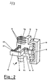
- Fig. 2 perspektivische Darstellung des Abtastkopfes gemäss Figur 1 in einer gegenüber dieser um 90° gedrehten Ansicht,
- Fig. 3 perspektivische Darstellung eines erfindungsgemäss gestalteten Abtastkopfes nach einem zweiten Ausführungsbeispiel.
- Die perspektivische Darstellung in Fig. 1 zeigt eine Abtastvorrichtung, welche mittels eines Trägers 10 an einem zeichnerisch nicht dargestellten Arm oder Schlitten angebracht ist, der zum Zwecke der Grobsteuerung in grösseren Schritten bei der Abtastung des Informationsträgers verstellbar ist. Aus der Zeichnung im Detail erkennbar sind die für den Feinantrieb und die Lageregelung des Abtastkopfes mit der Erfindung vorgeschlagenen Elemente.
- Der dem Auslesen der Information dienende Abtastkopf 11 birgt in seinem Inneren die Lichtquelle und die Optik zur Erzeugung des in der Zeichnung nach oben austretenden Lichtbündels und damit des Lichtfleckes auf der Trägerfläche. Im Abtastkopf untergebracht ist ferner ein Strahlenteiler zur Trennung des reflektierten Lichtes vom ausgesendeten Lichtes sowie eine Baugruppe, bestehend aus Halbleitersegmenten, welche das reflektierte Licht in elektrische Signale umwandeln. Das optische System 11 a des Abtastkopfes 11 ist über Blattfedern 12 mit dem Kopfträger 13 axial verstellbar verbunden. Mittels einer nicht dargestellten, vorzugsweise elektromagnetischen Einrichtung lässt sich das optische System 11 a zur Fokussierung des Lichtfleckes auf der Trägerfläche in axialer Richtung verstellen. Der Kopfträger 13, mit welchem das Gehäuse 11 b des Abtastkopfes 11 fest verbunden ist, ist um die Drehachse 14 mittels des nachstehend noch erläuterten Feinantriebs verschwenkbar. Dieser Feinantrieb besteht im wesentlichen aus einem magnetischen Kreis mit dem am Träger 10 angebrachten Permanentmagneten 15, an dessen Enden vorgesehenen Polschuhen 16 und der im rückwärtigen Gehäuseteil 11b untergebrachten Spule 17. Je nach Bestromung der Spule 17 lässt sich der Abtastkopf gegen die Wirkung elastisch federnder Rückstellglieder, nämlich der Federn 18, verschwenken. Die symmetrisch ausgebildeten und vorgespannten Federn 18 sind zwischen den Halterungen 19 und dem Abtastkopfgehäuse 11 b eingespannt. Zwischen den Enden der Halterungen 19 und den Federn 18 sind druck- bzw. zugempfindliche piezoelektrische Wandler 20 und 21 vorgesehen. Zur Erzeugung gleichmässiger Flächendrücke und Festlegung stützen sich die Federn 18 über Druck- und Befestigungsplatten 23 auf den piezoelektrischen Wandlern ab. Bei symmetrischer Positionierung des Abtastkopfes werden durch Druckeinwirkung mittels der piezoelektrischen Wandler 20 und 21 gleiche Ausgangsspannungen U, und U2 erzeugt. Bei Auslenkung des Abtastkopfes aus einer Mittellage verändern sich die Druckbelastungen der Wandler 20 und 21, was unterschiedliche Ausgangsspannungen U, und U2 zur Folge hat. Die Ausgangsspannungen sind also ein Mass für die radiale Auslenkung des Kopfes.
- Durch Anlegen einer Spannung, z.B. der Spannung Ui, an den Wandler 20 lässt sich eine willkürliche Dickenänderung des Wandlers und damit eine willkürliche Auslenkung des Kopfes 11 erreichen. Diese Eigenschaft wird in Weiterbildung der Erfindung dazu ausgenutzt, den Abtastkopf und damit das optische System gesteuert auszulenken.
- Die Wandler 20 und 21, die nach Fig. 1 in zwei Einzelelemente aufgeteilt sind, können auch zu einem kompakten Element miteinander kombiniert werden, wie dies in Fig. 1 A angedeutet ist. Bei dieser Anordnung sind zwei Wandler 20' und 21' zu einem kompakten Element kombiniert, das zwischen Halterung 19 und Druck- und Befestigungsplatte 23 vorgesehen ist. An den Wandler 20' möge eine Spannung Us entweder als Korrekturgrösse oder als Wobbelspannung angelegt werden, während die am Wandler 21' entstehende Spannung UE als Steuergrösse ausgenutzt werden kann.
- Eine Abwandlung des Abtastkopfes gem. Fig. 1 ist in Fig. 3 dargestellt. Gleiche Teile sind mit gleichen Ziffern wie in Fig. 1 bezeichnet. Anstelle des Wandlers 20 bei dem Ausführungsbeispiel in Fig. 1 ist bei demjenigen gemäss Fig. 3 unmittelbar am Gehäuse 11 b des Abtastkopfes ein piezoelektrischer Biegeschwinger 25 mit einem Ende fest angebracht. Das andere Ende des Biegeschwingers 25 ist frei und kann bei Anlegen einer Wechselspannung Us in Richtung des Doppelpfeiles S in Biegeschwingungen versetzt werden. Da der Abtastkopf 11 zwischen den Federn 18 elastisch gelagert ist, wird er als Reaktion auf die Schwingungen S gleichfalls in Schwingungen versetzt werden. Der Abtastkopf 11 ist mittels des Kopfträgers 13 um die Achse 14 gegen die Wirkung der Federn 18 verschwenkbar angeordnet, wobei auf den Kopfträger 13 und damit den Abtastkopf 11 ein Feinantrieb zur radialen Auslenkung einwirkt. Beim Ausführungsbeispiel nach Fig. 1 und 3 ist dieser Feinantrieb realisiert durch den elektromagnetischen Kreis 15, 16 und 17.
- Die Schwellwerteinrichtung zur Umschaltung von Feinsteuerung auf Grobsteuerung ist nicht zeichnerisch dargestellt. Als Detektionselement dient eine an sich bekannte Anordnung eines 4-Segment-Fotoelementes, welches sowohl die Data-Informationen als auch die Fehlersignale ausliest.
-
- 10 Träger
- 11 Abtastkopf
- 11 a optisches System
- 11 b Gehäuse
- 12 Blattfedern
- 13 Kopfträger
- 14 Drehachse
- 15 Permanentmagnet
- 16 Polschuhe
- 17 Spule
- 18 elastisch-federnde Rückstellglieder, Federn
- 19 Halterungen
- 20 piezoelektrische Wandler, Schwingungserzeuger
- 21 piezoelektrischer Wandler, Empfänger
- 23 Druck- und Befestigungsplatte
- 24 Befestigungsarm
- 25 piezoelektrischer Biegeschwinger
- S Schwingungsrichtung des Biegeschwingers 25
Claims (6)
Applications Claiming Priority (2)
| Application Number | Priority Date | Filing Date | Title |
|---|---|---|---|
| DE3324861 | 1983-07-09 | ||
| DE3324861A DE3324861C2 (de) | 1983-07-09 | 1983-07-09 | Lesevorrichtung zum optischen Abtasten von auf einem bewegten plattenförmigen Träger aufgezeichneten Informationen |
Related Child Applications (1)
| Application Number | Title | Priority Date | Filing Date |
|---|---|---|---|
| EP86113775.0 Division-Into | 1984-06-13 |
Publications (2)
| Publication Number | Publication Date |
|---|---|
| EP0134428A1 EP0134428A1 (de) | 1985-03-20 |
| EP0134428B1 true EP0134428B1 (de) | 1988-01-27 |
Family
ID=6203615
Family Applications (2)
| Application Number | Title | Priority Date | Filing Date |
|---|---|---|---|
| EP86113775A Expired - Lifetime EP0249653B1 (de) | 1983-07-09 | 1984-06-13 | Lesevorrichtung zum optischen Abtasten von auf einem beweglichen plattenförmigen Träger aufgezeichneten Informationen |
| EP84106715A Expired EP0134428B1 (de) | 1983-07-09 | 1984-06-13 | Lesevorrichtung zum optischen Abtasten von auf einem bewegten plattenförmigen Träger aufgezeichneten Informationen |
Family Applications Before (1)
| Application Number | Title | Priority Date | Filing Date |
|---|---|---|---|
| EP86113775A Expired - Lifetime EP0249653B1 (de) | 1983-07-09 | 1984-06-13 | Lesevorrichtung zum optischen Abtasten von auf einem beweglichen plattenförmigen Träger aufgezeichneten Informationen |
Country Status (5)
| Country | Link |
|---|---|
| US (1) | US4718050A (de) |
| EP (2) | EP0249653B1 (de) |
| JP (2) | JPS6063734A (de) |
| DE (1) | DE3324861C2 (de) |
| DK (1) | DK157956C (de) |
Families Citing this family (10)
| Publication number | Priority date | Publication date | Assignee | Title |
|---|---|---|---|---|
| JPS6095735A (ja) * | 1983-10-31 | 1985-05-29 | Hitachi Ltd | 対物レンズ駆動装置 |
| DE3500671A1 (de) * | 1985-01-11 | 1986-07-17 | Deutsche Thomson-Brandt Gmbh, 7730 Villingen-Schwenningen | Lesevorrichtung zum optischen abtasten von auf einem beweglichen plattenfoermigen traeger aufgezeichneten informationen |
| JPH01201831A (ja) * | 1988-02-05 | 1989-08-14 | Olympus Optical Co Ltd | 光学的情報記録再生装置 |
| US5220543A (en) * | 1989-02-14 | 1993-06-15 | Victor Company Of Japan, Ltd. | Compact optical disc recording/reproducing system |
| JP2593941B2 (ja) * | 1989-08-19 | 1997-03-26 | 富士通株式会社 | 光ディスク装置のアクチュエータオフセット除去装置 |
| DE4135908A1 (de) * | 1991-10-31 | 1993-05-06 | Deutsche Thomson-Brandt Gmbh, 7730 Villingen-Schwenningen, De | Aktuatoranordnung |
| US6009061A (en) * | 1994-08-25 | 1999-12-28 | Discovision Associates | Cartridge-loading apparatus with improved base plate and cartridge receiver latch |
| US5724331A (en) | 1994-08-25 | 1998-03-03 | Discovision Associates | Disk drive system having improved cartridge-loading apparatus including direct drive gear train and methods for making and operating same |
| KR0179258B1 (ko) * | 1996-01-05 | 1999-04-15 | 구자홍 | 광디스크 기록재생장치 |
| US6185030B1 (en) * | 1998-03-20 | 2001-02-06 | James W. Overbeck | Wide field of view and high speed scanning microscopy |
Citations (1)
| Publication number | Priority date | Publication date | Assignee | Title |
|---|---|---|---|---|
| DE2918919A1 (de) * | 1978-05-10 | 1979-11-22 | Olympus Optical Co | Vorrichtung zum auslesen optischer informationen aus einem aufzeichnungstraeger |
Family Cites Families (15)
| Publication number | Priority date | Publication date | Assignee | Title |
|---|---|---|---|---|
| US4282598A (en) * | 1972-10-24 | 1981-08-04 | Discovision Associates | Video disc read back scanner |
| SE7405076L (sv) * | 1974-04-16 | 1975-10-17 | Erik Gerhard Natanel Westberg | Optiskt massdataminne. |
| DE2611617C2 (de) * | 1976-03-19 | 1983-10-20 | Philips Patentverwaltung Gmbh, 2000 Hamburg | Elektrisch gesteuerte Einstellvorrichtung für einen digital und analog ablenkgesteuerten Lichtstrahl |
| NL7808638A (nl) * | 1978-08-22 | 1980-02-26 | Philips Nv | Inrichting voor het uitlezen van een schijfvormige re- gistratiedrager. |
| NL7810386A (nl) * | 1978-10-17 | 1980-04-21 | Philips Nv | Optische leesinrichting voor het uitlezen van een schijfvormige registratiedrager. |
| NL7812111A (nl) * | 1978-12-13 | 1980-06-17 | Philips Nv | Inrichting voor het optisch uitlezen van een schijf- vormige registratiedrager, in het bijzonder het snel opzoeken van een gewenst programmagedeelte. |
| JPS55146634A (en) * | 1979-04-26 | 1980-11-15 | Olympus Optical Co Ltd | Objective lens driver |
| JPS55153138A (en) * | 1979-05-14 | 1980-11-28 | Mitsubishi Electric Corp | Optical pickup unit |
| JPS6030576B2 (ja) * | 1979-08-21 | 1985-07-17 | エヌエスケ−・ワ−ナ−株式会社 | シ−トベルトリトラクタの巻取力軽減機構 |
| JPS56170537U (de) | 1980-05-16 | 1981-12-16 | ||
| NL8003305A (nl) * | 1980-06-06 | 1982-01-04 | Philips Nv | Inrichting voor het opzoeken van een gewenst informa- tiespoor. |
| JPS6215864Y2 (de) * | 1980-08-04 | 1987-04-22 | ||
| NL8103305A (nl) * | 1981-07-10 | 1983-02-01 | Philips Nv | Opto-elektronische inrichting voor het met een stralingsbundel inschrijven en/of uitlezen van registratiesporen. |
| NL8105347A (nl) * | 1981-11-26 | 1983-06-16 | Philips Nv | Inrichting voor het optisch aftasten van een schijfvormige registratiedrager. |
| JPS58166567A (ja) * | 1982-03-26 | 1983-10-01 | Matsushita Electric Ind Co Ltd | 情報トラックの検索装置 |
-
1983
- 1983-07-09 DE DE3324861A patent/DE3324861C2/de not_active Expired
-
1984
- 1984-06-13 EP EP86113775A patent/EP0249653B1/de not_active Expired - Lifetime
- 1984-06-13 EP EP84106715A patent/EP0134428B1/de not_active Expired
- 1984-07-09 US US06/628,770 patent/US4718050A/en not_active Expired - Fee Related
- 1984-07-09 JP JP59140775A patent/JPS6063734A/ja active Pending
- 1984-07-09 DK DK337384A patent/DK157956C/da not_active IP Right Cessation
-
1992
- 1992-06-05 JP JP4145508A patent/JPH0831214B2/ja not_active Expired - Lifetime
Patent Citations (1)
| Publication number | Priority date | Publication date | Assignee | Title |
|---|---|---|---|---|
| DE2918919A1 (de) * | 1978-05-10 | 1979-11-22 | Olympus Optical Co | Vorrichtung zum auslesen optischer informationen aus einem aufzeichnungstraeger |
Also Published As
| Publication number | Publication date |
|---|---|
| DK157956C (da) | 1990-08-13 |
| EP0249653A2 (de) | 1987-12-23 |
| EP0249653A3 (en) | 1988-01-07 |
| EP0249653B1 (de) | 1991-01-09 |
| US4718050A (en) | 1988-01-05 |
| JPH0831214B2 (ja) | 1996-03-27 |
| DK337384A (da) | 1985-01-10 |
| EP0134428A1 (de) | 1985-03-20 |
| DE3324861A1 (de) | 1985-01-17 |
| DK157956B (da) | 1990-03-05 |
| DE3324861C2 (de) | 1986-02-13 |
| DK337384D0 (da) | 1984-07-09 |
| JPS6063734A (ja) | 1985-04-12 |
| JPH0644597A (ja) | 1994-02-18 |
Similar Documents
| Publication | Publication Date | Title |
|---|---|---|
| DE2918919C2 (de) | ||
| DE2645393C2 (de) | Folgespiegelvorrichtung, insbesondere zum Gebrauch in einem Videoplattenspieler | |
| DE3686589T2 (de) | Spurfolgesystem zum steuerbaren projizieren eines optischen strahles auf eine optische platte. | |
| DE2661100C2 (de) | ||
| DE3015042C2 (de) | Verstelleinrichtung für das Beleuchtungs-Objektiv eines Wiedergabegeräts für plattenförmige, optisch lesbare, rotierende Aufzeichnungsträger | |
| DE68919893T2 (de) | Optische Kopfanordnungen für Plattenspieler. | |
| DE4391073C2 (de) | Abgesetzter Feinpositioniermechanismus | |
| DE4029040C2 (de) | ||
| DE69521186T2 (de) | Galvanospiegel und damit versehenes Laufwerk für optische Platten | |
| DE69111648T2 (de) | Mechanismus zum Detektieren des Rotationswinkels eines Spiegels. | |
| DE3931500C2 (de) | ||
| EP0129760B1 (de) | Spurfolgesystem mit einem optischen Abtaster für ein Audio- oder Video-Plattenwiedergabegerät | |
| EP0134428B1 (de) | Lesevorrichtung zum optischen Abtasten von auf einem bewegten plattenförmigen Träger aufgezeichneten Informationen | |
| DE69228371T2 (de) | Optisches Plattengerät mit reduzierter Abmessung | |
| DE3486252T2 (de) | Antriebsanordnung zur Anwendung in einem optischen Plattenspieler oder Aufzeichnungsgerät und Plattenspieler oder Aufzeichnungsgerät mit einer gleichen Anordnung. | |
| DE2503952C2 (de) | Vorrichtung zum Auslesen eines Aufzeichnungsträgers, auf dem Information in einer optisch auslesbaren Struktur angebracht ist | |
| DE3619515A1 (de) | Optische informations-aufzeichnungs- und/oder -wiedergabeeinrichtung | |
| DE3780866T2 (de) | Optisches informations-aufzeichnungs- und wiedergabegeraet. | |
| DE3887228T2 (de) | Verfahren und Gerät für optische Aufnahme und Wiedergabe. | |
| DE68912149T2 (de) | Optisches Informationsverarbeitungsgerät. | |
| EP0303646B1 (de) | Gerät zur wiedergabe von daten | |
| EP0822542A2 (de) | Gerät zum Lesen und/oder Beschreiben optischer Aufzeichnungsträger | |
| DE69418925T2 (de) | Gerät zum Aufzeichnen und/oder zum Wiedergeben von Informationen mittels eines Strahlungsbündels | |
| DD298448A5 (de) | Abtastvorrichtung | |
| DE69624161T2 (de) | Abtastvorrichtung einer optischen Platte |
Legal Events
| Date | Code | Title | Description |
|---|---|---|---|
| PUAI | Public reference made under article 153(3) epc to a published international application that has entered the european phase |
Free format text: ORIGINAL CODE: 0009012 |
|
| AK | Designated contracting states |
Designated state(s): BE CH FR GB IT LI LU NL |
|
| 17P | Request for examination filed |
Effective date: 19850411 |
|
| 17Q | First examination report despatched |
Effective date: 19860624 |
|
| ITF | It: translation for a ep patent filed | ||
| GRAA | (expected) grant |
Free format text: ORIGINAL CODE: 0009210 |
|
| AK | Designated contracting states |
Kind code of ref document: B1 Designated state(s): BE CH FR GB IT LI LU NL |
|
| GBT | Gb: translation of ep patent filed (gb section 77(6)(a)/1977) | ||
| ET | Fr: translation filed | ||
| PLBE | No opposition filed within time limit |
Free format text: ORIGINAL CODE: 0009261 |
|
| STAA | Information on the status of an ep patent application or granted ep patent |
Free format text: STATUS: NO OPPOSITION FILED WITHIN TIME LIMIT |
|
| 26N | No opposition filed | ||
| ITTA | It: last paid annual fee | ||
| EPTA | Lu: last paid annual fee | ||
| PGFP | Annual fee paid to national office [announced via postgrant information from national office to epo] |
Ref country code: GB Payment date: 19950524 Year of fee payment: 12 |
|
| PGFP | Annual fee paid to national office [announced via postgrant information from national office to epo] |
Ref country code: LU Payment date: 19950601 Year of fee payment: 12 |
|
| PGFP | Annual fee paid to national office [announced via postgrant information from national office to epo] |
Ref country code: FR Payment date: 19950616 Year of fee payment: 12 |
|
| PGFP | Annual fee paid to national office [announced via postgrant information from national office to epo] |
Ref country code: CH Payment date: 19950619 Year of fee payment: 12 |
|
| PGFP | Annual fee paid to national office [announced via postgrant information from national office to epo] |
Ref country code: NL Payment date: 19950628 Year of fee payment: 12 |
|
| PGFP | Annual fee paid to national office [announced via postgrant information from national office to epo] |
Ref country code: BE Payment date: 19950630 Year of fee payment: 12 |
|
| PG25 | Lapsed in a contracting state [announced via postgrant information from national office to epo] |
Ref country code: GB Effective date: 19960613 Ref country code: LU Free format text: LAPSE BECAUSE OF NON-PAYMENT OF DUE FEES Effective date: 19960613 |
|
| PG25 | Lapsed in a contracting state [announced via postgrant information from national office to epo] |
Ref country code: BE Effective date: 19960630 Ref country code: CH Effective date: 19960630 Ref country code: LI Effective date: 19960630 |
|
| BERE | Be: lapsed |
Owner name: DEUTSCHE THOMSON-BRANDT G.M.B.H. Effective date: 19960630 |
|
| PG25 | Lapsed in a contracting state [announced via postgrant information from national office to epo] |
Ref country code: NL Effective date: 19970101 |
|
| GBPC | Gb: european patent ceased through non-payment of renewal fee |
Effective date: 19960613 |
|
| REG | Reference to a national code |
Ref country code: CH Ref legal event code: PL |
|
| PG25 | Lapsed in a contracting state [announced via postgrant information from national office to epo] |
Ref country code: FR Effective date: 19970228 |
|
| NLV4 | Nl: lapsed or anulled due to non-payment of the annual fee |
Effective date: 19970101 |
|
| REG | Reference to a national code |
Ref country code: FR Ref legal event code: ST |