EP0134765B1 - Véhicule moteur comportant une conduite pour l'air de refroidissement du radiateur dans lequel passe le fluide de refroidissement du moteur - Google Patents
Véhicule moteur comportant une conduite pour l'air de refroidissement du radiateur dans lequel passe le fluide de refroidissement du moteur Download PDFInfo
- Publication number
- EP0134765B1 EP0134765B1 EP84830240A EP84830240A EP0134765B1 EP 0134765 B1 EP0134765 B1 EP 0134765B1 EP 84830240 A EP84830240 A EP 84830240A EP 84830240 A EP84830240 A EP 84830240A EP 0134765 B1 EP0134765 B1 EP 0134765B1
- Authority
- EP
- European Patent Office
- Prior art keywords
- section
- radiator
- bodywork part
- motor vehicle
- bumper
- Prior art date
- Legal status (The legal status is an assumption and is not a legal conclusion. Google has not performed a legal analysis and makes no representation as to the accuracy of the status listed.)
- Expired
Links
- 238000001816 cooling Methods 0.000 title claims description 13
- 239000007788 liquid Substances 0.000 title claims description 5
- 239000002826 coolant Substances 0.000 title description 2
- 230000000452 restraining effect Effects 0.000 claims description 2
- 230000001010 compromised effect Effects 0.000 description 1
- 230000000694 effects Effects 0.000 description 1
- 239000000463 material Substances 0.000 description 1
- 239000002991 molded plastic Substances 0.000 description 1
- 238000005192 partition Methods 0.000 description 1
- 239000007779 soft material Substances 0.000 description 1
Images


Classifications
-
- B—PERFORMING OPERATIONS; TRANSPORTING
- B62—LAND VEHICLES FOR TRAVELLING OTHERWISE THAN ON RAILS
- B62D—MOTOR VEHICLES; TRAILERS
- B62D35/00—Vehicle bodies characterised by streamlining
- B62D35/005—Front spoilers
-
- B—PERFORMING OPERATIONS; TRANSPORTING
- B60—VEHICLES IN GENERAL
- B60K—ARRANGEMENT OR MOUNTING OF PROPULSION UNITS OR OF TRANSMISSIONS IN VEHICLES; ARRANGEMENT OR MOUNTING OF PLURAL DIVERSE PRIME-MOVERS IN VEHICLES; AUXILIARY DRIVES FOR VEHICLES; INSTRUMENTATION OR DASHBOARDS FOR VEHICLES; ARRANGEMENTS IN CONNECTION WITH COOLING, AIR INTAKE, GAS EXHAUST OR FUEL SUPPLY OF PROPULSION UNITS IN VEHICLES
- B60K11/00—Arrangement in connection with cooling of propulsion units
- B60K11/08—Air inlets for cooling; Shutters or blinds therefor
-
- Y—GENERAL TAGGING OF NEW TECHNOLOGICAL DEVELOPMENTS; GENERAL TAGGING OF CROSS-SECTIONAL TECHNOLOGIES SPANNING OVER SEVERAL SECTIONS OF THE IPC; TECHNICAL SUBJECTS COVERED BY FORMER USPC CROSS-REFERENCE ART COLLECTIONS [XRACs] AND DIGESTS
- Y02—TECHNOLOGIES OR APPLICATIONS FOR MITIGATION OR ADAPTATION AGAINST CLIMATE CHANGE
- Y02T—CLIMATE CHANGE MITIGATION TECHNOLOGIES RELATED TO TRANSPORTATION
- Y02T10/00—Road transport of goods or passengers
- Y02T10/80—Technologies aiming to reduce greenhouse gasses emissions common to all road transportation technologies
- Y02T10/82—Elements for improving aerodynamics
Definitions
- the present invention relates to motor vehicles having a front bodywork part, a front bumper located in front of the front bodywork part, a radiator for the liquid of the engine cooling circuit supported by the front bodywork part, and a conveyor for air for cooling the radiator located in front of the radiator.
- This document shows a front grill for cooling the radiator which can be resiliently moved rearwardly with respect to the remaining portion of the front body work part by a thrust exerted in this direction in case of a minor frontal collision.
- the object of the present invention is to give a solution to the previously mentioned problem in the case where the conveyor for the cooling air for the radiator is not exposed to the exterior of the bodywork but placed and hidden behind a front end thereof from which the front bumper projects forwardly.
- this object is achieved by virtue of a motor vehicle having a front bodywork part, front bumper located in front of the front bodywork part, a radiator for the liquid of the engine cooling circuit supported by the front bodywork part, and a conveyor for air for cooling the radiator located in front of said radiator and having a movable part which can be resiliently moved rearwardly in case of minor frontal collision of the vehicle, characterized in that the cooling air conveyor includes a front section formed integrally with the front bumper, a rear section rigid with the front bodywork part in correspondence with the radiator, and an intermediate section articulated at its lower part to the front bodywork part about a substantially horizontal axis so as to be rotatable, by a thrust exerted by the front bumper, between a normal position in which it appears against the front section and connects this to the rear section, and a retracted position within the rear section, resilient opposing means being provided for restraining the intermediate section in its normal position.
- the resilient deformation of the front bumper in the case of a minor frontal collision of the vehicle causes a resilient collapse of the air conveyor, avoiding the latter becoming damaged and hence having to be replaced.
- the effectiveness of the air conveyor is restored automatically as a result of the return of the movable part of its initial position without the need for external intervention.
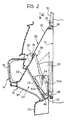
- the front bodywork part of a motor vehicle according to the invention is schematically indicated 10 and in correspondence therewith is fixed a radiator 12 of conventional type connected to the circuit for the coolant liquid of the vehicle engine, not shown in the drawings.
- the front bumper 14 of the vehicle extends horizontally in front of the front bodywork part 10 at the level of the lower zone of the radiator 12.
- the bumper 14 is of moulded plastics material and has a shape such as to allow it absorb the energy of minor frontal collisions of the vehicle resiliently.
- the bumper 14 has an upper part 16 projecting forwardly and defining the impact surface of the bumper, an intermediate part 18 inclined downwardly and being rentrant towards the front bodywork part 10, and a lower part 20 constituting a deflector or spoiler which is connected to the intermediate part 18.
- the portion of the intermediate part 18 facing the radiator 12 has a series of apertures 22 separated by transverse partitions 24 and surmounted by an inner inclined wall 23, for air for cooling the radiator 12.
- the rear section 28 includes an upper wall 30 inclined downwardly towards the bumper 14 and two downwardly tapering vertical side walls 32, which surround the outline of the radiator 12 with the interposition of a gasket 34 of soft material.
- the upper wall 30 has two upper rear fixing lugs 36 connected to the front bodywork part 10, for example by screws 38, and a flexible blade 40 at its front in sliding contact with the intermediate section 26.
- This section 26 includes an upper wall 42 which extends as an elongation of the upper wall 30 of the rear section 28 beneath the flexible blade 40, two side walls 44 disposed as elongation of the side walls 32 and inwardly thereof, and a base wall 46 which connects the base of the radiator 12 to the base of the part 18 of the bumper 14 having the apertures 22.
- the intermediate section 26 is connected to the structure of the vehicle by means of resilient rear tabs 48 projecting rearwardly from the base wall 46 and fixed to the front bodywork part 10 beneath the radiator 12.
- the intermediate section 26 is urged towards its normal position by a pair of pin-springs one of which is indicated 50 in the drawings, each of which has an arm 50a fixed to the front bodywork part 10 and/or to one of the side walls 32 of the rear section 28 and an arm 50b which bears resiliently against a front bearing flange 52 projecting laterally from the corresponding side wall 44 of the intermediate section 26.
- the radiator 12 is effectively cooled by the air flow which enters through the apertures 22 and is conveyed by the walls 23, 24, the intermediate section 26, and the rear section 28 against the front surface of the radiator itself.
- the resilient deformation of the bumper 14 causes the movement of the intermediate section 26 from its normal position to its retracted position against the reaction of the springs 50. Immediately the effect of the collision has ceased, the intermediate section 26 is returned to its initial position, automatically restoring the effectiveness of the conveyor 25.
- the two pin-springs 50 could be replaced by equivalent resilient systems, such as, for example, one or more flat springs applied to the upper wall 30 of the rear section 28 and acting against the intermediate section 26.
Landscapes
- Engineering & Computer Science (AREA)
- Chemical & Material Sciences (AREA)
- Combustion & Propulsion (AREA)
- Transportation (AREA)
- Mechanical Engineering (AREA)
- Cooling, Air Intake And Gas Exhaust, And Fuel Tank Arrangements In Propulsion Units (AREA)
Claims (4)
Applications Claiming Priority (2)
| Application Number | Priority Date | Filing Date | Title |
|---|---|---|---|
| IT6793083 | 1983-09-07 | ||
| IT67930/83A IT1193146B (it) | 1983-09-07 | 1983-09-07 | Autoveicolo avente un convogliatore dell aria di refrigerazione del radiatore per il liquido di raffreddamento del motore |
Publications (2)
| Publication Number | Publication Date |
|---|---|
| EP0134765A1 EP0134765A1 (fr) | 1985-03-20 |
| EP0134765B1 true EP0134765B1 (fr) | 1987-07-15 |
Family
ID=11306440
Family Applications (1)
| Application Number | Title | Priority Date | Filing Date |
|---|---|---|---|
| EP84830240A Expired EP0134765B1 (fr) | 1983-09-07 | 1984-08-21 | Véhicule moteur comportant une conduite pour l'air de refroidissement du radiateur dans lequel passe le fluide de refroidissement du moteur |
Country Status (5)
| Country | Link |
|---|---|
| US (1) | US4567955A (fr) |
| EP (1) | EP0134765B1 (fr) |
| DE (1) | DE3464723D1 (fr) |
| ES (1) | ES281384Y (fr) |
| IT (1) | IT1193146B (fr) |
Families Citing this family (9)
| Publication number | Priority date | Publication date | Assignee | Title |
|---|---|---|---|---|
| US4653788A (en) * | 1986-01-17 | 1987-03-31 | Fiat Auto S.P.A. | Front bumper for motor vehicles |
| US4902059A (en) * | 1988-09-19 | 1990-02-20 | Tritton Richard F | Vehicle bumper system for forming part of engine cooling assembly |
| DE4132570A1 (de) * | 1991-09-30 | 1993-04-08 | Bayerische Motoren Werke Ag | Kraftfahrzeug-vorderbau |
| US5460420A (en) * | 1994-11-09 | 1995-10-24 | Mccord Winn Textron | Compartmentized plastic bumper |
| DE19527442C2 (de) * | 1995-07-27 | 2002-04-11 | Behr Gmbh & Co | Luftleitkanal für eine Kühleinrichtung |
| DE19602186C1 (de) * | 1996-01-23 | 1997-05-22 | Porsche Ag | Kraftfahrzeug mit einer bugseitigen Kühleranordnung |
| AU2455401A (en) * | 1999-12-23 | 2001-07-03 | Textron Automotive Company Inc. | Air-intake management device |
| DE102005044286A1 (de) * | 2005-09-16 | 2007-04-05 | GM Global Technology Operations, Inc., Detroit | Kraftfahrzeug mit einem Spritzwasserbehälter |
| US20170299006A1 (en) * | 2016-04-15 | 2017-10-19 | GM Global Technology Operations LLC | Active airflow deflector for brake cooling |
Family Cites Families (9)
| Publication number | Priority date | Publication date | Assignee | Title |
|---|---|---|---|---|
| US2193229A (en) * | 1938-02-02 | 1940-03-12 | Gen Motors Corp | Bumper |
| US2260578A (en) * | 1940-01-06 | 1941-10-28 | Thomas E Murray | Automobile construction |
| US2329874A (en) * | 1941-11-21 | 1943-09-21 | Chrysler Corp | Combined bumper and grille |
| US2578068A (en) * | 1948-10-15 | 1951-12-11 | Clarence R Johnson | Combined bumper and grille |
| US2759755A (en) * | 1952-08-29 | 1956-08-21 | Clarence R Johnson | Combined bumper and grill |
| FR1518749A (fr) * | 1967-01-16 | 1968-03-29 | Citroen Sa Andre | Conduit de ventilation pour moteur de véhicule automobile |
| DE2727517A1 (de) * | 1977-06-18 | 1978-12-21 | Daimler Benz Ag | Kraftwagen mit vorderem stossfaenger |
| DE3010485C2 (de) * | 1980-03-19 | 1987-03-19 | Süddeutsche Kühlerfabrik Julius Fr. Behr GmbH & Co KG, 7000 Stuttgart | Kühleranordnung für Kraftfahrzeuge |
| GB2058921B (en) * | 1980-08-07 | 1983-06-29 | Walker Deutschland Gmbh | Airflow guide for the cooling fan of automobile engines |
-
1983
- 1983-09-07 IT IT67930/83A patent/IT1193146B/it active
-
1984
- 1984-08-21 EP EP84830240A patent/EP0134765B1/fr not_active Expired
- 1984-08-21 DE DE8484830240T patent/DE3464723D1/de not_active Expired
- 1984-08-30 US US06/645,995 patent/US4567955A/en not_active Expired - Fee Related
- 1984-09-06 ES ES1984281384U patent/ES281384Y/es not_active Expired
Also Published As
| Publication number | Publication date |
|---|---|
| ES281384Y (es) | 1986-05-01 |
| IT8367930A0 (it) | 1983-09-07 |
| US4567955A (en) | 1986-02-04 |
| EP0134765A1 (fr) | 1985-03-20 |
| ES281384U (es) | 1985-09-01 |
| DE3464723D1 (en) | 1987-08-20 |
| IT1193146B (it) | 1988-06-02 |
Similar Documents
| Publication | Publication Date | Title |
|---|---|---|
| JPH01156154A (ja) | 自動車用放熱器枠 | |
| US4379582A (en) | Device for improving aerodynamic and safety characteristics of automotive vehicles | |
| US5503444A (en) | Impact resistent flexible grille arrangement | |
| JP2605891B2 (ja) | バンパフェイシアの取付構造 | |
| EP1894792B1 (fr) | Structure de pare-chocs pour véhicules | |
| US5409288A (en) | Module carrier structure for vehicle front | |
| EP1232931B1 (fr) | Face avant pour véhicule automobile | |
| US4547013A (en) | Vehicle bug deflector | |
| US7488016B2 (en) | Vehicle front structure | |
| EP0055419B1 (fr) | Structure combinée de pare-chocs et de radiateur | |
| US7390038B2 (en) | Integrated bumper and upper fascia components of a motor vehicle | |
| JPH0319088B2 (fr) | ||
| EP0134765A1 (fr) | Véhicule moteur comportant une conduite pour l'air de refroidissement du radiateur dans lequel passe le fluide de refroidissement du moteur | |
| US4141426A (en) | Support assembly for radiators and air conditioning condensors | |
| US6070933A (en) | Automotive front lower structure | |
| US10131303B2 (en) | Bumper assemblies and vehicles with integrated air deflectors | |
| CN109421635B (zh) | 用于保险杠组件的保险杠盖保持器 | |
| US4877279A (en) | Stroking fascia for vehicle energy absorbing bumper systems | |
| GB2053822A (en) | Vehicle front end structure | |
| CN109421821B (zh) | 包括底盖加强构件的底盖组件 | |
| US10131305B2 (en) | Bumper assemblies and vehicles with integrated air deflectors | |
| JPH05170039A (ja) | 自動車の前部構造 | |
| EP0073317B1 (fr) | Caisson-traverse de tablier de véhicule à moteur | |
| JPH01109182A (ja) | 車体前部構造 | |
| JP3075043B2 (ja) | 自動車用熱交換器装置 |
Legal Events
| Date | Code | Title | Description |
|---|---|---|---|
| PUAI | Public reference made under article 153(3) epc to a published international application that has entered the european phase |
Free format text: ORIGINAL CODE: 0009012 |
|
| AK | Designated contracting states |
Designated state(s): DE FR GB SE |
|
| 17P | Request for examination filed |
Effective date: 19850130 |
|
| 17Q | First examination report despatched |
Effective date: 19860430 |
|
| GRAA | (expected) grant |
Free format text: ORIGINAL CODE: 0009210 |
|
| AK | Designated contracting states |
Kind code of ref document: B1 Designated state(s): DE FR GB SE |
|
| ET | Fr: translation filed | ||
| REF | Corresponds to: |
Ref document number: 3464723 Country of ref document: DE Date of ref document: 19870820 |
|
| PLBE | No opposition filed within time limit |
Free format text: ORIGINAL CODE: 0009261 |
|
| STAA | Information on the status of an ep patent application or granted ep patent |
Free format text: STATUS: NO OPPOSITION FILED WITHIN TIME LIMIT |
|
| 26N | No opposition filed | ||
| PGFP | Annual fee paid to national office [announced via postgrant information from national office to epo] |
Ref country code: GB Payment date: 19930715 Year of fee payment: 10 |
|
| PGFP | Annual fee paid to national office [announced via postgrant information from national office to epo] |
Ref country code: DE Payment date: 19930721 Year of fee payment: 10 |
|
| PGFP | Annual fee paid to national office [announced via postgrant information from national office to epo] |
Ref country code: SE Payment date: 19930730 Year of fee payment: 10 |
|
| PGFP | Annual fee paid to national office [announced via postgrant information from national office to epo] |
Ref country code: FR Payment date: 19930827 Year of fee payment: 10 |
|
| PG25 | Lapsed in a contracting state [announced via postgrant information from national office to epo] |
Ref country code: GB Effective date: 19940821 |
|
| PG25 | Lapsed in a contracting state [announced via postgrant information from national office to epo] |
Ref country code: SE Effective date: 19940822 |
|
| EAL | Se: european patent in force in sweden |
Ref document number: 84830240.2 |
|
| GBPC | Gb: european patent ceased through non-payment of renewal fee |
Effective date: 19940821 |
|
| PG25 | Lapsed in a contracting state [announced via postgrant information from national office to epo] |
Ref country code: FR Effective date: 19950428 |
|
| PG25 | Lapsed in a contracting state [announced via postgrant information from national office to epo] |
Ref country code: DE Effective date: 19950503 |
|
| EUG | Se: european patent has lapsed |
Ref document number: 84830240.2 |
|
| REG | Reference to a national code |
Ref country code: FR Ref legal event code: ST |