EP0134863A2 - Rail pour convoyeur à film d'air - Google Patents
Rail pour convoyeur à film d'air Download PDFInfo
- Publication number
- EP0134863A2 EP0134863A2 EP83306782A EP83306782A EP0134863A2 EP 0134863 A2 EP0134863 A2 EP 0134863A2 EP 83306782 A EP83306782 A EP 83306782A EP 83306782 A EP83306782 A EP 83306782A EP 0134863 A2 EP0134863 A2 EP 0134863A2
- Authority
- EP
- European Patent Office
- Prior art keywords
- rail
- bore
- load
- cannula
- nozzle
- Prior art date
- Legal status (The legal status is an assumption and is not a legal conclusion. Google has not performed a legal analysis and makes no representation as to the accuracy of the status listed.)
- Granted
Links
- 239000012530 fluid Substances 0.000 claims abstract description 52
- 239000000463 material Substances 0.000 claims abstract description 26
- 239000000945 filler Substances 0.000 claims abstract description 21
- 238000000034 method Methods 0.000 claims description 13
- 230000037361 pathway Effects 0.000 claims description 11
- 230000036961 partial effect Effects 0.000 claims description 7
- 238000005192 partition Methods 0.000 claims description 7
- 238000011084 recovery Methods 0.000 claims description 7
- 239000011888 foil Substances 0.000 claims description 4
- 229920006332 epoxy adhesive Polymers 0.000 claims description 3
- -1 polytetrafluoroethylene Polymers 0.000 claims description 3
- 230000006698 induction Effects 0.000 claims description 2
- 229920001343 polytetrafluoroethylene Polymers 0.000 claims description 2
- 239000004810 polytetrafluoroethylene Substances 0.000 claims description 2
- 238000005339 levitation Methods 0.000 abstract description 11
- 230000006872 improvement Effects 0.000 abstract description 6
- 230000002706 hydrostatic effect Effects 0.000 abstract description 4
- 239000010408 film Substances 0.000 description 12
- 230000005484 gravity Effects 0.000 description 10
- 230000008901 benefit Effects 0.000 description 8
- 230000000694 effects Effects 0.000 description 7
- 230000001965 increasing effect Effects 0.000 description 7
- 239000001913 cellulose Substances 0.000 description 5
- 229920002678 cellulose Polymers 0.000 description 5
- 238000010276 construction Methods 0.000 description 5
- 230000000875 corresponding effect Effects 0.000 description 5
- 230000002829 reductive effect Effects 0.000 description 5
- 238000004519 manufacturing process Methods 0.000 description 4
- 230000007246 mechanism Effects 0.000 description 4
- 230000007935 neutral effect Effects 0.000 description 4
- 230000009471 action Effects 0.000 description 3
- 239000004411 aluminium Substances 0.000 description 3
- 229910052782 aluminium Inorganic materials 0.000 description 3
- XAGFODPZIPBFFR-UHFFFAOYSA-N aluminium Chemical compound [Al] XAGFODPZIPBFFR-UHFFFAOYSA-N 0.000 description 3
- 239000006185 dispersion Substances 0.000 description 3
- 239000000123 paper Substances 0.000 description 3
- 238000012360 testing method Methods 0.000 description 3
- 230000007704 transition Effects 0.000 description 3
- XLYOFNOQVPJJNP-UHFFFAOYSA-N water Substances O XLYOFNOQVPJJNP-UHFFFAOYSA-N 0.000 description 3
- 230000004913 activation Effects 0.000 description 2
- 230000008859 change Effects 0.000 description 2
- 230000003247 decreasing effect Effects 0.000 description 2
- 238000005553 drilling Methods 0.000 description 2
- 230000003993 interaction Effects 0.000 description 2
- 238000002955 isolation Methods 0.000 description 2
- 238000005304 joining Methods 0.000 description 2
- 230000000670 limiting effect Effects 0.000 description 2
- 229910052751 metal Inorganic materials 0.000 description 2
- 239000002184 metal Substances 0.000 description 2
- 230000002250 progressing effect Effects 0.000 description 2
- 230000009467 reduction Effects 0.000 description 2
- 230000004044 response Effects 0.000 description 2
- 238000003860 storage Methods 0.000 description 2
- 239000010409 thin film Substances 0.000 description 2
- 238000004804 winding Methods 0.000 description 2
- 239000004593 Epoxy Substances 0.000 description 1
- 239000004698 Polyethylene Substances 0.000 description 1
- 230000002745 absorbent Effects 0.000 description 1
- 239000002250 absorbent Substances 0.000 description 1
- 238000010521 absorption reaction Methods 0.000 description 1
- 239000000853 adhesive Substances 0.000 description 1
- 230000001070 adhesive effect Effects 0.000 description 1
- 210000004712 air sac Anatomy 0.000 description 1
- 230000004075 alteration Effects 0.000 description 1
- 230000003190 augmentative effect Effects 0.000 description 1
- 230000015572 biosynthetic process Effects 0.000 description 1
- 238000006243 chemical reaction Methods 0.000 description 1
- 238000004140 cleaning Methods 0.000 description 1
- 239000002131 composite material Substances 0.000 description 1
- 230000001276 controlling effect Effects 0.000 description 1
- 229920001577 copolymer Polymers 0.000 description 1
- 230000009849 deactivation Effects 0.000 description 1
- 230000001934 delay Effects 0.000 description 1
- 238000013461 design Methods 0.000 description 1
- 238000001514 detection method Methods 0.000 description 1
- 238000009826 distribution Methods 0.000 description 1
- 230000009977 dual effect Effects 0.000 description 1
- 238000005516 engineering process Methods 0.000 description 1
- 230000002708 enhancing effect Effects 0.000 description 1
- 238000001125 extrusion Methods 0.000 description 1
- 239000000835 fiber Substances 0.000 description 1
- 229920002457 flexible plastic Polymers 0.000 description 1
- 238000007795 flow visualization technique Methods 0.000 description 1
- 239000002783 friction material Substances 0.000 description 1
- 230000006870 function Effects 0.000 description 1
- 239000003365 glass fiber Substances 0.000 description 1
- 238000009434 installation Methods 0.000 description 1
- 239000002655 kraft paper Substances 0.000 description 1
- 230000001050 lubricating effect Effects 0.000 description 1
- 230000013011 mating Effects 0.000 description 1
- 239000005300 metallic glass Substances 0.000 description 1
- 230000004048 modification Effects 0.000 description 1
- 238000012986 modification Methods 0.000 description 1
- 238000005457 optimization Methods 0.000 description 1
- 239000002245 particle Substances 0.000 description 1
- 239000004033 plastic Substances 0.000 description 1
- 229920003023 plastic Polymers 0.000 description 1
- 239000004014 plasticizer Substances 0.000 description 1
- 229920000573 polyethylene Polymers 0.000 description 1
- 239000004800 polyvinyl chloride Substances 0.000 description 1
- 238000012545 processing Methods 0.000 description 1
- 230000001737 promoting effect Effects 0.000 description 1
- 230000035485 pulse pressure Effects 0.000 description 1
- 238000005086 pumping Methods 0.000 description 1
- 230000002940 repellent Effects 0.000 description 1
- 239000005871 repellent Substances 0.000 description 1
- 238000011160 research Methods 0.000 description 1
- 230000000979 retarding effect Effects 0.000 description 1
- 238000000926 separation method Methods 0.000 description 1
- 229910001220 stainless steel Inorganic materials 0.000 description 1
- 239000010935 stainless steel Substances 0.000 description 1
- 239000000126 substance Substances 0.000 description 1
- LSNNMFCWUKXFEE-UHFFFAOYSA-L sulfite Chemical compound [O-]S([O-])=O LSNNMFCWUKXFEE-UHFFFAOYSA-L 0.000 description 1
- 238000011282 treatment Methods 0.000 description 1
- 230000003313 weakening effect Effects 0.000 description 1
- 238000003466 welding Methods 0.000 description 1
- 239000002023 wood Substances 0.000 description 1
Images


Classifications
-
- B—PERFORMING OPERATIONS; TRANSPORTING
- B65—CONVEYING; PACKING; STORING; HANDLING THIN OR FILAMENTARY MATERIAL
- B65G—TRANSPORT OR STORAGE DEVICES, e.g. CONVEYORS FOR LOADING OR TIPPING, SHOP CONVEYOR SYSTEMS OR PNEUMATIC TUBE CONVEYORS
- B65G51/00—Conveying articles through pipes or tubes by fluid flow or pressure; Conveying articles over a flat surface, e.g. the base of a trough, by jets located in the surface
- B65G51/02—Directly conveying the articles, e.g. slips, sheets, stockings, containers or workpieces, by flowing gases
- B65G51/03—Directly conveying the articles, e.g. slips, sheets, stockings, containers or workpieces, by flowing gases over a flat surface or in troughs
Definitions
- the present invention relates in general to improved hydrostatic bearing levitation systems; that is, to systems using fluid pressure to support and guide heavy loads as they move along a track system using rails.
- the nozzles are angled so that their net effect is a fluid film wedge reaction on the load supporting member which directs it in the desired direction and which also tends to displace the load and the supporting film wedge towards one side of the rail.
- the principles outlined in very basic terms above are applicable to material handling systems, as in single-rail systems operating as an air- conveyor for trans-porting cyclindrical objects such as paper rolls, or in twin-rail track systems for transporting pallets from a loading or unloading dock into or out of a transport trailer, or holding and feeding pallets in and through a gravity flow racking system, and they are also applicable to so-called "people-movers" such as inter-or intra-urban transportation systems.
- systems such as those described in the aforementioned patents may be broadly characterized as compliant hydrostatic bearing levitation systems for moving heavy loads along supporting rails.
- the systems utilize "shoes" of cellulose or like material wound tightly about a collapsible core and enclosed by a deformable but stiff cover of flexible plastic or metal, which shoes exhibit low friction properties when in juxtaposition with a trough-like section of support rail, curved at a radius only slightly greater than that of the shoe.
- the shoes move freely in the rail(s) when small nozzles in the curved rail surface exhaust fluid therethrough under pressure in particular patterns to create fluid cavity cells and fluid lubricated seal areas under the shoes, the shoes being guided by the fluid film wedge formed with the curved contour of the rail section.
- the invention provides an improved rail for use in mono- or multi-rail fluid-pressure supported article transportation systems comprising a shallowly transversely concave upper wall member, a pair of generally vertical, longitudinally extending side walls, each inset from a corresponding edge of said upper wall member, a generally planar lower wall member extending transversely outwardly beyond each side wall, partition wall means extending between said upper and lower wall members so as to define at least two longitudinally extending ports within said rail, a plurality of nozzles communicating through the upper wall member with said ports, the nozzles being longitudinally aligned in groups such that there is a space between longitudinally adjacent groups for each of said ports and such that the groups associated with one port are longitudinally staggered with respect to the groups associated with the other of said ports, each nozzle being angled with respect to a longitudinally extending plane which is tangent to the outer curved surface of the upper wall member where the axis of the nozzle intersects the outer surface.
- the improved rail reflects optimization of most, if not all, of the operating areas enumerated above.
- the improved rail may be extruded inexpensively from a commercial grade of aluminium; it can be quickly and accurately joined end-to-end to an adjacent rail; its nozzle size, configuration, layout and operation can promote efficiency; and it can be adaptable to many different configurations depending on the ultimate usage to which it is to applied.
- the rail could be fabricated from a rolled or extruded from a copolymer such as polyvinylchloride (PVC) or reinforced polyethylene, the greatest success has been achieved with a rail extruded from commercial aluminium stock.
- the rail includes internal vertical partitions between the upper and lower walls dividing the interior into longitudinally extending ports or passageways which carry the pressurized fluid and obviate any need for separate headers or storage reservoirs for the fluid supply.
- a very desirable rail configuration includes three internal partitions which, along with the side walls of the rail, define four parallel longitudinal ports or passageways in each rail; typically the two innermost ports would be used.
- Such a rail in combination with a unique nozzle arrangement and control system, makes the rail of this invention particularly suited for controlled product flow in gravity sloped storage racks of the first-in first-out type.
- each group there could be overlap between the staggered groups of nozzles in the two rows.
- the length of each group would be related to the length of whatever load, such as a pallet, was to be levitated in the track system or to the desired length of travel of a pallet or a group of pallets. In most cases the length of the load to be carried, or at least the total length of the shoes supporting the load, would be approximately related to the length of each group of nozzles depending on the movement or interaction with the rail required.
- staggered groups of nozzles permits a load supported by sectionalized lengths of rail to be indexed, in a controlled manner, on application of pulses of fluid, forwardly by manual or automatic means, or on a sloped gravity flow track a set distance corresponding to a group length by applying fluid pressure alternately to the two ports supplying the nozzles.
- the load would advance a distance corres-ponding to one group only, where the open distance between loads allows.
- the other port would be pressurized so that the next group of nozzles, residing in a staggered group communicating with the other port, would levitate the load for advancement.
- both ports are pressurized simultaneously, the load will be able to move continuously along the track, being levitated alternately as it moves by nozzles supplied by one port and then by nozzles supplied by the other port. If only one port is pressurized the load travel is limited to the length of a nozzle group as there is a space which has no levitation fluid film between the actuated group of nozzles and the next group communicating with the pressurized port.
- Overlap at the ends of alternate staggered groups permits smooth transition from group to group and also permits special movement situations.
- the spacing between the groups of the longer (outer) port could be increased, or decreased, if desired, to cater to the sideways forces due to centrifugal or gravity effects encountered with banked tracks.
- the spacing between groups could be reduced to provide greater overlap between the staggered groups.
- spacings could be increased to reduce overlap in declining-elevation tracks.
- Simple OR or AND/OR control valves can be used to control the flow of fluid to pressurize a selected one, or both, of the ports providing pressurized fluid to the nozzle groups.
- a four-way spool valve having a neutral "off" position a single spool operator ensures that only one or the other of the nozzle groups can operate, automatically providing an interlock feature.
- the construction of the nozzle can be enhanced if, instead of drilling by mechanical, electric discharge or laser techniques a bore of nozzle diameter extending through the curved upper wall, a bore of larger diameter is provided and that bore is filled with a cannula of the desired small nozzle diameter, the outer wall of the cannula forming a tight, suitably sealed fit with the bore provided in the rail upper wall.
- the invention provides a method of constructing a nozzle for the passage of a pressurized fluid from a plenum area, through a wall of said plenum area, to a reception area, comprising the steps of: creating a bore extending through said wall at a desired angle, said bore having a diameter greater than the diameter of said nozzle; inserting a cannula into said bore, said cannula having an outer diameter approximately equal to that of said bore and an inner diameter equal to said nozzle diameter; and fixing said cannula within said bore.
- Such a method may find wider application, but in manufacturing a rail as set out in the last preceding paragraph but nine the cannula, which may desirably be a hypodermic needle, may be bonded in the rail bore, as by an epoxy adhesive, if necessary.
- the cannula which may desirably be a hypodermic needle
- a portion thereof may extend into the port beyond the inner surface of the upper wall to provide desirable lower power flow characteristics through the nozzle.
- Fluid power characteristics may also be improved by using an interrupted cannula which defines one or more flow turbulence cavities between the sections thereof.
- the outermost end of the cannula may be inset below the outer surface of the upper wall surface so that a portion of the original larger bore is exposed to the rail surface, creating an enlarged nozzle portion adjacent the upper surface which acts as a resonant, turbulence or distribution chamber and, in fact, aids in enhancing the flow losses of the fluid entry to the shoe/rail interface cavity and/or the desirable dither effect of the shoe cover.
- a hypodermic needle is usually formed from stainless steel and since the rail is usually extruded aluminium, it can be seen that the cannula will likely have a smoother surface than a straight drilled nozzle in the rail and that it will likely have better wear properties for extreme nozzle fluid velocities.
- the entry portion of the cannula can be provided with special flow limiting features to provide additional nozzle power reductions. The features include an angled cut-off, sharpening and/or turbulence grooving treatments.
- the invention provides a load supporting means for positioning between a load and a load supporting surface, said means being capable of supporting said load and of substantially isolating said load from forces influencing the position of said surface, said means comprising a generally tubular outer member formed of a flexible partly deformable material capable of deformation under load and at least partial recovery under load removal, and, internally of said outer member, an annular deformable core extending generally axially of said outer member creating an annular cavity between said core and said member, said cavity being filled by a web of cellulosic material wound tightly on said core, said cellulosic material being formed from a pulp containing a high percentage of groundwood and having a negligible degree of crepe.
- the invention provides a load supporting means for positioning between a load and a load supporting surface, said means being capable of supporting said load and of substantially isolating said load from forces influencing the position of said surface, said means comprising a generally tubular outer member formed of a flexible partly deformable material capable of deformation under load and at least partial recovery under load removal, and, internally of said member, a plurality of longitudinally adjacent inflatable bladder members for peripherally prestressing said outer member.
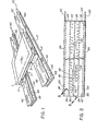
- FIG. 1 of the drawings is intended to illustrate a basic transport system utilizing the rail section of the present invention.
- a system includes a load L, shown in this figure as being on a pallet P, supported by a pair of spaced apart members (shoes) S, and a track made up of a pair of rails R.
- a load L shown in this figure as being on a pallet P, supported by a pair of spaced apart members (shoes) S, and a track made up of a pair of rails R.
- the load could take any one of a number of different configurations ranging from individual cylinders of product or wound paper, through to pallets (as shown), and to vehicular modules for freight and/or people moving.
- the illustrated pallet is intended to be representative of all loads and should not be construed as a limitation of the invention or of systems using the invention.
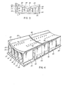
- the rail R is shown in end view in Figure 3 wherein it is seen to have a concave upper wall 20, the upper surface 22 of which has a radius of curvature slightly greater than that of the shoe S in its operative (compressed) condition.
- a pair of side walls 24 are provided, inset from the longitudinal edges of the upper wall and extending from the upper wall to a generally planar bottom wall 26, the longitudinal edges of which extend or project laterally outwardly of the adjacent side wall 24.
- At least one partition 28 extends between the upper and lower walls to create a longitudinally extending port on each side. In the preferred embodiment of Figure 3, three partitions 28, 30, 32 are used, creating with the side walls four longitudinally extending ports or passageways 34, 36, 38 and 40.
- the basic principles on which loads may be carried by rails of the present invention necessitates the provision of a plurality of nozzles extending from a pressurizable plenum within the rail, through the upper wall, and exiting at the curved upper surface of the rail.
- the nozzles should be assymetri- cally disposed with respect to the longitudinal axis of the rail and they should be angularly disposed with respect to at least three orthogonal planes, one of which is tangent to the upper surface of the rail at the intersection of the nozzle axis with the surface.
- the basic patent taught two rows of nozzles disposed as defined above and extending along the full length of the rail with a uniform spacing between adjacent nozzles.
- Rails in accordance with the basic patent operate very well but they do have certain drawbacks.
- long rails of the basic patent require more energy to provide the necessary fluid flows than may be desirable, especially with single pallet loads.
- the rails of the present invention represent an improvement over rails of the basic patent and provide some power and control features lacking in the original rails.
- the other major differences between the original rails and those of the present invention lie in the use of a single row of nozzles, in the disposition of the nozzles and in the configuration thereof, including the method of forming the nozzles in the upper wall of the rail.
- the rail is provided with groups 42, 44 of nozzles 46.
- Groups 42 are longitudinally aligned with each other along the rail and adjacent groups are separated by a space 48.
- the nozzles 46 of groups 42 communicate with and are associated with port 36, one of the two innermost ports of the rail.
- Groups 44 are also longitudinally aligned with each other along the rail and adjacent groups are separated by a space 50.
- the nozzles 46 of groups 44 communicate with and are associated with port 38, the other of the two innermost ports of the rail.
- each group 44 lies laterally opposite a space 48 and each group 42 lies laterally opposite a space 50.
- the number and positioning of groups 42 and 44 are such that when rails are joined end-to-end there will be a smooth transition from rail to rail with no interruption of the longitudinal nozzle pattern, whereby a load progressing along a track made up of a plurality of end-joined rails will not be materially aware of the joints between end-adjacent rails.
- a space 48 will be equal in length to a space 50 and the length of each group 42, 44 of nozzles will usually be longer than the length of the shoe used for load support.
- the end few nozzles of the staggered adjacent groups may overlap longitudinally of the rail.
- Variations in the spacings 48, 50 may be desirable for particular track requirements. For example, if the direction of load movement necessitates a positive elevation change the spacings 48, 50 might be reduced in length in comparison to what they might be for horizontal track portions, perhaps increasing the degree of overlap between the staggered groups of nozzles, to ensure minimum propulsion powers or to minimize whatever deceleration of the load might occur. For negative elevation changes, the spacings 48, 50 might be inceased somewhat.
- the spacing between groups of nozzles along the "outside” and between groups of nozzles along the "inside” of the curve might be decreased, thereby providing improved support by way of increased volumes or pressures of pressurized fluids offsetting the effects of centrifugal or gravity forces acting on the load as it travels along the curved track and the slight misalignment of the shoe in the curved rails.
- a slightly tipped or banked track might be provided with only one row of nozzles communicating with the outside one of the innermost ports.
- the spacing between the outside groups of nozzles would be equal to the spacing between adjacent nozzles of the groups while the spacing between the inside groups of nozzles would . be equal to the length of the curved rail section, thereby eliminating the inside groups of nozzles.
- both rows of nozzle groups could have their inter-group spacings reduced and both supply ports pressurized so that both rows of nozzles are simultaneously energized for greater load support.
- each nozzle should be disposed so that they were angled with respect to three orthogonal planes, one of which is tangent to the surface of the rail at the intersection of the nozzle axis with that surface. That disposition gave each nozzle a longitudinal component, preferably in, but not restricted to, the direction of load movement along the rail.
- the cavities 56 are in a dynamic state, continuously being created adjacent the front of the shoe and progressing to the rear as the shoe advances.
- the flow velocities and cavity depth in theory are in a dynamically unbalanced state and, surprisingly, that is an advantage with this invention. This unbalance creates a desirable dynamic "dither" of the shoe cover, as supported by the filler, at the seal area which tends to reduce “stiction” and improves the propagation of the air film and the ease with which a load can progress along a rail.
- the orientation of the nozzles is concerned it is considered to be very desirable for them to be at a transverse angle for reduced nozzle exit losses.
- it is not deemed absolutely necessary to provide a longitudinal component to the jet issuing from the nozzle it is preferable to angle the nozzles at about 45° to the longitudinal axis to provide more efficient levitation and a movement component along the track.
- the nozzle need be angled only with respect to a longitudinally extending plane which is tangent to the rail surface at the intersection thereof with the nozzle axis.
- the angled nozzle jet has been found to be more efficient, providing more levitation power, than a radially directed nozzle jet.
- the angled jet produces skin flutter with less losses at the outlet, where fluid is introduced to the shoe/rail interface. Also an angled jet having an angled inlet within the rail supply port exhibits reduced open track air losses. Thus, the angled nozzle provides the least resistance to air flow under the shoe on the rail but also provides the most inlet resistance for least flow from uncovered nozzles to the atmosphere.
- Figure 5 shows several of the features discussed above and also shows a desirable nozzle construction which reduces greatly the cost of manufacture.
- the nozzle 46 has an axis A which is at an angle a to a plane P l , which, in turn, is tangent to the rail surface 22 at the intersection, the nozzle 46 being directed transversely of the rail itself.
- the angle a is in the region of 20° although an optimum angle might have to be developed experimentally for any particular rail/load application.
- the nozzle is constructed by simply boring a hole of the desired diameter through the rail upper wall or, preferably, by boring a hole 62, larger than the desired nozzle diameter, through the rail upper wall 20 at the angle ⁇ . Then a cannula 64 having an outer diameter approximately equal to the diameter of the hole 62 is inserted into the hole so that a major portion 66 thereof projects into the port 36.
- the cannula 64 has an inner bore 68 of the desired nozzle size.
- the upper end face of the cannula is angled as at 70 so as to be generally coplanar with the rail outer surface 22 at the periphery of the bore 62.
- the inner end face of the cannula is preferably steeply angled or bevelled as at 72 or otherwise modified with a rough or notched surface so as to provide a high loss inlet which, in turn, reduces the flow from uncovered nozzles to the atmosphere. This avoids the need to use very small nozzle bores which may be prone to clogging.
- the bevel angle a is suggested to be in the range of 10 to 20° to the nozzle axis but, again, circumstances might dictate an angle outside the suggested range.
- the cannula 64 could be a commercially-available hypodermic needle modified so as to have the desired end face configurations.
- the needle could be secured in the hole 62 by an interference fit therewith or it could be bonded to the rail by a suitable adhesive, such as an epoxy adhesive.
- Figure 6 shows a slightly different nozzle configuration wherein the outer face is normal to nozzle axis A and is recessed below the rail outer surface 22. This creates an enlarged nozzle chamber portion 74 adjacent the rail surface 22 of the diameter of the hole 62. The enlarged chamber portion reduces exit losses of the fluid flow into the shoe cavity and acts as a resonant chamber for the nozzle jet, optimizing the nozzle advantages.
- the angled nozzle tends to be self-cleaning as the jet velocity is able to act on dirt collected in the outlet when no fluid is passing therethrough. This can be augmented if the outlet of the nozzle is radiused so as to increase outlet efficiencies.
- the projected tube or cannula entry portion 66 also serves to reduce dirt or moisture entry into the nozzle from the supply port (36,38) as it operates in a manner similar to a dry pipe or a clarifier system, causing the fluid to sharply change direction before entering the cannula bore 68.
- FIG. 6a Alternative nozzle configurations are shown in Figure 6a and in Figures 6b and 6c, both being variations on the configuration of Figure 6.
- the cannula 64 is inserted into the bore 62 as in the previous embodiments, but it is inserted deeper into the bore 62 than before.
- a second length of cannula 76 is inserted into the bore 62 and is secured therein so that it is spaced from the upper end face of the cannula 64 by a gap 78.
- the end of bore 62 adjacent the rail upper surface 22 is not filled and thus acts as a resonant chamber 74.
- the gap 78 between the portions 64, 76 of this "interrupted" cannula acts as a turbulence producing cavity, improving the fluid-flow characteristics.
- Figures 6b and 6c show another nozzle configuration which is a variation on the embodiment of Figure 6.
- a circular cutter head such as 80 is fed towards the upper surface 22 of the rail along an axis normal to the nozzle axis A.
- the axis of the cutter head 80 could be offset laterally from the nozzle axis so that the resulting circular cavity 82 produced in the rail upper surface is also offset from the nozzle axis A.
- the nozzle does not meet'the cavity 82 along a radius thereof.
- the jet exits the nozzle it will be forced, by the side wall of the cavity 82, into a spiral, swirling flow pattern and will thus exit from the nozzle in a better dispersion pattern, improving the levitation efficiency.
- FIGS 1, 3 and 4 illustrate the connection system of the present invention.
- the side walls 24 are inset from the longitudinal edges of the upper and lower walls 20 and 26, respectively. This creates a recess 84 along the outside of each side wall of the rail.
- a spline member 86 is positioned in each of the recesses 84 and is secured to the rail in any suitable manner, as by bolts or welding.
- the cross-section of the spline member 86 generally conforms to that of the recess 84 ( Figure 3) so that the spline member 86 has a snug fit in the recess 84 and so that the spline member preferably does not extend laterally outwardly of the recess.
- the spline member 86 is inset from one end of the rail section by a distance 88.
- a second spline member 90 is secured in each recess 84 at the other end of the rail, the spline member 90 having the same cross-sectional configuration as the spline member 86. As can be seen in Figures 1 and 4, a portion 92 of the spline member 90 projects or extends beyond the adjacent end face of the rail, the length of the extension 92 being no less than that of the inset distance 88 and preferably slightly greater than that distance. Both spline members 86 and 90 are provided with longitudinally aligned and extending bores 94 which can receive bolts 96.
- the extensions 92 of the spline members 90 of one rail are slid longitudinally into the corresponding inset recess portion 88 of the adjacent rails until the extensions 92 of the one rail butt against the spline members 86 of the adjacent rail.
- a resilient compressible gasket member is preferably positioned in the gap 98 between the rails, the gasket having essentially the same cross-section as the rail.
- the bolts 96 are inserted through the bores 94 of the abutting spline members; nuts (not shown) are secured to the free ends of the bolts; and the connection is tightened until the end face of each spline member 90 is securely and tightly abutting the end face of its adjacent spline member 86.
- This tightening action compresses the gasket in the gap 98 and seals the gap against intrusion by moisture or dirt and against leakage from the pressurized ports.
- the gasket is dimensioned so that after it has been compressed between the end faces of the rails its uppermost edge will not project above the rail upper surface 22 and its inner edges will not project into any of the pressurized rail ports:_ End plates can be affixed to the rails with screws and a gasket to form rail end seals or, in conjunction with a loosely tightened splice bolt arrangement, can provide a slide type expansion joint while maintaining rail alignment. External flexible hoses would be used to provide continuity of fluid pressure from port to port as required.
- Figure 9 shows a typical racking structure 100 made up of vertical front and rear members 102, 104 and horizontal front, rear and side members 106, 108 and 110.
- the various vertical and horizontal frame members define pathways leading from the rear of the racking structure to the front, usually at a slight downward slope.
- a typical pathway has been heavily outlined in Figure 9.
- Figure 10 shows the pathway of Figure 9 as it might appear with rails of the present invention utilized therein.
- the rails 112, 114 are joined end-to-end to form a two-rail track system 115, supported by the horizontal frame members 106, 108, the rails being spaced apart an appropriate horizontal distance to accept the longitudinally extending shoes supporting a load-carrying-pallet (see Figure 1).
- the rails slope downwardly from member 108 towards member 106 at an angle of about 1.5 0 to the horizontal so that, when in a fluid-levitated, supported condition, a pallet will tend to move downwardly along the track under the influence of gravity. In this way a separate movement- imparting power source is not required.
- the illustrated racking system is of the first-in first-out variety, in that a load introduced into the racking at the "high” or rear side will be taken out at the "low” or front side, the loads automatically accumulating at the low side.
- Such a control system should preferably operate automatically to advance loads through a pathway in response to the introduction of a new load into the pathway and it should also be manually operable so that an operator can selectively advance loads in a particular pathway.
- the control system should be economic to operate so that it does not pressurize any more than the minimum length of the rails to achieve the desired load movement.
- the control system In its automatic mode, the control system should detect the presence of a load by detecting the pallet, the shoe, a lift fork, or any other element intimately associated with a new load, and in response to such detection, it should pressurize the rail ports to activate the group of nozzles at the high end of the track so that the load, when introduced therein, is supported by the fluid film generated by the fluid issuing from that group of nozzles.
- the load will advance over the initial group of nozzles under the influence of gravity until it encounters a non-pressurized space at which point it will come to halt.
- the control system can be programmed in accordance with the nozzle layout on the track to then advance the load as desired.
- the control system might permit the first load to advance two load lengths before it is stopped, so that when another load is introduced into the pathway there will be a one-load length empty buffer space between the two loads, the first load advancing as the second load advances.
- the unload end of the rails When the unload end of the rails is reached, the spaced- apart loads will close up ranks until the pathway is filled.
- the control system detects the load removal and can be programmed to provide a safety delay to prevent the loads behind the load being removed from advancing until the unload position has been vacated. Thereafter, the control system alternately energizes nozzle groups to index the accumulated, loads in a controlled manner into the vacated space(s).
- One particular advantage of using a rail according to the present invention in a racking environment is that the staggered nozzle groups prevent any runaway loads, a problem that exists with roller conveyor racking systems unless special retarding devices are utilized and matched to the particular load weight involved or would exist with air levitation systems which are continuously pressurized over the entire length thereof unless the fluid is pulsed in a programmed sequence or is controlled by cascade type valves.
- the system is designed to take advantage of the staggered nozzle groups since, as a load comes to a non-pressurized group, it will halt its movement along the rail, even though the other nozzle groups, staggered with respect to the non-pressurized group, be pressurized. This is a significant safety advantage as it provides controlled movement of a load at all times.
- control system is, in essence, a pneumatic or pneumo-electric circuit including various valves, timers, gates, actuators and switches which can be assembled by any competent technician to achieve the desired programmed movement pattern.
- FIG. 11 Most components for the circuitry are off-the- shelf items although in at least one instance the unique rail configuration permits a very compact and efficient assembly, as particularly shown in Figure 11.
- a rail 116 is illustrated, having ports W, X, Y and Z extending lengthwise thereof.
- a companion rail 118 is also illustrated, having corresponding ports W 1 , X 1 , Y and Z 1 .
- Rail 118 is shown as having an end cover 120 thereon, the end cover and gasket having been secured to the rail in any suitable manner. The equivalent end cover has been omitted from the rail 116 for the sake of clarity.
- Each port W, X, Y and Z is shown as having an aperture 122 extending through the bottom wall thereof, each aperture preferably being in the form of a round-ended slot.
- a modular valve and control block 124 may be bolted to the underside of the rail by way of bolts or machine screws 126 passing through suitable holes in the block 124 and the rail bottom wall.
- a gasket 128 may be compressed between the underside of the rail bottom wall and the top surface of the block 124 to seal the connection between the block and the rail.
- Gasket 128 has through-apertures 130 which mate with the apertures 122 in the rail and with apertures 132 in the block 124. "0"-ring type seals may be used in place of the gasket 128.
- Block 124 is an assembly of several modules each performing its own separate function.
- the block 124 includes a four-way, three position pilot operated spool valve 134, the details of which do not form a part of the present invention. In one position the spool valve will pneumatically connect port W with port X and in another position it will pneumatically connect port Z with port Y. The third position of the valve spool is a neutral position in which there are no pneumatic interport connections.
- the block 124 also includes a number (six shown) of pneumatic circuit devices 136, which devices may be gates, timers, delays, or other logic control devices. Several of the devices may be adjustable so that desired operating conditions or criteria can be met.
- the circuitry for the logic devices may be housed in a manifold sub-base 138 through which the apertures 132 and the mounting screw holes pass. The circuitry contained within the sub-base 138 will depend on the arrangement of the logic devices 136.
- a normally-closed micro-switch 142 is located at the "load" end of the rail 116 and is pneumatically connected to port Z by conduit 144.
- Conduit 146 leads to a normally-open microswitch 148 which is downstream of switch 142 and which is also connected to port Z, by a conduit 150.
- a conduit 152 connects the switch 148 to the valve/logic block 124.
- Another conduit 154 connects switch 142 to switch 148 and then to the block 124, the connections between the conduit 154 and the switches being by way of variable flow control valves 156 which valves provide a safety delay.
- Appropriate sensors, such as spring-loaded whiskers 158, 160 are used to activate switches 142, 148, respectively, when contacted by a load moving along the rail 116.
- valve 134 might return to its neutral position whereby neither port X or Y is pressurized and the lack of levitation fluid will bring the load to a halt through contact with the rail.
- the valve 134 might move to its opposite position wherein the other of the supply ports W or Z is connected to its adjacent port X or Y and the other groups of nozzles are energized, whereby the load will continue to move along the rail.
- Any number of switches may be positioned along the rail, or any programming controlled by the switches may be used, so as to control movement of a load therealong.
- a significant advantage in power savings may be achieved with a modular control system as described above.
- a pair of rails are laid parallel to form a track, as seen in Figure 11, it is only necessary to pressurize one of the rails and to mount a control block 124 and appropriate switches to that rail since conduits 162, 164 can be con- . nected between the four way valve 134 and directly to the two innermost ports X I and Y, of the adjacent rail.
- Pressurized fluid for the ports X and X l thus comes from the supply port W of rail 116 and pressurized fluid for the ports Y and Y 1 comes from the supply port Z of rail 116. Since the rails 116 and 118 would be identically constructed the unused apertures 122 in the ports W l and Z I of rail 118 could be blocked off and those ports could be used as additional pressurized surge reservoirs or, in the warehouse situation, they could be used as headers for an in-rack water sprinkler system.
- each such module could be controlled by a system as described in Figure 11 and each rail module could, in turn, include appropriate control valving so that as a load approached the end of one module the additional valving would be activated so as to pressurize the nozzle ports of the next rail module before the load meets that module, thereby ensuring smooth movement of the load along the rail while avoiding the necessity of continuously pressurizing the nozzle ports along the entire length of the rail.
- the foregoing has described the main features and options of a rail according to the present invention, and of a track system using such a rail.
- the rail has been described as using a system of nozzles in two parallel rows, the nozzles of each row being arranged in aligned groups with a space between groups of a row and with the groups of one row being staggered with respect to the groups of the other row.
- the groups are of uniform length, as are the spaces, although the spaces need not be of the same length as the nozzle groups, as when there is overlap between the end few nozzles of adjacent staggered groups.
- nuzzle arrangements One particular variation in nuzzle arrangements has been previously described, that being for a curve wherein the spacing between the groups of one row is shortened until that row, in essence, becomes a row of continuous nozzles with each nozzle being spaced from the next nozzle in the row by the same amount. Both rows may be arranged in this manner or only one row, preferably the outer row of a curved rail, may be so arranged. In special banked cases, the space between adjacent groups of the other row is so great that no nozzles appear in that row in that portion of the rail.
- nozzle groups may be utilized.
- very long nozzle groups may be used, along with shorter lengths, to achieve movement of a load for a considerable period before the load need stop.
- staggered nozzle groups might be used for the first 10 feet of a rail, allowing the load to index slowly therealong as the nozzle groups are alternately energized.
- the next 25 feet of rail might use a single group of nozzles to provide continuous movement of a load therealong and the last 20 feet might again use staggered shorter nozzle groups to achieve slower indexing movement of the load.
- the nozzle group arrangements may be varied to achieve the desired load movement along the rail.
- Yet another nozzle configuration may be utilized, especially in areas where the rail will be subjected to extreme dirt or heavy moisture conditions (fogging).
- Rails used in such environments could use double rows of nozzles operating on the opposite side of the rail centerline and directed towards the converging area of the shoe cavity at the seal area between the rail and the shoe. The jets issuing therefrom create additional dynamic action to overcome the additional frictional shear forces.
- the shoe was described as including as outer cover which is deformable under load and is capable of at least partial recovery under toad removal, a central collapsible core, and a filler between the core and the cover, the filler also being deformable under load and being capable of at least partial recovery under load removal.
- a particularly efficient filler and core combination was found to be a specially wound roll of cellulosic extendable paper product.
- the cellulosic product should be wound from a sheet that has its finish controlled precisely (very little variation) by using virgin pulps with a high percentage of groundwood. Groundwood appears to exhibit the original integrity of wood without the undesirable weakening of the fibre through chemical or thermal pulp processing inherent with sulphite or kraft pulps. Secondary or reclaimed fibres should be avoided. There is no need for an absorbent sheet and abosorbency should be avoided. Indeed, it is desirable to use some of the newly available water repellent means.
- the web should have high strength in tension, being wound as tightly as possible on the core to provide high density and hardness with maximum viscoelastic effect in terms of memory recovery of the fibres.
- the core on which the web is wound should be strong to maintain the tension and alignment of the cellulose log, the log being the resulting roll after winding and having a desired length approximately equal to the length of the shoe.
- the core must also be able to collapse, as taught in the prior patent since such collapse (after final construction of the shoe and the first imposition of a load thereon) provides and maintains the necessary softer shoe footprint center portion (cavity 56, Figure 8) while providing the harder outside two seal areas 58, 60 with graded degrees of variation throughout.
- the shoe should be square end sealed with flexible diaphragms which are welded or heat sealed in place to both the cellulose end of the log and the cover. Such an end seal will waterproof the interior of the shoe while permitting the necessary flexibility thereof.
- the bottom edge of the cover, at each end, may be heat formed with a slight upwards curvature to limit catching on projections.
- the ends of the shoe can be formed as a "pocket" to collect debris, dirt particles, etc., which are picked up from the track.
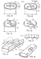
- the embodiment of Figure 12 is attractive if the shoe is to be used in conjunction with a linear induction motor (LIM) with the primary coil embedded in the rail.
- the outer cover 174 could be metallic or an amorphous metal foil and could act as the secondary for the LIM.
- the shoe/rail system is conducive to LIM's due to the small air gap between the shoe and the rail, making the LIM very efficient.
- An alternative secondary would be achieved by interleaving amorphorous metal sheets in the outer plies of the filler.
- the optimum length of a shoe for material handling and other application is about 48 inches.
- Such a long shoe makes it necessary for any curves to have a large radius of curvature if the shoe is to remain in the upper profile of the rail and be levitated by supporting fluid. It is desirable to reduce the length of the shoe to about 24 inches, in which case shoes would have to be mounted in tandem to achieve the design load-handling capabilities.
- Such shoes should also be articulated somewhat to accommodate rail irregularities and smaller radii.
- Figure 16 shows one means of articulating a shoe so as to achieve limited pitch and yaw movement.
- a short shoe 190 is affixed to a longitudinally extending U-shaped bracket 192 having a central cut-out and platform section 194.
- the short shoes 196 further isolate the load from the rail, provide additional springing and isolation, and permit limited relative pitch and yaw of the shoe 190 with respect to the load 198, while limiting roll.
- Figure 17 shows another shoe embodiment wherein the shoe 200 has a plurality of transverse cuts 202 extending therethrough, the cuts being only in the upper half of the shoe.
- the interior of the shoe at the cuts would have to be waterproofed as by applying flexible tape over each cut.
- Such a shoe would exhibit increased flexibility for curves or elevation changes while maintaining proper footprint length requirements.
Landscapes
- Engineering & Computer Science (AREA)
- Fluid Mechanics (AREA)
- Mechanical Engineering (AREA)
- Physics & Mathematics (AREA)
- Drying Of Solid Materials (AREA)
- Compressor (AREA)
- Intermediate Stations On Conveyors (AREA)
- Magnetic Bearings And Hydrostatic Bearings (AREA)
- Coating Apparatus (AREA)
- Supports For Pipes And Cables (AREA)
- Self-Closing Valves And Venting Or Aerating Valves (AREA)
- Structure Of Belt Conveyors (AREA)
- Branching, Merging, And Special Transfer Between Conveyors (AREA)
- Bearings For Parts Moving Linearly (AREA)
- Pallets (AREA)
- Warehouses Or Storage Devices (AREA)
- Non-Mechanical Conveyors (AREA)
- Spray Control Apparatus (AREA)
- Automobile Manufacture Line, Endless Track Vehicle, Trailer (AREA)
- Forklifts And Lifting Vehicles (AREA)
Priority Applications (1)
| Application Number | Priority Date | Filing Date | Title |
|---|---|---|---|
| AT83306782T ATE43323T1 (de) | 1983-06-30 | 1983-11-08 | Tragschiene fuer luftfilmfoerderer. |
Applications Claiming Priority (2)
| Application Number | Priority Date | Filing Date | Title |
|---|---|---|---|
| CA000431658A CA1167797A (fr) | 1983-06-30 | 1983-06-30 | Dispositif de transport par sustentation pneumatique |
| CA431658 | 1983-06-30 |
Related Child Applications (2)
| Application Number | Title | Priority Date | Filing Date |
|---|---|---|---|
| EP88100245.5 Division-Into | 1983-11-08 | ||
| EP88100245A Division EP0268578A3 (fr) | 1983-06-30 | 1983-11-08 | Eléments de convoyeurs pneumatiques |
Publications (3)
| Publication Number | Publication Date |
|---|---|
| EP0134863A2 true EP0134863A2 (fr) | 1985-03-27 |
| EP0134863A3 EP0134863A3 (en) | 1986-07-02 |
| EP0134863B1 EP0134863B1 (fr) | 1989-05-24 |
Family
ID=4125598
Family Applications (2)
| Application Number | Title | Priority Date | Filing Date |
|---|---|---|---|
| EP83306782A Expired EP0134863B1 (fr) | 1983-06-30 | 1983-11-08 | Rail pour convoyeur à film d'air |
| EP88100245A Withdrawn EP0268578A3 (fr) | 1983-06-30 | 1983-11-08 | Eléments de convoyeurs pneumatiques |
Family Applications After (1)
| Application Number | Title | Priority Date | Filing Date |
|---|---|---|---|
| EP88100245A Withdrawn EP0268578A3 (fr) | 1983-06-30 | 1983-11-08 | Eléments de convoyeurs pneumatiques |
Country Status (12)
| Country | Link |
|---|---|
| US (2) | US4616960A (fr) |
| EP (2) | EP0134863B1 (fr) |
| JP (1) | JPS6015319A (fr) |
| AT (1) | ATE43323T1 (fr) |
| AU (1) | AU552179B2 (fr) |
| BR (1) | BR8400395A (fr) |
| CA (1) | CA1167797A (fr) |
| DE (1) | DE3379903D1 (fr) |
| IL (1) | IL70039A (fr) |
| MT (1) | MTP945B (fr) |
| NZ (1) | NZ206084A (fr) |
| ZA (1) | ZA838285B (fr) |
Cited By (1)
| Publication number | Priority date | Publication date | Assignee | Title |
|---|---|---|---|---|
| DE8708816U1 (de) * | 1987-06-25 | 1988-08-04 | Frank, Gabriele, 6333 Braunfels | Vorrichtung zum pneumatischen Transport |
Families Citing this family (50)
| Publication number | Priority date | Publication date | Assignee | Title |
|---|---|---|---|---|
| CA1066645A (fr) * | 1977-10-19 | 1979-11-20 | E.B. Eddy Forest Products Ltd. | Transport par guidage sur coussin d'air |
| US4629143A (en) * | 1985-08-30 | 1986-12-16 | Burlington Industries, Inc. | Rotating slasher creel |
| ZA865382B (en) * | 1985-09-04 | 1987-03-25 | Inco Ltd | Pneumatically supported conveyor |
| JPH088723B2 (ja) * | 1985-11-02 | 1996-01-29 | 日立機電工業株式会社 | リニアモ−タを用いた搬送装置 |
| AU596797B2 (en) * | 1986-05-13 | 1990-05-17 | Arthur George Yarrington | Gas cushion base for conveyers or transporting medium |
| US4805626A (en) * | 1986-11-26 | 1989-02-21 | Fonar Corporation | Air flotation patient bed |
| US4838169A (en) * | 1988-06-23 | 1989-06-13 | E. B. Eddy Forest Products, Ltd. | Minimum filler runner for air conveyor system |
| US5127620A (en) * | 1989-06-16 | 1992-07-07 | Roger A. Bleim | Separator assembly |
| US5127619A (en) * | 1989-06-16 | 1992-07-07 | Bleim Roger A | Plastic coil separator |
| US5005778A (en) * | 1989-11-28 | 1991-04-09 | E. B. Eddy Forest Products Ltd. | Web winding apparatus |
| US5090330A (en) * | 1990-12-26 | 1992-02-25 | Gladish Herbert E | Runner for air conveyor system |
| US5128569A (en) * | 1991-04-25 | 1992-07-07 | Gladish Herbert E | Linear induction motors |
| US5280465A (en) * | 1992-07-15 | 1994-01-18 | Minnesota Mining And Manufacturing Company | Fluid drive system for a rotating medium |
| US5788425A (en) * | 1992-07-15 | 1998-08-04 | Imation Corp. | Flexible system for handling articles |
| ATE284954T1 (de) | 1997-10-31 | 2005-01-15 | Univ Oklahoma | Hyaluronan synthase gen und seine verwendung |
| US6307284B1 (en) | 1998-09-16 | 2001-10-23 | Canon Kabushiki Kaisha | Positioning apparatus, information recording/reproducing apparatus, and inspection apparatus |
| US6040553A (en) * | 1998-10-29 | 2000-03-21 | Gebo Conveyors Consultants & Systems, Inc. | Method of manufacturing air conveyor panels by laser ablation drilling |
| JP2002529688A (ja) * | 1998-10-30 | 2002-09-10 | ハイ−スピード チェックウェイヤー コー インク | 空気圧式高速計量装置 |
| CN1192707C (zh) * | 1999-10-26 | 2005-03-16 | 陶氏益农有限责任公司 | 除草剂的浓悬浮剂 |
| CZ2003628A3 (cs) * | 2000-09-12 | 2003-08-13 | Max Bögl Bauunternehmung GmbH & Co. KG | Nosník vysokorychlostního vozidla vedeného ve stopě |
| DE10117632A1 (de) * | 2001-04-09 | 2002-10-17 | Awu Praez Swellen Gmbh & Co Kg | Vorrichtung mit einer luftgleitgelagerten, translatorisch bewegbaren Plattform |
| US6928933B2 (en) * | 2001-07-13 | 2005-08-16 | William G. Grau | Printing press racking board and corner angle support |
| US6722291B2 (en) * | 2002-03-19 | 2004-04-20 | Slooters, Inc. | Separation members for selective placement between sheet members oriented horizontally and stacked vertically and method of usage thereof |
| ITPR20030003A1 (it) * | 2003-01-29 | 2004-07-30 | Lanfranchi Srl | Dispositivo di trasporto ad aria per contenitori |
| US7037227B2 (en) * | 2003-03-11 | 2006-05-02 | Graham Packing Company, L.P. | Pneumatic spinner assembly |
| US20040244633A1 (en) * | 2003-05-08 | 2004-12-09 | Witmer Warner H. | Cats-constrained airplane transportation system |
| US7930866B2 (en) | 2004-08-02 | 2011-04-26 | Tac Technologies, Llc | Engineered structural members and methods for constructing same |
| US7721496B2 (en) | 2004-08-02 | 2010-05-25 | Tac Technologies, Llc | Composite decking material and methods associated with the same |
| US7213379B2 (en) | 2004-08-02 | 2007-05-08 | Tac Technologies, Llc | Engineered structural members and methods for constructing same |
| US8266856B2 (en) | 2004-08-02 | 2012-09-18 | Tac Technologies, Llc | Reinforced structural member and frame structures |
| US8065848B2 (en) | 2007-09-18 | 2011-11-29 | Tac Technologies, Llc | Structural member |
| FI20050519A0 (fi) * | 2005-05-16 | 2005-05-16 | Esko Partanen | Määrämuotoisten puristeiden putkikuljetin |
| JP4594241B2 (ja) * | 2006-01-06 | 2010-12-08 | 東京エレクトロン株式会社 | 基板搬送装置、基板搬送方法及びコンピュータプログラム |
| US20070283858A1 (en) * | 2006-06-13 | 2007-12-13 | Ballard Lance R | Vibration dampening in shipping unit with pallet |
| CN102066824B (zh) * | 2008-05-01 | 2014-07-09 | 卡伯特公司 | 隔离管或其元件的制造和安装 |
| JP5160996B2 (ja) * | 2008-08-05 | 2013-03-13 | オリンパス株式会社 | 基板浮上装置 |
| US9097000B2 (en) | 2008-10-03 | 2015-08-04 | Thomas M. Espinosa | Hold down system using hollow bearing members |
| US20100282554A1 (en) * | 2009-05-11 | 2010-11-11 | Stone Thomas D | Multi-chamber impact absorption system to protect individual |
| US8434414B2 (en) * | 2009-09-09 | 2013-05-07 | Rimrock Automation, Inc. | Multi-directional mobile robotic cell |
| CN103161165B (zh) * | 2011-12-13 | 2016-05-04 | 维埏应用科技有限公司 | 轴承轨道土方运输系统 |
| PL238487B1 (pl) * | 2013-06-11 | 2021-08-30 | Int Tobacco Machinery Poland Spolka Z Ograniczona Odpowiedzialnoscia | Sposób i stopka do nagniatania segmentów filtra segmentowego |
| US9701319B2 (en) | 2013-08-12 | 2017-07-11 | Gonzalo Duran Ariza | Transportation systems |
| US10183681B2 (en) | 2013-08-12 | 2019-01-22 | Gonzalo Duran Ariza | LIM-assisted air bearing in a transportation system |
| RU2621387C1 (ru) * | 2015-11-02 | 2017-06-05 | Кропотов Сергей Геннадьевич | Устройство для перемещения длинномерного объекта на воздушной подушке |
| EP3512786A4 (fr) * | 2016-09-16 | 2020-05-20 | Bruks Rockwood, LLC | Bandes transporteuses auto-portantes et ses systèmes et procédés d'utilisation |
| CA3093165A1 (fr) | 2018-03-09 | 2019-09-12 | Cetres Holdings, Llc | Paroi a support de montant renforce |
| US10626687B1 (en) * | 2018-09-14 | 2020-04-21 | Hawker Equipment Solutions, LLC. | Wedge system to extend and elevate a pipe handler |
| CN110040455A (zh) * | 2019-05-17 | 2019-07-23 | 黄海 | 一种新型导轨 |
| ES3067981T3 (en) * | 2022-09-14 | 2026-05-26 | Intpro Llc | Warp detection in traveling corrugated board product |
| US20250289203A1 (en) * | 2024-03-14 | 2025-09-18 | Intpro, Llc | Warp detection and correction in traveling multi-layer product |
Family Cites Families (14)
| Publication number | Priority date | Publication date | Assignee | Title |
|---|---|---|---|---|
| US1316645A (en) * | 1919-09-23 | Rail-joint | ||
| US804989A (en) * | 1905-08-24 | 1905-11-21 | Jerry E Lyons | Railway-rail joint. |
| US3235099A (en) * | 1963-11-01 | 1966-02-15 | Clark Equipment Co | Air film material handling system |
| US3430780A (en) * | 1967-06-28 | 1969-03-04 | Clark Equipment Co | Inflatable material moving device |
| FR1584996A (fr) * | 1968-03-27 | 1970-01-09 | ||
| FR2011561A1 (fr) * | 1968-06-24 | 1970-03-06 | Tracked Hovercraft Ltd | |
| JPS5011592Y2 (fr) * | 1971-07-09 | 1975-04-10 | ||
| CA950853A (en) * | 1972-04-20 | 1974-07-09 | E.B. Eddy Company (The) | Air conveyor |
| JPS5222275A (en) * | 1975-08-12 | 1977-02-19 | Watanabe Yakuhin Kogyo Kk | Transfer and collection apparatus of light weigt articles |
| CA1066645A (fr) * | 1977-10-19 | 1979-11-20 | E.B. Eddy Forest Products Ltd. | Transport par guidage sur coussin d'air |
| JPS554654A (en) * | 1978-06-27 | 1980-01-14 | Laurel Bank Mach Co Ltd | Counter for paper sheet or the like |
| JP3350163B2 (ja) | 1993-06-25 | 2002-11-25 | 株式会社カイノス | 抽出用容器の保持移送装置 |
| US20080283036A1 (en) | 2004-07-14 | 2008-11-20 | Toshihiro Dodo | Process for Producing Heat Generating Mixture, Heat Generating Mixture, Heat Generating Composition, and Heat Generating Body |
| US9097817B2 (en) | 2008-06-30 | 2015-08-04 | Westerngeco L.L.C. | Seismic sensor cable |
-
1983
- 1983-06-30 CA CA000431658A patent/CA1167797A/fr not_active Expired
- 1983-10-20 US US06/543,976 patent/US4616960A/en not_active Expired - Lifetime
- 1983-10-24 IL IL70039A patent/IL70039A/xx unknown
- 1983-10-25 AU AU20549/83A patent/AU552179B2/en not_active Ceased
- 1983-10-27 NZ NZ206084A patent/NZ206084A/en unknown
- 1983-11-07 ZA ZA838285A patent/ZA838285B/xx unknown
- 1983-11-08 EP EP83306782A patent/EP0134863B1/fr not_active Expired
- 1983-11-08 DE DE8383306782T patent/DE3379903D1/de not_active Expired
- 1983-11-08 AT AT83306782T patent/ATE43323T1/de not_active IP Right Cessation
- 1983-11-08 EP EP88100245A patent/EP0268578A3/fr not_active Withdrawn
-
1984
- 1984-01-31 BR BR8400395A patent/BR8400395A/pt not_active IP Right Cessation
- 1984-04-03 MT MT945A patent/MTP945B/xx unknown
- 1984-04-20 JP JP59078739A patent/JPS6015319A/ja active Granted
-
1985
- 1985-04-22 US US06/725,678 patent/US4579320A/en not_active Expired - Fee Related
Cited By (1)
| Publication number | Priority date | Publication date | Assignee | Title |
|---|---|---|---|---|
| DE8708816U1 (de) * | 1987-06-25 | 1988-08-04 | Frank, Gabriele, 6333 Braunfels | Vorrichtung zum pneumatischen Transport |
Also Published As
| Publication number | Publication date |
|---|---|
| EP0134863B1 (fr) | 1989-05-24 |
| NZ206084A (en) | 1987-08-31 |
| MTP945B (en) | 1985-01-17 |
| EP0268578A2 (fr) | 1988-05-25 |
| EP0134863A3 (en) | 1986-07-02 |
| EP0268578A3 (fr) | 1988-10-12 |
| DE3379903D1 (en) | 1989-06-29 |
| AU552179B2 (en) | 1986-05-22 |
| US4616960A (en) | 1986-10-14 |
| CA1167797A (fr) | 1984-05-22 |
| JPS6015319A (ja) | 1985-01-26 |
| US4579320A (en) | 1986-04-01 |
| ZA838285B (en) | 1984-08-29 |
| BR8400395A (pt) | 1985-03-05 |
| IL70039A0 (en) | 1984-01-31 |
| ATE43323T1 (de) | 1989-06-15 |
| IL70039A (en) | 1987-10-20 |
| AU2054983A (en) | 1985-01-03 |
| JPH0333611B2 (fr) | 1991-05-17 |
Similar Documents
| Publication | Publication Date | Title |
|---|---|---|
| US4616960A (en) | Air conveyor components | |
| US4550823A (en) | Air film supported endless belt conveyor system | |
| US6923612B2 (en) | Load-handling system and telescopic arm therefor | |
| KR930000352A (ko) | 다선반형 페이퍼롤 저장시스템 및 그 저장 시스템의 프레임에 부착된 트랙 | |
| KR100619357B1 (ko) | 벨트 컨베이어 및 그의 부대 장치 | |
| EP0482500B1 (fr) | Dispositif de guidage pour guider, devier et/ou retourner une bande de matériau | |
| US5909710A (en) | Air-levitated train | |
| US3873163A (en) | Air conveyor | |
| KR20020021357A (ko) | 이송 설비 | |
| SE469718B (sv) | Transportoerskena foer styrning av en kedja | |
| GB2209328A (en) | Cardboard web feeding device for corrugator | |
| CA2679286C (fr) | Prefabrication de trains de tiges a bord de navires d'installation de canalisation | |
| EP1461275A2 (fr) | Systeme de transport et d'accumulation de produits et son procede | |
| NZ216523A (en) | Deformable load support for air conveyor | |
| US4838169A (en) | Minimum filler runner for air conveyor system | |
| US5090330A (en) | Runner for air conveyor system | |
| US4191499A (en) | Live storage system | |
| CN113400364A (zh) | 蜂窝芯切纸机 | |
| JP3476005B2 (ja) | 空気浮上式ベルトコンベア装置 | |
| US5107981A (en) | Device with flow medium stratification for positioning and/or transporting unit loads | |
| KR100579305B1 (ko) | 도장라인용 대차이송시스템 | |
| EP0470304B1 (fr) | Dispositif et procédé pour segmentation pneumatique des fibres compactées en forme de tampon pour former en continu un paquet disposé par couches | |
| WO2011151514A1 (fr) | Dispositif de guidage destiné à transporter une pointe d'engagement de la bande dans une machine à bande fibreuse et machine à bande fibreuse | |
| CA1275978C (fr) | Transporteur a sustentation pneumatique pour la pellicule plastique | |
| JPS5985509A (ja) | 無人車による物品搬送設備 |
Legal Events
| Date | Code | Title | Description |
|---|---|---|---|
| PUAI | Public reference made under article 153(3) epc to a published international application that has entered the european phase |
Free format text: ORIGINAL CODE: 0009012 |
|
| AK | Designated contracting states |
Designated state(s): AT CH DE FR GB IT LI NL SE |
|
| PUAL | Search report despatched |
Free format text: ORIGINAL CODE: 0009013 |
|
| AK | Designated contracting states |
Kind code of ref document: A3 Designated state(s): AT CH DE FR GB IT LI NL SE |
|
| 17P | Request for examination filed |
Effective date: 19861218 |
|
| 17Q | First examination report despatched |
Effective date: 19870804 |
|
| GRAA | (expected) grant |
Free format text: ORIGINAL CODE: 0009210 |
|
| AK | Designated contracting states |
Kind code of ref document: B1 Designated state(s): AT CH DE FR GB IT LI NL SE |
|
| PG25 | Lapsed in a contracting state [announced via postgrant information from national office to epo] |
Ref country code: SE Effective date: 19890524 Ref country code: LI Effective date: 19890524 Ref country code: IT Free format text: LAPSE BECAUSE OF FAILURE TO SUBMIT A TRANSLATION OF THE DESCRIPTION OR TO PAY THE FEE WITHIN THE PRESCRIBED TIME-LIMIT;WARNING: LAPSES OF ITALIAN PATENTS WITH EFFECTIVE DATE BEFORE 2007 MAY HAVE OCCURRED AT ANY TIME BEFORE 2007. THE CORRECT EFFECTIVE DATE MAY BE DIFFERENT FROM THE ONE RECORDED. Effective date: 19890524 Ref country code: CH Effective date: 19890524 Ref country code: AT Effective date: 19890524 |
|
| REF | Corresponds to: |
Ref document number: 43323 Country of ref document: AT Date of ref document: 19890615 Kind code of ref document: T |
|
| REF | Corresponds to: |
Ref document number: 3379903 Country of ref document: DE Date of ref document: 19890629 |
|
| ET | Fr: translation filed | ||
| REG | Reference to a national code |
Ref country code: CH Ref legal event code: PL |
|
| PLBE | No opposition filed within time limit |
Free format text: ORIGINAL CODE: 0009261 |
|
| STAA | Information on the status of an ep patent application or granted ep patent |
Free format text: STATUS: NO OPPOSITION FILED WITHIN TIME LIMIT |
|
| 26N | No opposition filed | ||
| PGFP | Annual fee paid to national office [announced via postgrant information from national office to epo] |
Ref country code: NL Payment date: 19911130 Year of fee payment: 9 |
|
| PG25 | Lapsed in a contracting state [announced via postgrant information from national office to epo] |
Ref country code: NL Effective date: 19930601 |
|
| NLV4 | Nl: lapsed or anulled due to non-payment of the annual fee | ||
| REG | Reference to a national code |
Ref country code: FR Ref legal event code: TP |
|
| PGFP | Annual fee paid to national office [announced via postgrant information from national office to epo] |
Ref country code: GB Payment date: 20011113 Year of fee payment: 19 |
|
| PGFP | Annual fee paid to national office [announced via postgrant information from national office to epo] |
Ref country code: FR Payment date: 20011114 Year of fee payment: 19 |
|
| PGFP | Annual fee paid to national office [announced via postgrant information from national office to epo] |
Ref country code: DE Payment date: 20011120 Year of fee payment: 19 |
|
| REG | Reference to a national code |
Ref country code: GB Ref legal event code: IF02 |
|
| PG25 | Lapsed in a contracting state [announced via postgrant information from national office to epo] |
Ref country code: GB Free format text: LAPSE BECAUSE OF NON-PAYMENT OF DUE FEES Effective date: 20021108 |
|
| PG25 | Lapsed in a contracting state [announced via postgrant information from national office to epo] |
Ref country code: DE Free format text: LAPSE BECAUSE OF NON-PAYMENT OF DUE FEES Effective date: 20030603 |
|
| GBPC | Gb: european patent ceased through non-payment of renewal fee | ||
| PG25 | Lapsed in a contracting state [announced via postgrant information from national office to epo] |
Ref country code: FR Free format text: LAPSE BECAUSE OF NON-PAYMENT OF DUE FEES Effective date: 20030731 |
|
| REG | Reference to a national code |
Ref country code: FR Ref legal event code: ST |