EP0134945A2 - Dispositif de mélange et de dosage pour matières en vrac - Google Patents
Dispositif de mélange et de dosage pour matières en vrac Download PDFInfo
- Publication number
- EP0134945A2 EP0134945A2 EP84107561A EP84107561A EP0134945A2 EP 0134945 A2 EP0134945 A2 EP 0134945A2 EP 84107561 A EP84107561 A EP 84107561A EP 84107561 A EP84107561 A EP 84107561A EP 0134945 A2 EP0134945 A2 EP 0134945A2
- Authority
- EP
- European Patent Office
- Prior art keywords
- mixing
- silo
- premixing
- drive
- shaft
- Prior art date
- Legal status (The legal status is an assumption and is not a legal conclusion. Google has not performed a legal analysis and makes no representation as to the accuracy of the status listed.)
- Granted
Links
Images



Classifications
-
- B—PERFORMING OPERATIONS; TRANSPORTING
- B01—PHYSICAL OR CHEMICAL PROCESSES OR APPARATUS IN GENERAL
- B01F—MIXING, e.g. DISSOLVING, EMULSIFYING OR DISPERSING
- B01F27/00—Mixers with rotary stirring devices in fixed receptacles; Kneaders
- B01F27/05—Stirrers
- B01F27/07—Stirrers characterised by their mounting on the shaft
- B01F27/074—Stirrers characterised by their mounting on the shaft having two or more mixing elements being concentrically mounted on the same shaft
-
- B—PERFORMING OPERATIONS; TRANSPORTING
- B01—PHYSICAL OR CHEMICAL PROCESSES OR APPARATUS IN GENERAL
- B01F—MIXING, e.g. DISSOLVING, EMULSIFYING OR DISPERSING
- B01F23/00—Mixing according to the phases to be mixed, e.g. dispersing or emulsifying
- B01F23/60—Mixing solids with solids
-
- B—PERFORMING OPERATIONS; TRANSPORTING
- B01—PHYSICAL OR CHEMICAL PROCESSES OR APPARATUS IN GENERAL
- B01F—MIXING, e.g. DISSOLVING, EMULSIFYING OR DISPERSING
- B01F33/00—Other mixers; Mixing plants; Combinations of mixers
- B01F33/80—Mixing plants; Combinations of mixers
- B01F33/82—Combinations of dissimilar mixers
-
- B—PERFORMING OPERATIONS; TRANSPORTING
- B01—PHYSICAL OR CHEMICAL PROCESSES OR APPARATUS IN GENERAL
- B01F—MIXING, e.g. DISSOLVING, EMULSIFYING OR DISPERSING
- B01F35/00—Accessories for mixers; Auxiliary operations or auxiliary devices; Parts or details of general application
- B01F35/71—Feed mechanisms
-
- B—PERFORMING OPERATIONS; TRANSPORTING
- B01—PHYSICAL OR CHEMICAL PROCESSES OR APPARATUS IN GENERAL
- B01F—MIXING, e.g. DISSOLVING, EMULSIFYING OR DISPERSING
- B01F35/00—Accessories for mixers; Auxiliary operations or auxiliary devices; Parts or details of general application
- B01F35/71—Feed mechanisms
- B01F35/712—Feed mechanisms for feeding fluids
-
- B—PERFORMING OPERATIONS; TRANSPORTING
- B01—PHYSICAL OR CHEMICAL PROCESSES OR APPARATUS IN GENERAL
- B01F—MIXING, e.g. DISSOLVING, EMULSIFYING OR DISPERSING
- B01F35/00—Accessories for mixers; Auxiliary operations or auxiliary devices; Parts or details of general application
- B01F35/71—Feed mechanisms
- B01F35/717—Feed mechanisms characterised by the means for feeding the components to the mixer
- B01F35/7173—Feed mechanisms characterised by the means for feeding the components to the mixer using gravity, e.g. from a hopper
- B01F35/71731—Feed mechanisms characterised by the means for feeding the components to the mixer using gravity, e.g. from a hopper using a hopper
-
- B—PERFORMING OPERATIONS; TRANSPORTING
- B01—PHYSICAL OR CHEMICAL PROCESSES OR APPARATUS IN GENERAL
- B01F—MIXING, e.g. DISSOLVING, EMULSIFYING OR DISPERSING
- B01F35/00—Accessories for mixers; Auxiliary operations or auxiliary devices; Parts or details of general application
- B01F35/75—Discharge mechanisms
- B01F35/754—Discharge mechanisms characterised by the means for discharging the components from the mixer
- B01F35/7547—Discharge mechanisms characterised by the means for discharging the components from the mixer using valves, gates, orifices or openings
Definitions
- the invention relates to a mixing and dosing device for bulk materials, in particular for building materials, fertilizers or the like, with a drive and with a loading or storage container, preferably a silo, in particular with feet, the lower outlet opening of which opens into the mixing device.
- bearings and the mixing tools are subjected to greater loads on one side due to the oblique arrangement, which leads to unfavorable signs of wear.
- a comparable device is already known from DE-PS 29 03 373, in which the mixing device is arranged so as to rise obliquely essentially horizontally or for filling containers with higher edges.
- Such a device has proven itself for loading receptacles, the opening edge of which is the same height or higher than the mixing device.
- a deflection of the bulk material in a horizontal or an inclined direction of conveyance is especially with poorly flowing material or with such material that tends to segregate because it consists of mixture components of different densities and / or grain size or with bulk materials that tend to compress, unfavorable, since corresponding deviations, especially the mixing ratios, have to be expected in the resulting product. Accordingly, additives and above all high-quality binders have so far been mixed in a corresponding excess, so that even when they are separated and un ter other unfavorable mixing conditions the minimum strength of the end product is reached.
- the invention is therefore based on the object of providing a device of the type mentioned at the outset in which a risk of segregation can be largely avoided or such a risk can be counteracted, so that high-quality binders in particular are required in a mixture in a reduced amount and cause even later damage Buildings and Like. Avoided.
- a product that is as homogeneous as possible should emerge from the device and the wear of the individual parts of the device, in particular of a pump that may be associated with it, should be reduced to a minimum.
- the solution to this problem consists essentially in that the mixing shaft for the mixing tool or tools of the mixing device is arranged vertically under the outlet opening of the storage container and that the metering device is preceded by a premixing chamber with at least one mixing tool.
- the vertical arrangement eliminates one-sided loads on the mixing tools, the metering device and their bearings, so that the wear is reduced or at least evened out, so that individual parts are not worn out prematurely.
- this arrangement allows the discharge cross-section of the silo to be fully utilized because the mixing device is arranged directly under the discharge opening. Gravity can support the transition from the storage container to the device as best as possible because the direction of conveyance is not deflected.
- the premixing ensures a uniform material density, which is necessary for the subsequent, in particular volumetric, metering. It would be conceivable to arrange the drive motor coaxially with the mixing shaft, for which purpose it would then have to be guided vertically through the silo container in the device according to the invention. This would be relatively difficult, especially with large storage containers.
- the drive motor is arranged on the side of the device and arranged with drive or gear means with the vertical mixing shaft and preferably connected to it via a chain drive or the motor shaft could also be arranged transversely to the mixing shaft and be connected to it by means of a bevel gear, spur gear or universal joint.
- the drive means from the drive motor to the mixing shaft are expediently arranged in a closed housing which projects into the mixing device. This is possible without further ado because the mixing device can have a large passage cross-section due to its direct vertical arrangement in continuation of the outlet opening of the silo.
- At least one feed for mixing water or liquids is provided coaxially to the premixing chamber below a mixer.
- other materials can also be processed or z. B. colored by adding colored liquids.
- the processing of white lime hydrate into milk of lime is possible within a production process.
- the device according to the invention could be used to produce a wide variety of substances for the production of mixtures within production or manufacturing processes be dosed and prepared.
- a feed pump in particular a screw pump, can be arranged coaxially to the mixing shaft. This can convey the mixture product mixed with liquid directly to a processing point or for further processing. Especially made-up mortar or plaster can be brought directly to the appropriate place in a building. It has been shown that larger distances can be bridged than if the dry mixture product with compressed air delivery were first conveyed to a mixing and mixing device.
- At least one premixing tool preferably arranged on the mixing shaft, can be provided between the mixing chamber with the liquid supply and the storage container.
- the premixing tool can be arranged below the housing for the drive and a roof-shaped guide device can preferably be provided above the housing, the ridge of which is directed towards the silo opening and the greatest width of which approximately corresponds to that of the housing for the drive means.
- This divided material then reaches the area of the premixing tool, so that it is mixed again, so that any separation on the way to the premixing tool, which occurs due to the entire arrangement, however, to a small extent, is counteracted again. Furthermore, the density of the material is evened out.
- An embodiment of the invention of considerable importance device may consist in that a drive shaft, preferably the mixing shaft, projects upward above the housing for the drive means and carries at least one premixing tool above this housing. This can ensure a good afterflow, especially in the case of goods that are difficult to flow.
- Embodiments of this premixing tool are the subject of further claims.
- a particularly useful embodiment can consist in the fact that at least one pivotable agitator blade is provided, which is arranged with its cross-section obliquely to the direction of rotation, so that it can be opened automatically by the rotational movement within the material into the silo cross-section and can be folded in by a counter-rotating movement .
- the inclination is so selected that a kind of buoyancy component arises on the mixing paddle as it passes through the material, which it opens in one direction of rotation, so that it can perform its stirring function well, while in the opposite direction it folds in.
- This has the considerable advantage that a premixing tool can protrude from the device according to the invention into the interior of the silo during operation, but when the device is stopped it no longer protrudes into the silo and can therefore be removed from the silo without difficulty if necessary.
- Another advantage of this arrangement is that the hinged mixing paddle with a rotary plate or the like carrying it can form an obtuse angle in the working position in such a way that in the working position it stands or rotates approximately parallel to the funnel-shaped outlet area of the silo. This further facilitates a flow from this area of the silo.
- An embodiment of the invention of its own worthy of protection may consist in that the mixing direction can be flanged directly to the silo or the like. An intermediate piece with a closure flap is therefore unnecessary, so that the device comes to lie correspondingly higher on the silo and this intermediate piece with a flap can be saved.
- a particularly advantageous embodiment is possible in which the mixing device can be pivoted away from the region of the outlet opening parallel to itself via a rotary connection or the like arranged on the side of the silo.
- the connecting or sealing flange of the mixing device can have a plate-shaped continuation opposite to its pivoting direction, which closes the outlet opening of the silo when the mixing device is pivoted away from the silo opening as a blind flange, slide or the like.
- the mixing device can be removed from the area of the silo and this can be tightly closed with a closure flap even if there is no intermediate piece.
- Embodiments of these different fastening options of the mixing device on the silo which enables the removal of the mixing device for cleaning or repair purposes, without an intermediate piece with a closure flap having to be arranged on the silo, are the subject of further claims.
- a current consumption measuring and / or limiting device can optionally be provided with shutdown control or regulation for the water supply. This is because the mixing water rises inside the device because, for example, the Mi is not removed quickly enough, it reaches the area of the pre-mixing tools and there raises the resistance for these tools. Accordingly, the current consumption of the drive motor increases. This can be used to initiate control processes that lower the liquid level or counteract the rising or switch off the device before the liquid can reach the area of the silo.
- a combination of the features and measures described above results in a device in which mixed material, which for example has already been delivered in a silo or is to be removed from a storage silo, can be processed with little mechanical effort. In this case, only a single drive is required, with which the material to be mixed can get from the silo via a mixing device into a conveying or similar metering device. Operation and security are correspondingly simple.
- the plastering mortar because of the avoidance of segregation or the intended premixing, a uniform consistency and good pumpability up to a hose length of z. B. reach about 60 meters.
- excessive wear on the casing of a screw feed pump is not to be expected.
- the entire device can have a relatively low overall height, so that a sufficiently large supply can be provided in a silo, which can also be set up without foundations.
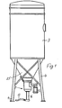
- a mixing and metering device designated as a whole by 1, hereinafter also referred to simply as a mixing device or only device 1, serves primarily to meter and mix bulk goods, in particular building materials, fertilizers or the like, and in the exemplary embodiment also to further process them or to transport these bulk goods.
- the device 1 has a drive motor 2 and also includes a loading or storage container or is attached to such a container, which in the exemplary embodiment is a silo 3 with feet 4 for its installation.
- the device 1 is on the attached lower outlet opening 5 of this silo 3, which is particularly clear in Figures 2 to 11. This outlet opening 5 opens directly into the mixing device 1.
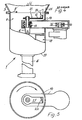
- the mixing shaft 6 for the mixing tool or tools 7 is arranged vertically below the outlet opening 5 of the storage container 3 and that the device 1 has a premixing chamber 8 with at least one premixing tool 9 (FIG. 2), 10 (FIG. 4 ) or 11 (Fig. 6) is connected upstream.
- the drive motor 2 is arranged on the side of the device 1 and connected to the vertical mixing shaft 6 via drive or transmission means to be described.
- the motor shaft 12 is arranged parallel to the mixing shaft 6 and connected to it via a chain drive.
- the sprockets 13 can be seen in each of the exemplary embodiments, while the chain itself is not shown for the sake of a better overview.
- the motor shaft 12 transversely to the mixing shaft 6 and to connect it to the latter by means of a bevel gear or spur gear or universal joint.
- the drive means 12 and 13 are arranged from the drive motor 2 to the mixing shaft 6 in a closed housing 14 projecting into the mixing device 1.
- the actual mixer with the mixing tool 7 is located coaxially below the premixing chamber 8, in the area of which at least one supply (not shown in detail) for liquid or mixing water can be provided.
- an opening 15 can be provided through which the mixing tool 7 attracts air, so that the mixed mixture also contains air bubbles and air pores, which not only verifies its conveyability improves, but later also leads, for example, to heat-insulating properties.
- a feed pump 16, preferably a screw pump is arranged coaxially to the mixing shaft 6 and can pump the prepared mixture to its destination.
- very large delivery distances can be achieved, so that a hose 17 connected to the pump 16 can have a correspondingly large length of up to approximately 60 meters, so that in the case of dressed plaster it is also relatively high Buildings can be operated from a single location.
- Fig. 2 it is provided that for the premixing of the still dry material between the mixing chamber 18, which has the mixing tool 7 and the liquid supply, and the storage container 3, at least one pre-mixing tool 9 arranged in this case on the mixing shaft 6 is provided.
- this premixing tool 9 is located below the housing 14 for the drive and above this housing 14 there is provided a roof-shaped guide device 19 running in its longitudinal direction, the ridge 2C of which is directed against the silo opening 5 and the greatest width of which is approximately that of the housing 14 for the drive means corresponds to what can be seen in Fig. 3. 2 this guide device 19 is also shown rotated by 90 ° in cross section to illustrate this cross section, but in reality it is arranged in the longitudinal direction of the housing 14. Fig.
- this guide device 19 can extend over the entire cross section of the premixing chamber 8 or only to the end of the housing 14.
- This guide device 19 halves the material stream emerging from the silo in two parts, so that one-sided emptying of the silo 3 is avoided.
- the bulk material flow divided in this way can be detected and mixed by the premixing tool 9, so that any segregation that may have occurred is counteracted.
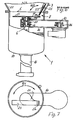
- FIGS. 4 and 6 show an embodiment in which a drive shaft, in this case the mixing shaft 6, projects upward above the housing 14 and carries at least one premixing tool 10 or 11 above this housing 14.
- a drive shaft in this case the mixing shaft 6
- the mixing shaft 6 projects upward above the housing 14 and carries at least one premixing tool 10 or 11 above this housing 14.
- the afterflow from the silo container 3 can be improved.
- These premixing tools 10 and 11 can be the only premixing tools, but they can also be combined with the premixing tool 9 below the housing 14 according to FIG. 2.
- FIG. 4 shows an embodiment with a fixed circumferential mixing finger 22 which, according to FIG. 5, is flat-iron-like and has a slightly oblique cross section in order to achieve a good stirring effect. It is indicated in dashed lines in FIG. 4 that this stirring finger can also protrude into the area of the opening 5 and somewhat higher, in order to facilitate the subsequent flow.
- FIG. 6 shows an embodiment in which a mixing blade 23 can protrude even higher into the silo 3 without, however, hindering the ability to mount and remove the device 1.
- a mixing blade 23 it is arranged above the drive means and the housing 14 Nete rotating body or arm 21 at least one in the region of its outer circumference about a hinge 24 swiveling or folding paddle 23, which is also arranged with its cross section obliquely to the direction of rotation according to the arrow Pf 1 in Fig. 7, so that it by the rotational movement within the Material such as a propeller or a screw automatically moves sideways and opens or collapses by rotating in opposite directions. This is indicated by the double arrow Pf 2 in Fig. 6. It can also be seen in Fig.
- the hinged agitator blade 23 forms an obtuse angle with its rotating body 21 in the working position and is approximately parallel to the funnel-shaped outlet area 25 of the silo 3, so that no bulk material can stick here, but also for a subsequent flow is taken care of from these marginal areas. Nevertheless, the stirrer blade 23 does not protrude into the silo area in the rest position, so that disassembly or a lateral pivoting of the device 1 to be described later, from the area of the outlet opening 5 of the silo 3, is not hindered by this in the working position in the silo projecting mixing tools. It should be mentioned that, as a premixing tool, two opposing, in particular hinged, stirring blades 23 can optionally also be attached to the rotary arm 21.
- the drive shaft of the motor 12 also has two driven gears, sprockets 26 or.
- a corresponding drive means in the exemplary embodiment a chain, not shown, with the corresponding sprocket 13 of the mixing shaft 6 and the other with a drive wheel 27 for the premixing tool 11 arranged above the housing 14 is connected. It can clearly be seen that the drive shaft 6 and a stub shaft 28 for the premixing tool 11 can be rotated independently of one another.
- the premixing tool 11 and the drive motor 2 on the one hand and the mixing shaft 6 and the drive motor 2 on the other hand can preferably have a lower speed than the mixing shaft 6.
- the agitator blades 23 open up to a considerably larger circumference and if the rotational speed remains the same, the circumferential speed would be too high.
- the peripheral speed can thus be adapted to the material in the silo 3 by reducing the speed.
- FIGS. 2, 4, 6, 9 and 11 show how the silo 3 can still be closed when the device 1 is to be moved out of the area of the outlet opening 5. It can be seen in these figures that the mixing device 1 can be pivoted away from the region of the outlet opening 5 parallel to itself via a rotary connection 29 arranged to the side of the silo 3 and its opening 5. This can be seen above all from the dashed representation in FIG. 8.
- the connecting or sealing flange 30 of the mixing device 1 has a plate-shaped extension 31 against its pivoting direction, which or the like when pivoting the mixing device 1 as a blind flange, slide. closes the outlet opening 5 of the silo 3 and has a corresponding size.
- the somewhat curved shape of this plate-shaped continuation 31 can be seen well from FIG. 8 and it is clear from the dashed illustration that this bulged plate 31 has a circular section on its outer contour, the center of which is the axis of rotation 29.
- the subsequent contour with a narrower radius of curvature corresponds approximately to the circumferential circle of the sealing flange 30 and can thus reliably close the outlet opening 5 in the position shown in broken lines.
- a separate slide 32 can be seen between the outlet opening 5 of the silo 3 and the entry into the mixing device 1 and the mixing device 1 can be folded down about a horizontal axis 33 from the outlet opening 5 of the silo 3.
- the slide 32 can be pivoted about an eccentric vertical axis of rotation 34 according to the double arrow in FIG. 10 under the outlet opening 5 or away from it. If it is in the position indicated by the broken line under the outlet opening 5, the device 1 can be folded down about its pivot axis 33 and cleaned or repaired in this position.
- the edge 35 facing the through opening 5 can either be rounded or even sharpened by the blind flange 31 connected to the mixing device 1 or the swivel slide 32.
- these parts can then more easily cut through the material column initially protruding through the outlet opening 5 into the mixer 1 during the pivoting movement described for carrying out the closure. 2 that the mixing device 1 in the area of the liquid supply under a partition 36 arranged between the premixing chamber 8 and the actual mixing chamber 18 on a turntable 37 has both upward and downward directed mixing tools 7, the diameter the mixing chamber 18 significantly exceeds its discharge opening 38.
- the lower face 39 of the mixing chamber is rounded at the transition to its outlet 38 and in particular to the feed pump 16 connected to it in a funnel shape or also partially beveled, and the adjacent mixing tools 7 have a corresponding bevel in this area.
- liquid should rise from the mixing chamber 18 in the event of any malfunctions, it reaches the premixing chamber and increases the resistance of the premixing tools, in particular a premixing tool 9. This results in a higher current consumption of the drive motor 2, so that a current consumption measuring device or a current limiting device is used on this motor can be provided, which can also shut down the liquid supply, but above all the motor, via a switch-off control or regulation, in order to switch off the entire mixing device 1 and to prevent the liquid from penetrating into the silo 3.
Landscapes
- Chemical & Material Sciences (AREA)
- Chemical Kinetics & Catalysis (AREA)
- Mixers Of The Rotary Stirring Type (AREA)
- Processing And Handling Of Plastics And Other Materials For Molding In General (AREA)
- Accessories For Mixers (AREA)
- Pharmaceuticals Containing Other Organic And Inorganic Compounds (AREA)
- Apparatuses For Bulk Treatment Of Fruits And Vegetables And Apparatuses For Preparing Feeds (AREA)
- Medicines Containing Material From Animals Or Micro-Organisms (AREA)
- Medicines Containing Plant Substances (AREA)
Priority Applications (1)
| Application Number | Priority Date | Filing Date | Title |
|---|---|---|---|
| AT84107561T ATE28583T1 (de) | 1983-07-21 | 1984-06-29 | Misch- und dosiervorrichtung fuer schuettgueter. |
Applications Claiming Priority (2)
| Application Number | Priority Date | Filing Date | Title |
|---|---|---|---|
| DE3326247 | 1983-07-21 | ||
| DE3326247A DE3326247C2 (de) | 1983-07-21 | 1983-07-21 | Vorrichtung zum kontinuierlichen Mischen eines Schüttgutes |
Publications (3)
| Publication Number | Publication Date |
|---|---|
| EP0134945A2 true EP0134945A2 (fr) | 1985-03-27 |
| EP0134945A3 EP0134945A3 (en) | 1985-07-24 |
| EP0134945B1 EP0134945B1 (fr) | 1987-07-29 |
Family
ID=6204503
Family Applications (1)
| Application Number | Title | Priority Date | Filing Date |
|---|---|---|---|
| EP84107561A Expired EP0134945B1 (fr) | 1983-07-21 | 1984-06-29 | Dispositif de mélange et de dosage pour matières en vrac |
Country Status (14)
| Country | Link |
|---|---|
| US (1) | US4576483A (fr) |
| EP (1) | EP0134945B1 (fr) |
| JP (1) | JPS6090031A (fr) |
| KR (1) | KR870001560B1 (fr) |
| AT (1) | ATE28583T1 (fr) |
| AU (1) | AU558783B2 (fr) |
| BR (1) | BR8403643A (fr) |
| CA (1) | CA1235413A (fr) |
| DE (2) | DE3326247C2 (fr) |
| ES (1) | ES8506466A1 (fr) |
| FI (1) | FI74651C (fr) |
| GR (1) | GR82262B (fr) |
| SU (1) | SU1271364A3 (fr) |
| ZA (1) | ZA845501B (fr) |
Cited By (1)
| Publication number | Priority date | Publication date | Assignee | Title |
|---|---|---|---|---|
| CN103418265A (zh) * | 2013-08-20 | 2013-12-04 | 顾璐璐 | 一种肥料混合搅拌装置 |
Families Citing this family (13)
| Publication number | Priority date | Publication date | Assignee | Title |
|---|---|---|---|---|
| DE3735951A1 (de) * | 1987-10-23 | 1989-05-03 | Dietrich Maurer | Verfahren zur herstellung von kalkmilch in beliebiger konzentration und menge, sowie einrichtung zur durchfuehrung des verfahrens |
| FR2883704B1 (fr) * | 2005-04-05 | 2007-06-01 | Vmi Sa | Dispositif de melange en continu d'une pate alimentaire comprenant deux types d'outils de melange superposes et evacuation laterale |
| US20110204611A1 (en) * | 2010-02-18 | 2011-08-25 | Daimler Trucks North America Llc | Fiber reinforced polymer frame rail |
| JP5791267B2 (ja) | 2010-12-02 | 2015-10-07 | Udトラックス株式会社 | 車両用シートのクッション構造 |
| EP3137272B1 (fr) | 2014-05-02 | 2023-11-15 | Construction Robotics, LLC | Système de distribution de mortier |
| CN108905845A (zh) * | 2018-07-04 | 2018-11-30 | 合肥欧语自动化有限公司 | 一种复合肥自动化混合搅拌生产设备 |
| DK3679777T3 (da) | 2019-01-09 | 2021-05-31 | Kverneland Group Nieuw Vennep Bv | Enhed til et doseringssystem for en spredemaskine til distribution af et granulært materiale eller lignende, doseringssystem og spredemaskine |
| CN110327839A (zh) * | 2019-06-18 | 2019-10-15 | 江苏合义化工新材料有限公司 | 复合型水煤浆添加剂制备装置 |
| CN110327836A (zh) * | 2019-06-18 | 2019-10-15 | 江苏合义化工新材料有限公司 | 高浓度水煤浆添加剂废水回收装置 |
| CN110959359A (zh) * | 2019-12-18 | 2020-04-07 | 刘璐 | 一种施肥用农业机械 |
| CN111661494A (zh) * | 2020-07-09 | 2020-09-15 | 新乡市嘉数科技有限公司 | 一种泵罐一体化液体或膏体输出装置 |
| CN113457489A (zh) * | 2021-08-12 | 2021-10-01 | 上海永德食品机械有限公司 | 一种可倾式真空搅拌罐 |
| CN116754754B (zh) * | 2023-08-08 | 2023-11-10 | 河北路诚检测技术有限公司 | 一种用于公路桥梁原材料检测的检测设备 |
Family Cites Families (12)
| Publication number | Priority date | Publication date | Assignee | Title |
|---|---|---|---|---|
| DE463559C (de) * | 1926-11-12 | 1928-07-30 | Karl Ludwig Dipl Ing | Mischmaschine, insbesondere fuer Moertel u. dgl. |
| US2249263A (en) * | 1937-09-20 | 1941-07-15 | Laval Separator Co De | Apparatus for treating oils |
| DE897836C (de) * | 1951-07-12 | 1953-11-23 | Karl Kranz Inh Wilhelm Heil & | Vorrichtung zum Mischen von trockenen Rohstoffen und Fluessigkeiten |
| US2953359A (en) * | 1958-10-16 | 1960-09-20 | Johnson March Corp | Apparatus for treating pulverulent material |
| CH473571A (fr) * | 1966-06-23 | 1969-06-15 | Legrain Michel A J | Appareil automatique pour préparer une nourriture fluide |
| US3523761A (en) * | 1966-10-04 | 1970-08-11 | Stratford Eng Corp | Reaction vessel with coil contact heat exchange |
| US3589686A (en) * | 1970-03-16 | 1971-06-29 | Susquehanna Corp | Aggregate treatment process and apparatus |
| DE2034837C3 (de) * | 1970-07-14 | 1973-12-06 | Bruno Meyer Spezialmaschinen- Und Wiegeapparatebau Gmbh, 5202 Hennef | Vorrichtung für die diskontinuier liehe Herstellung von Mischungen aus feinst bis grobkörnigen Schüttgütern |
| DE2340246A1 (de) * | 1973-08-09 | 1974-09-19 | Karl Dipl-Ing Schlecht | Kontinuierliche mischpumpe |
| US4175873A (en) * | 1976-09-10 | 1979-11-27 | Funken Co., Ltd. | Process and apparatus for mechanically mixing two immiscible liquids and one or more other substances |
| BG27604A1 (en) * | 1978-05-26 | 1979-12-12 | Velikov | Apparatus for dispersing of cement solutions |
| DE2935007C2 (de) * | 1979-08-30 | 1985-02-21 | Wachter Kg Hindelang Baustoffwerk Bautechnik, 8973 Hindelang | Vorrichtung zum kontinuierlichen Herstellen und Fördern von Putzmörtel o.dgl. |
-
1983
- 1983-07-21 DE DE3326247A patent/DE3326247C2/de not_active Expired
-
1984
- 1984-06-29 DE DE8484107561T patent/DE3465026D1/de not_active Expired
- 1984-06-29 AT AT84107561T patent/ATE28583T1/de not_active IP Right Cessation
- 1984-06-29 EP EP84107561A patent/EP0134945B1/fr not_active Expired
- 1984-07-10 GR GR75250A patent/GR82262B/el unknown
- 1984-07-16 AU AU30718/84A patent/AU558783B2/en not_active Ceased
- 1984-07-17 FI FI842867A patent/FI74651C/fi not_active IP Right Cessation
- 1984-07-17 ZA ZA845501A patent/ZA845501B/xx unknown
- 1984-07-19 US US06/632,431 patent/US4576483A/en not_active Expired - Fee Related
- 1984-07-20 BR BR8403643A patent/BR8403643A/pt unknown
- 1984-07-20 JP JP59149758A patent/JPS6090031A/ja active Pending
- 1984-07-20 ES ES534482A patent/ES8506466A1/es not_active Expired
- 1984-07-20 CA CA000459421A patent/CA1235413A/fr not_active Expired
- 1984-07-20 SU SU843773886A patent/SU1271364A3/ru active
- 1984-07-20 KR KR8404304A patent/KR870001560B1/ko not_active Expired
Cited By (1)
| Publication number | Priority date | Publication date | Assignee | Title |
|---|---|---|---|---|
| CN103418265A (zh) * | 2013-08-20 | 2013-12-04 | 顾璐璐 | 一种肥料混合搅拌装置 |
Also Published As
| Publication number | Publication date |
|---|---|
| AU3071884A (en) | 1985-01-24 |
| ES534482A0 (es) | 1985-08-01 |
| FI842867A0 (fi) | 1984-07-17 |
| ES8506466A1 (es) | 1985-08-01 |
| KR850001017A (ko) | 1985-03-14 |
| SU1271364A3 (ru) | 1986-11-15 |
| FI74651B (fi) | 1987-11-30 |
| EP0134945B1 (fr) | 1987-07-29 |
| DE3465026D1 (en) | 1987-09-03 |
| DE3326247C2 (de) | 1985-07-11 |
| BR8403643A (pt) | 1985-07-02 |
| JPS6090031A (ja) | 1985-05-21 |
| ATE28583T1 (de) | 1987-08-15 |
| FI74651C (fi) | 1988-03-10 |
| AU558783B2 (en) | 1987-02-05 |
| EP0134945A3 (en) | 1985-07-24 |
| US4576483A (en) | 1986-03-18 |
| DE3326247A1 (de) | 1985-02-07 |
| CA1235413A (fr) | 1988-04-19 |
| KR870001560B1 (en) | 1987-09-04 |
| ZA845501B (en) | 1985-03-27 |
| FI842867A7 (fi) | 1985-01-22 |
| GR82262B (fr) | 1984-12-13 |
Similar Documents
| Publication | Publication Date | Title |
|---|---|---|
| EP0134945B1 (fr) | Dispositif de mélange et de dosage pour matières en vrac | |
| DE2920025A1 (de) | Verfahren und vorrichtung zum kontinuierlichen mischen eines trockenfertigmoertels | |
| CH685157A5 (de) | Vorrichtung zur baustellenseitigen Herstellung von pumpfähigen Mörtelmassen. | |
| DE2147280C3 (de) | Vorrichtung zum Mischen von schüttbarem Erntegut | |
| DE19507181A1 (de) | Vorrichtung zum Mischen oder Kneten von organischen oder anorganischen Massen oder Teig | |
| DE2937469C2 (fr) | ||
| DE3604333A1 (de) | Einwellen-zwangsmischer | |
| DE10206270B4 (de) | Vorrichtung zum Mischen und Ausbringen von Schüttgut | |
| DE3444816C2 (de) | Beschickungsvorrichtung zum Zuführen pulvrigen Materials zu einer Förderleitung | |
| EP0988450B1 (fr) | Pompe a liquides epais comportant deux cylindres | |
| DE3631077A1 (de) | Mahlwalzwerk | |
| DE1932094A1 (de) | Vorrichtung zum Mischen pulverfoermiger und breiartiger Stoffe | |
| DE1684044C3 (de) | Fahrzeug mit Behältern zur Aufnahme von Betonkomponenten | |
| EP0606087B1 (fr) | Dispositif pour retirer, préparer et distribuer du fourrage pour bétail | |
| DE1114423B (de) | Transportmischer fuer Beton und andere Baustoffe | |
| DE3221949C2 (de) | Beton-Kolbenpumpe | |
| DE2951300C2 (de) | Siloaustragsvorrichtung für rieselfähige, pulverförmige bis körnige Feststoffe | |
| DE2043608C2 (de) | Tellermischer | |
| DE3011410A1 (de) | Maschine zum kontinuierlichen mischen und verspruehen von stoffen bzw. erzeugnissen fuer das verputzen und ueberziehen von gemauerten waenden | |
| DE3007490A1 (de) | Austrag- und dosiervorrichtung fuer insbesondere klumpenbildendes futter | |
| DE2523374A1 (de) | Vorrichtung zur kontinuierlichen herstellung von angemachtem moertel | |
| DE10333531A1 (de) | Vorrichtung zum Bereiten eines Gemisches, insbesondere für Spritzmaschinen | |
| DE3315099A1 (de) | Vorrichtung zum kontinuierlichen herstellen und foerdern eines gemisches aus trockengut und einer fluessigkeit | |
| DE19515390A1 (de) | Vorrichtung zum Aufbereiten von Mischgut | |
| DE19617660C2 (de) | Mischsilo |
Legal Events
| Date | Code | Title | Description |
|---|---|---|---|
| PUAI | Public reference made under article 153(3) epc to a published international application that has entered the european phase |
Free format text: ORIGINAL CODE: 0009012 |
|
| AK | Designated contracting states |
Designated state(s): AT BE CH DE FR GB IT LI LU NL SE |
|
| PUAL | Search report despatched |
Free format text: ORIGINAL CODE: 0009013 |
|
| AK | Designated contracting states |
Designated state(s): AT BE CH DE FR GB IT LI LU NL SE |
|
| 17P | Request for examination filed |
Effective date: 19850607 |
|
| 17Q | First examination report despatched |
Effective date: 19860319 |
|
| RAP1 | Party data changed (applicant data changed or rights of an application transferred) |
Owner name: M-TEC MATHIS TECHNIK GMBH |
|
| ITF | It: translation for a ep patent filed | ||
| GRAA | (expected) grant |
Free format text: ORIGINAL CODE: 0009210 |
|
| AK | Designated contracting states |
Kind code of ref document: B1 Designated state(s): AT BE CH DE FR GB IT LI LU NL SE |
|
| REF | Corresponds to: |
Ref document number: 28583 Country of ref document: AT Date of ref document: 19870815 Kind code of ref document: T |
|
| REF | Corresponds to: |
Ref document number: 3465026 Country of ref document: DE Date of ref document: 19870903 |
|
| ET | Fr: translation filed | ||
| PLBE | No opposition filed within time limit |
Free format text: ORIGINAL CODE: 0009261 |
|
| STAA | Information on the status of an ep patent application or granted ep patent |
Free format text: STATUS: NO OPPOSITION FILED WITHIN TIME LIMIT |
|
| PG25 | Lapsed in a contracting state [announced via postgrant information from national office to epo] |
Ref country code: GB Effective date: 19880629 Ref country code: AT Effective date: 19880629 |
|
| PG25 | Lapsed in a contracting state [announced via postgrant information from national office to epo] |
Ref country code: SE Effective date: 19880630 Ref country code: LU Free format text: LAPSE BECAUSE OF NON-PAYMENT OF DUE FEES Effective date: 19880630 Ref country code: LI Effective date: 19880630 Ref country code: CH Effective date: 19880630 |
|
| 26N | No opposition filed | ||
| BERE | Be: lapsed |
Owner name: M-TEC MATHIS TECHNIK G.M.B.H. Effective date: 19880630 |
|
| PG25 | Lapsed in a contracting state [announced via postgrant information from national office to epo] |
Ref country code: NL Effective date: 19890101 |
|
| NLV4 | Nl: lapsed or anulled due to non-payment of the annual fee | ||
| GBPC | Gb: european patent ceased through non-payment of renewal fee | ||
| PG25 | Lapsed in a contracting state [announced via postgrant information from national office to epo] |
Ref country code: FR Free format text: LAPSE BECAUSE OF NON-PAYMENT OF DUE FEES Effective date: 19890228 |
|
| REG | Reference to a national code |
Ref country code: CH Ref legal event code: PL |
|
| REG | Reference to a national code |
Ref country code: FR Ref legal event code: ST |
|
| PG25 | Lapsed in a contracting state [announced via postgrant information from national office to epo] |
Ref country code: BE Effective date: 19890630 |
|
| EUG | Se: european patent has lapsed |
Ref document number: 84107561.7 Effective date: 19890220 |
|
| PGFP | Annual fee paid to national office [announced via postgrant information from national office to epo] |
Ref country code: DE Payment date: 19960507 Year of fee payment: 13 |
|
| PG25 | Lapsed in a contracting state [announced via postgrant information from national office to epo] |
Ref country code: DE Free format text: LAPSE BECAUSE OF NON-PAYMENT OF DUE FEES Effective date: 19980303 |