EP0135275A2 - Réactivateur pour batterie de piles sèches - Google Patents
Réactivateur pour batterie de piles sèches Download PDFInfo
- Publication number
- EP0135275A2 EP0135275A2 EP84304713A EP84304713A EP0135275A2 EP 0135275 A2 EP0135275 A2 EP 0135275A2 EP 84304713 A EP84304713 A EP 84304713A EP 84304713 A EP84304713 A EP 84304713A EP 0135275 A2 EP0135275 A2 EP 0135275A2
- Authority
- EP
- European Patent Office
- Prior art keywords
- battery
- activator
- pulses
- dry cell
- activated
- Prior art date
- Legal status (The legal status is an assumption and is not a legal conclusion. Google has not performed a legal analysis and makes no representation as to the accuracy of the status listed.)
- Withdrawn
Links
Images

Classifications
-
- H—ELECTRICITY
- H02—GENERATION; CONVERSION OR DISTRIBUTION OF ELECTRIC POWER
- H02J—ELECTRIC POWER NETWORKS; CIRCUIT ARRANGEMENTS OR SYSTEMS FOR SUPPLYING OR DISTRIBUTING ELECTRIC POWER; SYSTEMS FOR STORING ELECTRIC ENERGY
- H02J7/00—Circuit arrangements for charging or discharging batteries or for supplying loads from batteries
- H02J7/02—Circuit arrangements for charging or discharging batteries or for supplying loads from batteries for charging batteries from AC mains by converters
-
- H—ELECTRICITY
- H02—GENERATION; CONVERSION OR DISTRIBUTION OF ELECTRIC POWER
- H02J—ELECTRIC POWER NETWORKS; CIRCUIT ARRANGEMENTS OR SYSTEMS FOR SUPPLYING OR DISTRIBUTING ELECTRIC POWER; SYSTEMS FOR STORING ELECTRIC ENERGY
- H02J2207/00—Details of circuit arrangements for charging or discharging batteries or supplying loads from batteries
- H02J2207/20—Charging or discharging characterised by the power electronics converter
Definitions
- the present invention relates to a dry cell battery re-activator.
- Dry cell batteries are a convenient and safe source of electrical energy. However, they are also expensive in that once discharged they are normally replaced.
- European Patent Application No. 0 047 183 discloses a re-activator which relies on the impedance of the battery to be re-activated to limit the period for which a cyclically varying d.c. current of 100Hz is applied to the battery.
- a battery is re-activated from a discharged state the period for which current is applied to it increases progressively as it approaches a fully charged state.
- the re-activation of the battery at a controlled rate ensures that gases are not evolved in the battery.
- this . thod of re-activating a battery is slow, especially where the battery is being re-activated from a fully discharged state.
- a dry cell battery re-activator comprising means for producing uni-directional pulses and inductive coupling means whereby the pulses are applied to a closed circuit comprising an inductive element and a battery to be re-activated.
- the battery to be re-activated looks like a leaky capacitor and therefore it forms with the inductive element a heavily damped resonant circuit. Thus each time a pulse is induced in the inductive element damped oscillations will occur in the reasonant circuit including the battery. Applicant believes that it is these damped oscillations applied to the battery as a result of each pulse that results in the high efficiency re-activation characteristic of the re-activator according to the present invention.
- the pulses are of high frequency, for example, 100 KHz,and are of relatively short duration.
- the pulses are produced by a blocking oscillator.
- the inductive coupling means comprises two inductively coupled windings, one of which is in the output of the means for producing said pulses and the other of which comprises the inductive element of said closed circuit.
- a blocking diode is provided in the said closed circuit.
- Preferably current limiting means are provided in the said closed circuit to limit the current to the battery to be re-activated according to its size.
- the re-activator comprises a blocking oscillator circuit 1, which is powered by a conventional d.c. power supply 2, consisting of a mains transformer 3, a bridge rectifier 4 and a smoothing capacitor 5.
- a conventional d.c. power supply 2 consisting of a mains transformer 3, a bridge rectifier 4 and a smoothing capacitor 5.
- the oscillator 1 comprises an NPN transistor 6, in the base circuit of which are connected, in series, an inductive winding 7 and a capacitor 8. Connected in the collector circuit of the transistor 6 is a second winding 9, which is inductively coupled to the inductive winding 7 in such a way as to introduce a phase shift of exactly zero between the input, i.e., the base circuit, and output, i.e., the collector circuit, of the transistor 6. Finally, a resistor 10 is connected between the base and the collector of the transistor 6, which provides the transistor 6 with bias.
- the oscillator 1 operates intermittently with base bias increasing during oscillation to a point where oscillations stop and then decreasing until oscillation is resumed.
- the output of the oscillator 1 i.e. in the collector circuit of transistor 6, uni-directional pulses are produced, the duration and frequency of which are determined by the resistor 10, and the inductive winding 7 and capacitor 8 respectively.
- the oscillator output present across winding 9, is inductively coupled to a third winding 11.
- the winding 11 is of high impedance compared with winding 9 and can have several times the number of turns of winding 9. Thus, it will be appreciated that the amplitude of the pulses induced in the open circuit winding 11 is very high.
- a battery to be re-activated (not shown) is connected across the winding 11, via a blocking arrangement consisting of a diode 12, shunted by a high value resistor 13, and an indicator arrangement consisting of an LED 14, shunted by a Zener diode 15.
- the battery to be re-activated is connected with its positive terminal towards the cathode of diode 12 and its negative terminal towards the free side of winding 11. Where appropriate current limiting means may also be connected in series with the battery.
- the battery to be re-activated appears across the winding 11 as a leaky capacitor and that accordingly, together with the inductive element of the winding 11, a dampe reasonant circuit is formed.
- a high frequency, damped, alternating voltage appears across the battery. Whilst applicant is unclear as to the exact processes which takes place within the battery during the period of each pulse applied thereto, applicant believes that it is the damped oscillations applied to the battery which results in the high efficiency re-activation characteristics of the re-activator according to the present invention.
- the mark/space ratio, frequency and amplitude of the uni-directional pulses may be varied to provide optimum performance of the re-activator for a particular battery.
- the frequency of the pulses is preferably high, for example 100KHzand the pulses are of relatively short duration.
- re-activator Whilst the re-activator has been described in relation to one battery it will be appriciated that it may be used to re-activate a number of batteries connected in series.
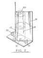
- a simple battery holder for use with the re-activator according to the present invention.
- the holder will accommodate, and provide connection to, one battery having positive and negative terminals at opposite ends with respect to on another or a number of batteries arranged end to end, in series.
- the holder comprises two conductive connectors 16 and 17, which are isolated from each other and provide connections to the positive and negative terminals of a battery or of a number of batteries connected in series.
- two batteries 18 are shown, stacked one on top of the other, and connected in series.
- Connector 16 is positioned in the base of the holder and connects with one side of the batteries 18 where they are stacked thereon.
- Connector 17 comprises a conductive strip which runs the length of the body 19 of the holder and which is exposed to the side of the body 19 in which the batteries 18 are stacked.
- the connector 17 is connected to the other side of the batteries 18 by means of connecting member 20, having the form of a right angle. As can be seen from Fig. 2, one side of the right angle rests on the other side of the batteries 18 from that resting on the connector 16 and the other side of the right angle rests upsgainst the conductive strip forming connector 17.
- the connectors 16 and 17 are in turn connected to terminals 21 and 22, which facilitate connection of the holder with the re-activator. If desired the current limiting means referred to hereinabove may also be mounted on the holder.
- the body 19 of the holder comprises two planar elements which are inclined to each other and interconnected to define a corner within which the connector 17 is located.
- the body 19 is inclined slightly to the vertical so that the batteries 18 and the connecting member 20 lean into the corner, thereby ensuring that the connecting member 20 makes electrical contact both with the uppermost battery 18 and the connector 17.
Landscapes
- Engineering & Computer Science (AREA)
- Power Engineering (AREA)
- Primary Cells (AREA)
- Secondary Cells (AREA)
Applications Claiming Priority (2)
| Application Number | Priority Date | Filing Date | Title |
|---|---|---|---|
| GB838319187A GB8319187D0 (en) | 1983-07-15 | 1983-07-15 | Dry cell battery re-activator |
| GB8319187 | 1983-07-15 |
Publications (2)
| Publication Number | Publication Date |
|---|---|
| EP0135275A2 true EP0135275A2 (fr) | 1985-03-27 |
| EP0135275A3 EP0135275A3 (fr) | 1986-12-17 |
Family
ID=10545782
Family Applications (1)
| Application Number | Title | Priority Date | Filing Date |
|---|---|---|---|
| EP84304713A Withdrawn EP0135275A3 (fr) | 1983-07-15 | 1984-07-11 | Réactivateur pour batterie de piles sèches |
Country Status (4)
| Country | Link |
|---|---|
| US (1) | US4629963A (fr) |
| EP (1) | EP0135275A3 (fr) |
| JP (1) | JPS61121721A (fr) |
| GB (1) | GB8319187D0 (fr) |
Cited By (8)
| Publication number | Priority date | Publication date | Assignee | Title |
|---|---|---|---|---|
| WO1987005452A1 (fr) * | 1986-03-04 | 1987-09-11 | Erik Denneborg | Appareil regenerateur de cellules primaires |
| GB2195843A (en) * | 1986-09-29 | 1988-04-13 | Re Gen Prod Ltd | Energy transformation apparatus |
| WO1990003059A1 (fr) * | 1988-09-01 | 1990-03-22 | Gbm Electronic Import Export Gmbh | Chargeur d'accumulateurs |
| GB2266728A (en) * | 1992-05-06 | 1993-11-10 | Orlando Augustus Robert Walden | Power supply to industrial electrolytic processes |
| EP0616410A3 (fr) * | 1993-03-17 | 1994-12-21 | Rotermund Ulli | Procédé et dispositif de régénération de sources de tension sous la forme d'éléments primaires. |
| WO1994029940A1 (fr) * | 1993-06-03 | 1994-12-22 | Innovations Group Limited | Chargeur pour elements de batteries seches |
| WO1997040544A1 (fr) * | 1996-04-24 | 1997-10-30 | Gm Racing Modellsportvertrieb Gmbh | Procede pour reduire la resistance interne d'accumulateurs rechargeables |
| DE10147386A1 (de) * | 2001-09-26 | 2003-04-24 | Alwin Kaiser | Verfahren und Ladevorrichtung zum Aufladen von wieder aufladbaren Batterien, insbesondere Lithium-Batterien |
Families Citing this family (7)
| Publication number | Priority date | Publication date | Assignee | Title |
|---|---|---|---|---|
| US5113127A (en) * | 1989-04-11 | 1992-05-12 | Solid State Chargers, Inc. | Universal battery charger |
| US5270635A (en) * | 1989-04-11 | 1993-12-14 | Solid State Chargers, Inc. | Universal battery charger |
| TW220014B (fr) * | 1992-07-23 | 1994-02-01 | Gali Carl E | |
| US5543702A (en) * | 1993-02-08 | 1996-08-06 | Jdp Innovations, Inc. | Alkaline battery charging method and battery charger |
| US5463304A (en) * | 1993-11-22 | 1995-10-31 | Winters; Thomas L. | Life extending circuit for storage batteries |
| US5633575A (en) * | 1994-03-31 | 1997-05-27 | Gali; Carl E. | Battery reclaimer and charger |
| TW200810318A (en) * | 2006-08-15 | 2008-02-16 | Chen zheng sheng | Voltage-recovering method for primary battery and apparatus of same |
Family Cites Families (6)
| Publication number | Priority date | Publication date | Assignee | Title |
|---|---|---|---|---|
| US3609502A (en) * | 1969-07-24 | 1971-09-28 | Mcculloch Corp | High frequency battery charger employing an inverter |
| US4021717A (en) * | 1973-05-16 | 1977-05-03 | Matsushita Electric Industrial Co., Ltd. | Charging system |
| GB1578922A (en) * | 1977-05-24 | 1980-11-12 | Contrology Tech Ltd | Battery charging equipment |
| SE408610B (sv) * | 1978-05-12 | 1979-06-18 | Rostlund Karl Johnie | Metod for uppladdning av torrbatterier, samt anordning for genomforande av metoden |
| SE419147B (sv) * | 1979-11-21 | 1981-07-13 | Rostlund K Jonnie | Anordning for laddning av torrbaterier eller ackumulatorbatterier med hjelp av vexelstrom |
| EP0047183A1 (fr) * | 1980-09-03 | 1982-03-10 | Reactomatic Limited | Rechargeur de batterie de piles sèches |
-
1983
- 1983-07-15 GB GB838319187A patent/GB8319187D0/en active Pending
-
1984
- 1984-07-11 EP EP84304713A patent/EP0135275A3/fr not_active Withdrawn
- 1984-10-31 US US06/666,970 patent/US4629963A/en not_active Expired - Fee Related
- 1984-11-13 JP JP59239305A patent/JPS61121721A/ja active Pending
Cited By (10)
| Publication number | Priority date | Publication date | Assignee | Title |
|---|---|---|---|---|
| WO1987005452A1 (fr) * | 1986-03-04 | 1987-09-11 | Erik Denneborg | Appareil regenerateur de cellules primaires |
| GB2195843A (en) * | 1986-09-29 | 1988-04-13 | Re Gen Prod Ltd | Energy transformation apparatus |
| WO1990003059A1 (fr) * | 1988-09-01 | 1990-03-22 | Gbm Electronic Import Export Gmbh | Chargeur d'accumulateurs |
| GB2266728A (en) * | 1992-05-06 | 1993-11-10 | Orlando Augustus Robert Walden | Power supply to industrial electrolytic processes |
| EP0616410A3 (fr) * | 1993-03-17 | 1994-12-21 | Rotermund Ulli | Procédé et dispositif de régénération de sources de tension sous la forme d'éléments primaires. |
| CN1050944C (zh) * | 1993-03-17 | 2000-03-29 | 乌利·罗特蒙特 | 使一次电池形式的电压源再生的方法及装置 |
| WO1994029940A1 (fr) * | 1993-06-03 | 1994-12-22 | Innovations Group Limited | Chargeur pour elements de batteries seches |
| WO1997040544A1 (fr) * | 1996-04-24 | 1997-10-30 | Gm Racing Modellsportvertrieb Gmbh | Procede pour reduire la resistance interne d'accumulateurs rechargeables |
| US5905363A (en) * | 1996-04-24 | 1999-05-18 | Gm Racing Modellsportvertrieb Gmbh | Method for reducing the internal resistance of rechargeable batteries |
| DE10147386A1 (de) * | 2001-09-26 | 2003-04-24 | Alwin Kaiser | Verfahren und Ladevorrichtung zum Aufladen von wieder aufladbaren Batterien, insbesondere Lithium-Batterien |
Also Published As
| Publication number | Publication date |
|---|---|
| US4629963A (en) | 1986-12-16 |
| JPS61121721A (ja) | 1986-06-09 |
| GB8319187D0 (en) | 1983-08-17 |
| EP0135275A3 (fr) | 1986-12-17 |
Similar Documents
| Publication | Publication Date | Title |
|---|---|---|
| EP0135275A2 (fr) | Réactivateur pour batterie de piles sèches | |
| US6972543B1 (en) | Series resonant inductive charging circuit | |
| US5276393A (en) | Solar radiation powered battery reclaimer and charger | |
| JPS58179892U (ja) | 高周波電源装置 | |
| US4709189A (en) | Transistor inverter device for fluorescent lamp | |
| CA1226617A (fr) | Dispositif de reactivation de piles seches | |
| JPS58189991A (ja) | 放電灯点灯装置 | |
| US4839786A (en) | DC-DC converter | |
| JP2000295783A (ja) | 充電装置の電源回路 | |
| EP0830808B1 (fr) | Dispositif de circuit electrique | |
| EP0221213B1 (fr) | Elévateur de puissance | |
| JPS6139860A (ja) | 1石式インバ−タ | |
| JPH0647101A (ja) | 電波検出装置 | |
| JPH01251591A (ja) | 半波放電検出回路 | |
| KR870003188Y1 (ko) | 전원회로 | |
| JPH0269304A (ja) | 交流駆動型パルスオゾナイザ | |
| SU1166263A1 (ru) | Устройство дл возбуждени гармонических колебаний в электрической сети переменного тока | |
| SU486407A1 (ru) | Устройство дл зар да аккумул торной батареи посто нным током | |
| CN1049077C (zh) | 无接点的电池充电装置 | |
| SU1401575A1 (ru) | Источник вторичного электропитани | |
| SU1379911A2 (ru) | Преобразователь посто нного напр жени | |
| JPS6023013Y2 (ja) | 超音波霧化装置 | |
| SU647664A1 (ru) | Устройство дл регулировани переменного напр жени | |
| JPS5925996U (ja) | インバ−タ装置 | |
| JPS5713971A (en) | Rectifying circuit |
Legal Events
| Date | Code | Title | Description |
|---|---|---|---|
| PUAI | Public reference made under article 153(3) epc to a published international application that has entered the european phase |
Free format text: ORIGINAL CODE: 0009012 |
|
| AK | Designated contracting states |
Designated state(s): AT BE CH DE FR GB IT LI LU NL SE |
|
| RAP1 | Party data changed (applicant data changed or rights of an application transferred) |
Owner name: RE-GEN PRODUCTS LIMITED |
|
| PUAL | Search report despatched |
Free format text: ORIGINAL CODE: 0009013 |
|
| AK | Designated contracting states |
Kind code of ref document: A3 Designated state(s): AT BE CH DE FR GB IT LI LU NL SE |
|
| 17P | Request for examination filed |
Effective date: 19870615 |
|
| 17Q | First examination report despatched |
Effective date: 19900209 |
|
| STAA | Information on the status of an ep patent application or granted ep patent |
Free format text: STATUS: THE APPLICATION IS DEEMED TO BE WITHDRAWN |
|
| 18D | Application deemed to be withdrawn |
Effective date: 19900620 |