EP0135568B1 - Installation de broyage fin pour experiences de laboratoire - Google Patents
Installation de broyage fin pour experiences de laboratoire Download PDFInfo
- Publication number
- EP0135568B1 EP0135568B1 EP84901059A EP84901059A EP0135568B1 EP 0135568 B1 EP0135568 B1 EP 0135568B1 EP 84901059 A EP84901059 A EP 84901059A EP 84901059 A EP84901059 A EP 84901059A EP 0135568 B1 EP0135568 B1 EP 0135568B1
- Authority
- EP
- European Patent Office
- Prior art keywords
- grinding
- shaft
- roller body
- housing
- cooling wind
- Prior art date
- Legal status (The legal status is an assumption and is not a legal conclusion. Google has not performed a legal analysis and makes no representation as to the accuracy of the status listed.)
- Expired
Links
- 238000000227 grinding Methods 0.000 title claims abstract description 29
- 238000009533 lab test Methods 0.000 title claims abstract 3
- 238000009434 installation Methods 0.000 title abstract 2
- 239000000463 material Substances 0.000 claims abstract description 26
- 238000001816 cooling Methods 0.000 claims description 16
- 230000006835 compression Effects 0.000 claims description 4
- 238000007906 compression Methods 0.000 claims description 4
- 230000000694 effects Effects 0.000 abstract description 2
- 238000010923 batch production Methods 0.000 abstract 1
- 230000007246 mechanism Effects 0.000 abstract 1
- 238000000034 method Methods 0.000 description 6
- 230000008569 process Effects 0.000 description 6
- 239000002994 raw material Substances 0.000 description 5
- 230000008878 coupling Effects 0.000 description 4
- 238000010168 coupling process Methods 0.000 description 4
- 238000005859 coupling reaction Methods 0.000 description 4
- 230000009471 action Effects 0.000 description 3
- 210000000056 organ Anatomy 0.000 description 3
- 229910000831 Steel Inorganic materials 0.000 description 2
- 238000004140 cleaning Methods 0.000 description 2
- 230000000875 corresponding effect Effects 0.000 description 2
- 230000001105 regulatory effect Effects 0.000 description 2
- 239000010959 steel Substances 0.000 description 2
- 229910001208 Crucible steel Inorganic materials 0.000 description 1
- 235000019738 Limestone Nutrition 0.000 description 1
- 230000035508 accumulation Effects 0.000 description 1
- 238000009825 accumulation Methods 0.000 description 1
- 239000004568 cement Substances 0.000 description 1
- 239000000919 ceramic Substances 0.000 description 1
- 239000003245 coal Substances 0.000 description 1
- 239000000571 coke Substances 0.000 description 1
- 238000010276 construction Methods 0.000 description 1
- 239000002826 coolant Substances 0.000 description 1
- 230000001419 dependent effect Effects 0.000 description 1
- 238000011161 development Methods 0.000 description 1
- 230000018109 developmental process Effects 0.000 description 1
- 239000006028 limestone Substances 0.000 description 1
- 238000004519 manufacturing process Methods 0.000 description 1
- 239000002184 metal Substances 0.000 description 1
- 238000002156 mixing Methods 0.000 description 1
- 238000012986 modification Methods 0.000 description 1
- 230000004048 modification Effects 0.000 description 1
- 238000007639 printing Methods 0.000 description 1
- 230000000750 progressive effect Effects 0.000 description 1
- 230000001737 promoting effect Effects 0.000 description 1
- 238000007670 refining Methods 0.000 description 1
- 230000000284 resting effect Effects 0.000 description 1
- 238000007790 scraping Methods 0.000 description 1
- 238000005549 size reduction Methods 0.000 description 1
- 239000007779 soft material Substances 0.000 description 1
- 238000003860 storage Methods 0.000 description 1
Images



Classifications
-
- B—PERFORMING OPERATIONS; TRANSPORTING
- B02—CRUSHING, PULVERISING, OR DISINTEGRATING; PREPARATORY TREATMENT OF GRAIN FOR MILLING
- B02C—CRUSHING, PULVERISING, OR DISINTEGRATING IN GENERAL; MILLING GRAIN
- B02C15/00—Disintegrating by milling members in the form of rollers or balls co-operating with rings or discs
- B02C15/16—Disintegrating by milling members in the form of rollers or balls co-operating with rings or discs with milling members essentially having different peripheral speeds and in the form of a hollow cylinder or cone and an internal roller or cone
-
- B—PERFORMING OPERATIONS; TRANSPORTING
- B02—CRUSHING, PULVERISING, OR DISINTEGRATING; PREPARATORY TREATMENT OF GRAIN FOR MILLING
- B02C—CRUSHING, PULVERISING, OR DISINTEGRATING IN GENERAL; MILLING GRAIN
- B02C19/00—Other disintegrating devices or methods
-
- B—PERFORMING OPERATIONS; TRANSPORTING
- B02—CRUSHING, PULVERISING, OR DISINTEGRATING; PREPARATORY TREATMENT OF GRAIN FOR MILLING
- B02C—CRUSHING, PULVERISING, OR DISINTEGRATING IN GENERAL; MILLING GRAIN
- B02C2/00—Crushing or disintegrating by gyratory or cone crushers
- B02C2/10—Crushing or disintegrating by gyratory or cone crushers concentrically moved; Bell crushers
Definitions
- the invention relates to a device for the fine comminution of, in particular, material samples for laboratory purposes with a fixed and a revolving comminution organ, each with a surface at a distance from one another and the material to be ground temporarily arranged between them, the comminution organs on the one hand having a cylinder jacket which is fixed against rotation and on the other hand a roller body rotating in the same axis is provided, between which the regrind is conveyed in an annular gap from a task on one end face of the roller body, in particular via depressions arranged on the roller body, to a discharge on the other end face of the roller body.
- a shredding device with the above generic features is known from FR-A 2 183 676.
- This design which is essentially designed as a mixing and refining device, is also used for comminution of regrind, which is conveyed on the way from the regrind feed to the regrind discharge via an axial annular gap arranged between it, between a fixed casing and a rotating roller body and thereby into the annular space both from the Jacket is crushed inwards as well as blow bars protruding outwards from the roller body.
- the invention is therefore based on the object of improving a comminution device of the type mentioned at the outset in such a way that it can be used for comparatively soft, hard and also the hardest materials without modifications.
- the device should be able to work continuously and the size reduction with respect to the grain size in the discharge should be able to be regulated to a very large extent.
- the task also includes the requirement for a compact design to adapt to the space available in laboratories and for a dustproof design.
- the laboratory operation is advantageously provided with a mill in which not only coal and coke as examples of comparatively soft materials, but also, for example, limestone, cement and very hard ores can be pulverized, the grain size of the task preferably up to can be up to 8 millimeters, while a grain size of up to about 10 microns can be achieved in the discharge.
- the difference in grain size does not always have to encompass the aforementioned range, but rather smaller ranges can also be set.
- the device records a hardness range of 3 - 10 degrees on the Mohs hardness scale.
- An essential feature of the device according to the invention is that, depending on the degree of hardness of the feed material, an adjustable, grinding grinding action is ensured, which is supported by a striking grinding action to the extent that the roller body rotating in the fixed cylinder jacket tumbles or prances within the jacket during operation Movements are carried out, but not the roller itself is caused to make these movements, but a corresponding effect is brought about by the fact that the cylinder jacket can move by a small amount relative to the roller, preferably under the influence of flexible components, for example mechanical compression springs or hydraulic ones Printing units.
- the movement processes in the device which are brought about in this way contribute to promoting the flow of material from the task to the discharge and also prevent it from sticking in the shredding area. Both dry and wet regrind can be processed.
- a support plate 12 is mounted on a table-like base frame 10 so that it can pivot about an axis 11 wearing.
- the support plate 12 with grinding device 13 and motor 14 can be tilted about the axis 1 by means of handles 15 (cf. FIG. 4), namely the tilting or swiveling angle is 90 degrees, all intermediate positions being infinitely adjustable.
- a scale 16 is used to precisely determine the angle of inclination a knurled wheel 17 which acts on a suitable clamping device (not shown) which fixes the support plate 12 in the desired position.
- the grinding device 13 consists of a tubular housing 18 made of cast steel or light metal, which is provided on the outside with numerous longitudinal cooling fins 19.
- the end faces of the housing 18 are closed by closure pieces 20, 21, which are designed differently and allow the task or the discharge of the goods in a manner to be described.
- a fixed comminution member in the form of a cylindrical shell 22 which cannot move relative to the housing 18 and is made, for example, of steel or ceramic.
- the inner surface of the jacket 22 is absolutely cylindrical and smooth, preferably very finely ground or polished.
- the housing 18 rests on bearing blocks 23, each of which is essentially formed by a helical compression spring 24, as a result of which the housing is both movable within limits and has a relatively upward tendency to exert force.
- a roller body 26 is arranged on an axially extending shaft 25, the outside diameter of which is so much smaller than the inside diameter of the cylinder jacket 22 that a cylindrical annular gap of approximately 0.2-0.4 between these two parts mm gap width arises.
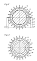
- the outer surface of the roller body 26 is also very finely smoothed or polished and, with the exception of two flats or chamfers 27, absolutely cylindrical.
- the chamfers 27 result from Fig. 2; they are arranged adjacent and abut one another in a roof-shaped manner, resulting in a narrow ridge surface 28 which extends in continuation of the outer surface of the roller body.
- the chamfers 27 create two adjacent longitudinal spaces 29 in the interior of the device, the cross section of which is essentially in the form of a segment of a circle.
- the roller body 26 consists in particular of steel and, if possible, has the same hardness as the cylinder jacket 22. The hardness of both comminution members 22, 26 should be greater than the hardness of the material to be comminuted.
- a cone body 20 as a pre-comminution member on the right end face of the roller body 26.
- the outer surface of the cone body 30 merges into the outer surface of the roller body 26, but is provided with triangular grooves 31 which run in the axial direction and run from a largest cross section at the narrow end of the cone body 30 to a smallest cross section at the wide end of this body.
- the inner surface of the cylinder jacket 22 can also be provided with correspondingly parallel grooves 32, as can be seen in FIG. 3.
- the combined roller-cone body 26, 30 is supported with its shaft 25 in smooth-running roller bearings 33, and the shaft 25 is in a fixed drive connection to the motor shaft of the electric motor 14 via a coupling 34. In this way, the motor conveys a revolving speed of 3000 rpm to the rotating comminution member 26 30.
- a cooling fan 35 which is also arranged on the support plate 12, can be driven by the same shaft 25 by the motor 14. The cooling fan generates an air flow over the housing 18 and its cooling fins 19.
- the closure pieces 20, 21 are designed accordingly for the task and the discharge of the regrind, namely the closure piece 20 arranged on the feed side is provided with a funnel 36 which extends into the upper half of the casing 22 in the region of the narrow end of the cone body 30 opens.
- the closure piece 21 on the discharge side of the housing 18 has a chamfer 37 on the inside, which opens into a lower opening 38 through which the comminuted material lusts the mill.
- the raw material first reaches the area of the cone body 30 from the mouth of the funnel 36, where a pre-comminution takes place.
- the grain size obtained must correspond to the annular gap between the jacket 22 and the roller body 26.
- a progressive comminution then takes place in this annular gap during the further passage in the direction of the closure piece 21, the material itself - although not exclusively - acting as a grinding tool.
- the longitudinal spaces 29 formed by the chamfers 27 serve essentially for transport in the radial direction and for preventing blockages due to clumping.
- the longitudinal edges of rooms 29 take part in the shredding to a certain extent like tools.
- the conveying of the millbase in the axial direction of the machine takes place only to a small extent under the influence of the constantly supplied raw material via the funnel 36, rather the conveyance is primarily caused by the gradient, which can be communicated to the housing 18 by tilting about the axis 11.
- the steeper the inclined position of the mill the faster the material passes through the various comminution zones, so that the length of time of the material between the comminution elements is a function of the angle of inclination.
- This means that the degree of comminution is usually dependent on the set gradient, although the hardness of the material also plays a role.
- Another aspect arises from the moisture content of the raw material; The more wet the raw material is fed in, the more finely the discharge is generally crushed.
- the scraping effect of the longitudinal edges of the chamfers 27 is significant, particularly in the case of wet goods, i.e. the edges act as wipers.
- the mounting of the housing 18 on the helical compression springs 24 plays an important role, because the jacket 22 is thereby pressed upwards and with the lower half of its inner surface against the lower half of the outer surface of the roller body 26. Since the housing 18 carries out prancing movements during operation, this occurs between the shredding organs signs of movement that influence the comminution. So that the vibrations of the housing 18 are kept within limits, especially when resonance vibrations cannot be ruled out, holding plates 39 are provided which surround the housing 18 with little play.
- FIGS. 1-4 a further embodiment is shown, the difference from the embodiment according to FIGS. 1-4 in particular in the design of the chassis or base and in the storage of the crushing elements and the electric motor.
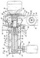
- This is a table-top device with a column 43 which rises on a footplate (not shown) and which is designed in the middle as a joint or pivot bearing 44.
- This has a scale 16 and a knurled wheel 17 which acts on a suitable clamping device (not shown) which fixes the comminution device in the desired position, for example in the inclined position shown in FIG. 5 by dash-dotted lines.
- the bearing in the embodiment according to FIGS. the roller body 26 is connected at only one end to the associated drive shaft, here the shaft 45, so that it protrudes into the cylinder jacket 22.
- the cylinder jacket 22 is also supported in a self-supporting manner, and the same arrangement principle is also implemented on the opposite side of the shaft 45, where the electric motor 14 with the rotor shaft 46 is located in a correspondingly self-supporting arrangement.
- the rotor shaft is supported in the conventional manner at its two ends in the motor stand (not shown).
- the upstanding column 43 is box-shaped hollow above the pivot bearing 44 and serves as a carrier for the shaft 45 and thus also for the self-supporting components arranged on both sides, namely the crushing elements 22, 26 and the motor 14 with rotor shaft 46 Wall of the upper part of the column 43 fastened in corresponding openings bearing flanges 47, 48, in which there are ball or roller bearings 49, 50, between which the shaft 45 extends.
- This shaft 45 is a hollow shaft in the form of a sleeve open on both sides with different inner diameters (cf. FIG. 6).
- the inside of the shaft 45 serves on the motor side for the positive reception of the rotor shaft 46 of the electric motor 14, while the shaft 45 is provided on the other side for receiving an axle stub 51 which is integral with the roller body 26. In this way, the shaft 45 forms a coupling connection between the motor 14 and the roller body 26.
- the shaft 45 On its outer circumference, the shaft 45 carries an impeller 52 of an axial fan, which rotates with the shaft 45.
- cooling wind is sucked in from below through the upper part of the column 43 according to the arrows 53 and, after being deflected and bundled at right angles, passed through a nozzle-shaped guide plate 54 via the comminution members 22, 26. While the suction openings for the cooling wind in the column 43 are not shown, the outlet openings for the used cooling medium from FIG. 6 result from the reference number 55.
- a sleeve-like housing 56 connects to the other flange 47, in which the comminution members 22, 26 with the filling funnel 36 and discharge tube 57 are accommodated .
- a bottle 58 is connected to the discharge pipe 57 as a collector for the comminuted material.
- the outer casing 59 of the cylindrical comminution member 22 is behind via the resilient bearing blocks 23 supported extensively so that the jacket 22 surrounding the roller body 26 can move in relation to the roller body, should this be necessary, for example, due to material accumulations or foreign bodies.
- the housing 56 is fastened to the column 43 by means of three clamping screws 60, which can be loosened in a conventional manner for removing the housing 56 and each pivoted outwards.
- the open edge of the housing is pushed over the correspondingly graduated outer edge 61 of the flange 47, the annular edge of the jacket 22 resting against a flexible seal 62, and the clamping screws 60 are then tightened.
- the casing 22 can be removed very easily from the roller body 26, for example for cleaning purposes or for exchange for another casing 22 which is more suitable for the next shredding process.
- the roller body 26 is also combined with a cone body 30 as a pre-comminution member.
- the outer surface of the cone body 30 merges into the outer surface of the roller body 26, as is also the case in the exemplary embodiment according to FIGS. 1-4.
- the stub shaft 51 connects here, with which the inner comminution member 26 is fastened to the shaft 45 in a slightly exchangeable manner.
- a grub screw 63 serves to secure the attachment.
- the processes take place as has already been described with reference to the exemplary embodiment according to FIGS. 1-4.
- the prancing movements of the jacket 22 or 59 mentioned there relative to the roller body 26 can be influenced by a regulating screw 64, which acts on the outer bearing block 23.
Landscapes
- Engineering & Computer Science (AREA)
- Food Science & Technology (AREA)
- Mechanical Engineering (AREA)
- Crushing And Grinding (AREA)
- Crushing And Pulverization Processes (AREA)
- Grinding Of Cylindrical And Plane Surfaces (AREA)
Abstract
Claims (19)
Priority Applications (1)
| Application Number | Priority Date | Filing Date | Title |
|---|---|---|---|
| AT84901059T ATE27923T1 (de) | 1983-03-02 | 1984-03-02 | Feinzerkleinerungsvorrichtung fuer laboratoriumszwecke. |
Applications Claiming Priority (2)
| Application Number | Priority Date | Filing Date | Title |
|---|---|---|---|
| DE3307323 | 1983-03-02 | ||
| DE19833307323 DE3307323A1 (de) | 1983-03-02 | 1983-03-02 | Feinzerkleinerungsvorrichtung fuer laboratoriumszwecke |
Publications (2)
| Publication Number | Publication Date |
|---|---|
| EP0135568A1 EP0135568A1 (fr) | 1985-04-03 |
| EP0135568B1 true EP0135568B1 (fr) | 1987-06-24 |
Family
ID=6192275
Family Applications (1)
| Application Number | Title | Priority Date | Filing Date |
|---|---|---|---|
| EP84901059A Expired EP0135568B1 (fr) | 1983-03-02 | 1984-03-02 | Installation de broyage fin pour experiences de laboratoire |
Country Status (7)
| Country | Link |
|---|---|
| US (1) | US4688727A (fr) |
| EP (1) | EP0135568B1 (fr) |
| JP (1) | JPS60501146A (fr) |
| AU (1) | AU567446B2 (fr) |
| DE (3) | DE3307323A1 (fr) |
| SU (1) | SU1433395A3 (fr) |
| WO (1) | WO1984003453A1 (fr) |
Cited By (1)
| Publication number | Priority date | Publication date | Assignee | Title |
|---|---|---|---|---|
| CN106334613A (zh) * | 2016-09-23 | 2017-01-18 | 重庆市红槽坊酒业有限公司 | 制酒原料研磨装置 |
Families Citing this family (18)
| Publication number | Priority date | Publication date | Assignee | Title |
|---|---|---|---|---|
| EP0555901B2 (fr) * | 1992-02-12 | 1999-12-01 | Unilever N.V. | Séparation pneumatique de farine |
| DE69301160T3 (de) * | 1992-02-12 | 2000-05-25 | Unilever N.V., Rotterdam | Sichten von Mehl |
| US5794865A (en) * | 1995-07-25 | 1998-08-18 | Didion Manufacturing Company | Rotary crusher/reclaimer for reclaiming and reclassifying sand and related aggregates from lump materials |
| US5813618A (en) * | 1995-11-28 | 1998-09-29 | Andritz Sprout-Bauer, Inc. | Continuous cyclindrical wood pulp refiner |
| RU2185885C2 (ru) * | 2000-05-25 | 2002-07-27 | Институт горного дела Севера СО РАН | Способ дезинтеграции горных пород и роторная мельница для его осуществления |
| US20040053319A1 (en) * | 2002-09-17 | 2004-03-18 | Mcwilliams Diana R. | Isolation of genetic molecules from a complex biological constrauct for use in genetic expression analysis |
| US7942354B2 (en) * | 2008-07-29 | 2011-05-17 | Didion Manufacturing Company | Rotary tumbler and metal reclaimer |
| US8528846B2 (en) * | 2009-10-15 | 2013-09-10 | General Kinematics Corporation | Vibratory crushing apparatus |
| CN102049335B (zh) * | 2009-11-06 | 2012-07-04 | 五冶集团上海有限公司 | 大型球磨机安装施工方法 |
| US8016218B1 (en) | 2011-03-16 | 2011-09-13 | Mitchell Friedman | Linear specimen shaker |
| JP5903599B2 (ja) * | 2011-10-06 | 2016-04-13 | パナソニックIpマネジメント株式会社 | 平板状表示装置の解体方法 |
| ITTO20110907A1 (it) * | 2011-10-12 | 2013-04-13 | Rancilio Group Spa | Dispositivo per macinare grani tostati |
| CN110124789A (zh) * | 2019-05-27 | 2019-08-16 | 淄博创立机电科技有限公司 | 一种固体废物处理粉碎设备 |
| DE102020101523B4 (de) * | 2019-09-06 | 2026-02-12 | Retsch Gmbh | Laborschwingmühle |
| CN110947495B (zh) * | 2019-12-04 | 2021-09-17 | 江巧巧 | 一种添加草本植物的化妆品颗粒状原料加工设备 |
| CN114209620A (zh) * | 2021-12-03 | 2022-03-22 | 江苏津沂菊源生物健康产业研究院有限公司 | 一种金丝皇菊纳米脂质体高渗透护肤品的制备工艺及装置 |
| CN114453106A (zh) * | 2022-02-11 | 2022-05-10 | 安徽省美极调味食品有限公司 | 一种用于复合调味料的加工设备 |
| CN115372069B (zh) * | 2022-10-25 | 2023-01-24 | 成都兰腾科技有限公司 | 一种检测样本取样用机械手机构 |
Family Cites Families (13)
| Publication number | Priority date | Publication date | Assignee | Title |
|---|---|---|---|---|
| US35036A (en) * | 1862-04-22 | Improvement in metallic grinding-mills | ||
| FR1115210A (fr) * | 1954-12-01 | 1956-04-20 | Machine destinée à préparer les peintures et autres enduits de nature liquide | |
| US3151817A (en) * | 1960-08-05 | 1964-10-06 | Nordberg Manufacturing Co | Replaceable wearing parts for crushers with tilting bowls |
| FR1328996A (fr) * | 1962-04-25 | 1963-06-07 | Appareil frotteur et malaxeur destiné notamment au traitement des sables de fonderie | |
| US3154257A (en) * | 1962-10-22 | 1964-10-27 | Magnetic Film And Tape Company | Impact-type mixer |
| US3570775A (en) * | 1967-12-21 | 1971-03-16 | Gen Electric | Mica delamination |
| US3622086A (en) * | 1968-10-28 | 1971-11-23 | Takashi Yamagishi | Pulverizer |
| US3806050A (en) * | 1971-05-12 | 1974-04-23 | E Cumpston | Mixer-refiner |
| CA974980A (en) * | 1972-05-09 | 1975-09-23 | Edward H. Cumpston (Jr.) | Mixer-refiner having automatic throughput control |
| US4067503A (en) * | 1976-04-12 | 1978-01-10 | Broman John S | Method of grinding in a mill |
| US4373674A (en) * | 1979-02-14 | 1983-02-15 | Marion Barrera | Crushing method and apparatus |
| US4307846A (en) * | 1979-10-09 | 1981-12-29 | Spelsberg Thomas C | Continuous flow tissue homogenizer |
| IT1141532B (it) * | 1980-04-09 | 1986-10-01 | Gabriele Rossi | Procedimento e macchina ad asse inclinato per pestellamento di prodotti e/o sostanze di qualunque tipo in sostituzione del classico mortaio completo di pestello a funzionamento manuale per uso culinario,erboristico e di laboratorio |
-
1983
- 1983-03-02 DE DE19833307323 patent/DE3307323A1/de not_active Withdrawn
-
1984
- 1984-03-02 DE DE84DE8400043T patent/DE3490095D2/de not_active Expired
- 1984-03-02 DE DE8484901059T patent/DE3464335D1/de not_active Expired
- 1984-03-02 JP JP59501114A patent/JPS60501146A/ja active Pending
- 1984-03-02 WO PCT/DE1984/000043 patent/WO1984003453A1/fr not_active Ceased
- 1984-03-02 US US06/677,217 patent/US4688727A/en not_active Expired - Fee Related
- 1984-03-02 EP EP84901059A patent/EP0135568B1/fr not_active Expired
- 1984-03-02 AU AU25784/84A patent/AU567446B2/en not_active Ceased
- 1984-11-01 SU SU843808262A patent/SU1433395A3/ru active
Cited By (1)
| Publication number | Priority date | Publication date | Assignee | Title |
|---|---|---|---|---|
| CN106334613A (zh) * | 2016-09-23 | 2017-01-18 | 重庆市红槽坊酒业有限公司 | 制酒原料研磨装置 |
Also Published As
| Publication number | Publication date |
|---|---|
| AU2578484A (en) | 1984-09-28 |
| JPS60501146A (ja) | 1985-07-25 |
| DE3307323A1 (de) | 1984-09-06 |
| AU567446B2 (en) | 1987-11-19 |
| DE3464335D1 (en) | 1987-07-30 |
| DE3490095D2 (en) | 1985-03-21 |
| SU1433395A3 (ru) | 1988-10-23 |
| US4688727A (en) | 1987-08-25 |
| WO1984003453A1 (fr) | 1984-09-13 |
| EP0135568A1 (fr) | 1985-04-03 |
Similar Documents
| Publication | Publication Date | Title |
|---|---|---|
| DE3311433A1 (de) | Klassieren von mahlgut von vertikalen rollenmuehlen | |
| EP1287878A2 (fr) | Appareil de traitement des materiaux | |
| DE3307323A1 (de) | Feinzerkleinerungsvorrichtung fuer laboratoriumszwecke | |
| DE2633520A1 (de) | Mahlmaschine fuer feststoffe | |
| DE3131370A1 (de) | Ruehrwerkskugelmuehle | |
| DE4213608C2 (de) | Vorrichtung zum Zerkleinern von Gummibrocken | |
| DE1245257B (de) | Vorrichtung zum Zerkleinern von insbesondere festen, koernerartigen Stoffen | |
| EP0015877A1 (fr) | Dispositif de broyage d'ordures et procédé de fonctionnement dudit dispositif | |
| DE3324467A1 (de) | Zerkleinerungseinrichtung fuer koerniges und faseriges gut sowie halmgut | |
| DE1932094A1 (de) | Vorrichtung zum Mischen pulverfoermiger und breiartiger Stoffe | |
| EP0567759A2 (fr) | Dispositif pour pulvériser des morceaux de caoutchouc | |
| DE20007786U1 (de) | Zerkleinerungswalze | |
| DE3105558A1 (de) | Zerhackervorrichtung fuer einen konus-schnecken-mischer | |
| DE2831641C2 (de) | Vorrichtung zum Zerkleinern von feuchter Abfallmasse | |
| DE588855C (de) | Rohrmuehle mit Mahlwalzen als Mahlkoerper | |
| DE2814778B2 (de) | Zerkleinerungsmaschine für Schüttgüter | |
| DE19530428C1 (de) | Granulatmühle | |
| DE625874C (de) | Prallzerkleinerer zur Vermahlung von koernigen Stoffen, wie Getreide o. dgl. | |
| DE7512389U (de) | Rohrmuehle | |
| DE750963C (de) | Vorrichtung zum Zerkleinern, Verreiben, Mischen od. dgl. | |
| DE7218596U (de) | Zerkleinerungsvorrichtung mit pneumatischer austragung des zerkleinerten gutes | |
| DE700473C (de) | Mahl- und Zerkleinerungsvorrichtung | |
| DE8714117U1 (de) | Vorrichtung zum Zerkleinern von Müll od. dgl. Haufwerk | |
| DE959701C (de) | Vorrichtung zum Zerkleinern und Verfeinern von Papierstoff | |
| CH676938A5 (en) | Refuse breaking machine with cylindrical housing |
Legal Events
| Date | Code | Title | Description |
|---|---|---|---|
| PUAI | Public reference made under article 153(3) epc to a published international application that has entered the european phase |
Free format text: ORIGINAL CODE: 0009012 |
|
| 17P | Request for examination filed |
Effective date: 19841030 |
|
| AK | Designated contracting states |
Designated state(s): AT BE CH DE FR GB LI LU NL SE |
|
| GRAA | (expected) grant |
Free format text: ORIGINAL CODE: 0009210 |
|
| AK | Designated contracting states |
Kind code of ref document: B1 Designated state(s): AT BE CH DE FR GB LI LU NL SE |
|
| PG25 | Lapsed in a contracting state [announced via postgrant information from national office to epo] |
Ref country code: NL Effective date: 19870624 Ref country code: BE Effective date: 19870624 |
|
| REF | Corresponds to: |
Ref document number: 27923 Country of ref document: AT Date of ref document: 19870715 Kind code of ref document: T |
|
| PG25 | Lapsed in a contracting state [announced via postgrant information from national office to epo] |
Ref country code: SE Effective date: 19870630 |
|
| REF | Corresponds to: |
Ref document number: 3464335 Country of ref document: DE Date of ref document: 19870730 |
|
| ET | Fr: translation filed | ||
| NLV1 | Nl: lapsed or annulled due to failure to fulfill the requirements of art. 29p and 29m of the patents act | ||
| PG25 | Lapsed in a contracting state [announced via postgrant information from national office to epo] |
Ref country code: AT Effective date: 19880302 |
|
| PG25 | Lapsed in a contracting state [announced via postgrant information from national office to epo] |
Ref country code: LU Free format text: LAPSE BECAUSE OF NON-PAYMENT OF DUE FEES Effective date: 19880331 Ref country code: LI Effective date: 19880331 Ref country code: CH Effective date: 19880331 |
|
| PLBE | No opposition filed within time limit |
Free format text: ORIGINAL CODE: 0009261 |
|
| STAA | Information on the status of an ep patent application or granted ep patent |
Free format text: STATUS: NO OPPOSITION FILED WITHIN TIME LIMIT |
|
| 26N | No opposition filed | ||
| REG | Reference to a national code |
Ref country code: CH Ref legal event code: PL |
|
| PGFP | Annual fee paid to national office [announced via postgrant information from national office to epo] |
Ref country code: GB Payment date: 19910314 Year of fee payment: 8 Ref country code: FR Payment date: 19910314 Year of fee payment: 8 |
|
| PGFP | Annual fee paid to national office [announced via postgrant information from national office to epo] |
Ref country code: DE Payment date: 19910321 Year of fee payment: 8 |
|
| PG25 | Lapsed in a contracting state [announced via postgrant information from national office to epo] |
Ref country code: GB Effective date: 19920302 |
|
| GBPC | Gb: european patent ceased through non-payment of renewal fee | ||
| PG25 | Lapsed in a contracting state [announced via postgrant information from national office to epo] |
Ref country code: FR Effective date: 19921130 |
|
| PG25 | Lapsed in a contracting state [announced via postgrant information from national office to epo] |
Ref country code: DE Effective date: 19930101 |
|
| REG | Reference to a national code |
Ref country code: FR Ref legal event code: ST |