EP0135615A2 - Verfahren und Vorrichtung hinsichtlich Mustererkennung - Google Patents
Verfahren und Vorrichtung hinsichtlich Mustererkennung Download PDFInfo
- Publication number
- EP0135615A2 EP0135615A2 EP83111969A EP83111969A EP0135615A2 EP 0135615 A2 EP0135615 A2 EP 0135615A2 EP 83111969 A EP83111969 A EP 83111969A EP 83111969 A EP83111969 A EP 83111969A EP 0135615 A2 EP0135615 A2 EP 0135615A2
- Authority
- EP
- European Patent Office
- Prior art keywords
- stroke
- patterns
- pattern
- algorithmic
- vocabulary
- Prior art date
- Legal status (The legal status is an assumption and is not a legal conclusion. Google has not performed a legal analysis and makes no representation as to the accuracy of the status listed.)
- Ceased
Links
Images




Classifications
-
- G—PHYSICS
- G06—COMPUTING OR CALCULATING; COUNTING
- G06V—IMAGE OR VIDEO RECOGNITION OR UNDERSTANDING
- G06V30/00—Character recognition; Recognising digital ink; Document-oriented image-based pattern recognition
- G06V30/10—Character recognition
- G06V30/24—Character recognition characterised by the processing or recognition method
- G06V30/242—Division of the character sequences into groups prior to recognition; Selection of dictionaries
-
- G—PHYSICS
- G06—COMPUTING OR CALCULATING; COUNTING
- G06V—IMAGE OR VIDEO RECOGNITION OR UNDERSTANDING
- G06V30/00—Character recognition; Recognising digital ink; Document-oriented image-based pattern recognition
- G06V30/10—Character recognition
- G06V30/22—Character recognition characterised by the type of writing
- G06V30/226—Character recognition characterised by the type of writing of cursive writing
-
- G—PHYSICS
- G06—COMPUTING OR CALCULATING; COUNTING
- G06V—IMAGE OR VIDEO RECOGNITION OR UNDERSTANDING
- G06V30/00—Character recognition; Recognising digital ink; Document-oriented image-based pattern recognition
- G06V30/10—Character recognition
- G06V30/24—Character recognition characterised by the processing or recognition method
- G06V30/248—Character recognition characterised by the processing or recognition method involving plural approaches, e.g. verification by template match; Resolving confusion among similar patterns, e.g. "O" versus "Q"
Definitions
- the invention is concerned with pattern processing.
- the most significant field involves patterns used in human communication. Aspects are as simple as typewriting or typesetting which at this time may entail only simple mechanical apparatus for replicating a selected inscribed character in another medium. Others are more sophisticated and the human interface may be only an initial step. Examples include word processing in which application of extensive artificial intelligence follows inputting.
- Ideographic languages such as Kanji, are a prime example.
- Input would be accomplished by writing characters exactly as they are conventionally written. Registration equipment, such as an appropriately equipped pen and/or tablet would convert characters into electrical impulses conveying x-y coordinate information. These impulses then constitute the input which would be processed and ultimately subjected to recognition programs involving matching with information in memory.
- Disambiguation routines are designed only to differentiate members of confusion sets of characters. Each routine is designed for application to a specific character in the dictionary and looks for specific identifying characteristic(s) to qualify a character.
- Handwriting recognition or more generally, pattern recognition, required in all systems and apparatus in accordance with this invention necessarily depend both on the algorithmic procedures familiar to the ordinary programmer and to the "disambiguation" procedures (which are non-algorithmic, i.e., are not uniformly applied to all patterns but only for the character for which designed). Disambiguation depends to a large extent on human judgment derived from actual experience in differentiating members of confusion sets.
- Systems and apparatus of the invention depend on design of algorithmic steps which if used without disambiguation (without non-algorithmic steps) result in deliberate development of confused sets of characters (avoids unique recognition by algorithmic phase processing alone).
- An absolute minimum requirement is an average of two characters per confusion set as yielded by'algorithmic part processing alone with such sets yielded for at least half the entries. This minimum applies to relatively simple tasks as, for example, non-cursive English.
- a more usual confusion set as yielded by algorithmic processing alone includes' at least three or four or five or even ten characters, and fewer than one out of five or ten and preferably thirty entries results in unique recognition.
- the desired average for JOYO upon application of algorithmic routines alone is at least five members per confusion set.
- the required average and permitted unique recognitions scale at least linearly with vocabulary size.
- the disambiguation procedures simulate human experience.
- This "human intelligence" set of routines is designed to distinguish members of confusion sets.
- Actual experience with an embodiment of the invention demonstrates that the required looseness in the algorithmic part is sufficient to accommodate usually encountered variations in writing habits.
- inventive approach will, at least initially, be of greatest value as used with complex non-alphabet languages, it may be expected to find other uses. These include processing of cursive alphabetic writing as well as lettering and numbering in general. Useful processes and/or apparatus in accordance with the invention are expected to be applied to varieties of patterns that do not find use in human language.
- disambiguation procedure that is, the procedure which in forward processing follows dictionary matching in which, in general, a "confusion set" of characters (rather than a unique character) is identified.
- the disambiguation procedure is non-algorithmic, that is, routines are uniquely applied to particular characters.
- routines are applied only to characters in confusion sets. If disambiguation is applied before dictionary matching the routines are necessarily applied to larger numbers of characters, e.g., all dictionary characters to be compared with a particular entry.
- uniform criteria are applied to large groups or to all characters up to and including dictionary matching.
- disambiguation which in forward processing follows dictionary matching, use is made of criteria specific to members of confusion sets as identified and made part of memory. Use of such specific criteria constitute a "human intelligence" phase of the invention. This phase is also described as "non-algorithmic".
- a preferred embodiment was briefly described in the summary. It depends on stroke shape and sequence in the algorithmic phase and uses interstroke characteristics only during the non-algorithmic phase.
- disambiguation criteria and algorithmic criteria may be interposed.
- algorithmic criteria may be based on spatial relationship of strokes (relative coordinate positions) as well as on presence or absence of intercepts, and disambiguation may take the form of intrastroke characteristics such as stroke shape.
- stroke shape is utilized in disambiguation as in any disambiguation routine in accordance with the invention, criteria are applied to a particular character.
- spatial criteria are uniformly applied to all or large sets of characters, and disambiguation uses shape characteristics of stroke(s) of a particular character.
- disambiguation may also utilize interstroke characteristics omitted from the algorithmic phase.
- disambiguation may be based on criteria such as presence or absence of an intercept as between two particular strokes, e.g., strokes 3 and 8
- disambiguation may rely on -- e.g., upward concavity of a stroke -- e.g., stroke type 8.
- Sound may also be used in algorithmic or non-algorithmic processing.
- a Chinese rather than Japanese pronunciation of Kanji characters is common, for example, for construction of phonetic dictionaries in book form, and this practice is preferred in this inventive embodiment as well.
- Disambiguation is characterized by judgmental decision. It may be that the judgmental decision regards characteristics which are, themselves, difficult to reduce to algorithmic relationships or it may be that they are easily expressed in mathematical terms. In the latter event, judgment may depend upon the determination to apply or not apply a particular mathematics criterion, always in view of the specific problem on hand--designation of one ore more characteristics which serve to differentiate an entry from the associated members of a confusion set yielded during the algorithmic phase.
- the required number of (a) maximum permitted unique solutions and (b) minimum average number of members per confusion set are set forth in terms of (c) vocabulary size in the Summary of the Invention.
- Preferred embodiments are tabulated: with further increase in vocabulary resulting in linearly increased confusion set size. Preferred limits correspond with greater emphasis on the non-algorithmic phase (on disambiguation). A more preferred confusion set size is 50 percent greater than that indicated above with a still more preferred limit corresponding with 100 percent increase.
- Kanji vocabulary sets are in terms of stroke count so that, e.g., only ten stroke dictionary entries are considered upon inputting of a ten stroke pattern.
- stroke count distribution is considered approximately Gaussian, peaking at about eleven strokes and tailing at one stroke and in the high twenties. The permitted unique solutions generally occur at or near the tails while confusion sets are generally largest at or near the peak.
- JOYO an average minimum number of five confusion set members corresponds with at least seven for the eleven-stroke vocabulary set.
- inventive systems are two phase with one phase corresponding with the "algorithmic", routines, and the second phase corresponding with the "non-algorithmic" routines. It has also been found useful to depend upon the natural difference in confusion degree as related to stroke number. Where, for example, a small number of characters use a particular number of strokes, e.g., fifteen to twenty-five, so that less confusion is to be expected for characters in this category, algorithmic decision criteria may be loosened. For less complex characters, where the number of characters in vocabulary begin'to increase, less deviation may be permitted. Experience with preferred embodiments has shown the wisdom of actually disregarding completely all strokes beyond a certain stroke count.
- stroke labeling may be accomplished by use of routines in which permitted deviation differs from point to point.
- Step 2 preprocessing may include a number of operations.
- less meaningful writing deviations are eliminated, for example, by filtering and data smoothing. It has been found useful in the preferred embodiment to convert time-sampled data points into spatially sampled points. Analog-to-digital conversion, if needed, may be carried out at this stage or earlier if needed.
- each stroke is labeled with a stroke category label, or, alternatively, if an input stroke is not identified, with a question mark.
- Emphasis plays a significant role at the stroke recognition stage. Certain input strokes are identified with increased specificity.
- Stroke confusion groups may include separately identifiable strokes which are easily confused--or, alternatively, may be designed to accommodate stroke variants corresponding with variations in writing style.
- stroke recognition includes a first operation in which strokes are identified as “simple” or “complex". Acceptance as “simple” at this stage (level 0) permits identification as, for example, Horizontal, Vertical, or Diagonal. Experience'with Kanji indicates that at least eighty percent of all strokes may be properly labeled as "simple” at this "zero" level.
- Templates in the embodiment under discussion include point-by-point tolerance acceptance. For example, if in angular terms, tolerances may be expressed as permitted angular ranges.
- level 1 if initial template matching is designated “level 1", it may be followed by a number of additional levels (level 2, level 3%) generally designed to account for further variations in writing style.
- level 2, level 3 if initial template matching is designated "level 1”, it may be followed by a number of additional levels (level 2, level 3%) generally designed to account for further variations in writing style.
- accommodation of different writing styles may take the form of sequential operations in which strokes, defined in angular values, are translated or rotated by a specified amount in angular or “theta space”. This is an overall shift as contrasted to the point-by-point deviations of "level 1".
- Overall shift is in terms of translation or rotation of strokes plotted in terms of absolute angle in degree for each stroke point on one coordinate and point number (1, 2, 3.%) on the other coordinate.
- a complete process may provide for more than one translation and/or rotation of sequentially increasing magnitude.
- Dictionary matching in the embodiment under discussion is the procedure whereby the stroke labels produced in the recognition stage are compared with similar entries in memory.
- further information may be rejected in the interest of avoiding further confusion.
- Advantage may be taken of characters which can be accurately identified without need for the specificity of a particular stroke label at every stroke position. In extreme instances--for many-stroke characters, any stroke category label (even including a question mark) may be accepted.
- Pattern Two-dimensional design made up of one or more strokes which is intended to convey meaning. Patterns include, but are not restricted to, alphabetic or non-alphabetic representations of characters used in human communication.
- Character A pattern, such as an alphabetic letter, a number, or an ideogram which has some accepted meaning, such as a JIS designation and is therefore useful in human communication.
- Stroke Continuous "lines” of any shape of which patterns are constituted. Strokes correspond with the continuous trace produced during the time that a moving writing utensil travels from point of contact with a pad or other writing medium to the point of departure. Where of inconsequential length, a "stroke" may be treated as a point.
- Pattern information for example, stroke information as converted from handwriting to a form acceptable for introduction into recognition apparatus.
- Input is generally electrical, generated, for example, in terms of x-y coordinate values as produced by tablet/writing utensil or other input equipment. Sound may constitute a form of input.
- Template Information in memory which defines, e.g., strokes with which input is compared to yield a label. Templates include permitted deviation values on a point-by-point basis.
- Label Formalized designation of input stroke upon meeting designated criteria in comparison with templates.
- Stroke Category Label All labels used to define templates. Labels may be specific to a single recognizable stroke, as well as inclusive of groupings of separately identifiable strokes (which are either difficult to resolve or which need not be resolved in the interest of frugality. Such labels identify confusion groups of strokes.)
- dictionary entries are sequences of labels representing ordered strings. Ordinarily, the number of entries exceeds the total vocabulary, since variations may be listed separately. Such variations include variations in stroke label sequence, as well as in stroke count (in which formal strokes are commonly segmented or interconnected to increase or decrease count).
- Algorithmic Part That part of the recognition process in which rules are applied uniformly to groups of patterns larger than those contained within confusion sets. Rules may be applied uniformly -- e.g., to all patterns, or to all patterns of a given stroke count.
- the algorithmic part includes inputting through (first) dictionary matching. While useful for tutorial purposes, order of processing does not affect accuracy so that algorithmic may follow non-algorithmic or routines may be interspersed.
- Disambiguation (or non-algorithmic phase). Routines associated with each dictionary entry intended to eliminate all but a unique confusion set member. In forward processing disambiguation is applied for each. entry in a confusion set. In other processing order disambiguation routines may be more generally applied.
- Vocabulary Complete group of patterns which may be input for processing.
- Vocabulary Set Members of the vocabulary which have characteristics in common and which are treated similarly during algorithmic processing -- e.g., in the preferred embodiment in which processing is based on realtime stroke identification, vocabulary sets include all patterns of a particular stroke count.
- FIG. 1 a preferred embodiment 10 according to the invention is shown.
- the data processing means 16 includes means for designating from first signal information a set of selected first data points along the stroke under examination.
- the curvature characteristics of the. stroke under examination are specified by coordinates in a reference system for use in labeling the stroke with an identifying label.
- second signal information describing the template strokes takes the form of stroke templates.
- a stroke template is, in a specific embodiment, two ordered sets or pairs of values at locations or second data points along a model stroke, the first value of the pair defining relative position and the second value of the pair defining a permissible deviation value for each position.
- the permissible deviation values are designed for flexibility. They may differ from stroke to stroke and from location to location along a stroke, a greater permissible deviation value corresponding to greater permissible tolerance in relative position of points along a model stroke.
- the position of the first data points are compared with the positions of corresponding second data points, and then the permissible deviation values are used in a matching scheme to determine which stroke template produces the best correspondence with the stroke under examination. It is the purpose of the invention to enhance pattern identification accuracy and to decrease ambiguity among possible solutions by selective disregard of information about the characteristics of the stroke under examination. It has been determined that too much information about position, for example about position of certain parts of a stroke, can be as detrimental to identification as too little information in certain processing techniques. Yet it has been discovered that the information should be accurately registered even if the entire information is not retained or used in the recognition process.
- the processing means 16 includes a stroke processor 26, a template memory 28, a character processor 30 and an index memory, specifically a character dictionary memory 32.
- the template memory 28 is responsive to a signal on a template address select line 34 to provide second signals on second signal lines 18 to the stroke processor 26.
- the stroke processor 26 is operative to identify the stroke represented by the first signal information based on the second signal information in accordance with specific embodiments of the invention.
- Third signals representing third signal information are provided at the output of the stroke processor 26 by a stroke label line 36 coupled to the character processor 30.
- the character dictionary memory 32 is responsive to a signal on a character address select line 33 to provide fourth signals on a character label line 31 to the character processor 30.
- the character processor 30 identifies the character represented by a collection of identity label signals.
- the identity label signals may represent labels for a specific stroke, or they may represent labels for a confusion group of strokes. Character label signals are provided as output information at the output of the character processor 30 on the output signal line 20.
- the stroke registration device 12 is responsive to handwritten input by means of a writing implement 38.
- the stroke registration device 12 comprises a conventional writing implement 38 and x-y data entry tablet 40.
- the tablet 40 in combination with conventional data formatting means 42, which may be built into the tablet 40, provides as an output a digital representation of each stroke of a character written on the face of the tablet by the writing implement 38, such as a pen or a stylus.
- the digital representation of each stroke consists of a sequence of x and y coordinate pairs sampled in time. A typical rate of coordinate pairs is one hundred coordinate pairs per second.
- the stroke registration means 12 may be an instrumented stylus 43, friction writing surface 45 and data collection means 44, as generally disclosed in connection with U.S. Patent No, 4,040,010 to Crane et al.
- the instrumented stylus 43 acting as a pattern-forming means may be provided with strain gauge transducers to sense pressure in a horizontal (x), vertical (y) and normal (z) directions, the pressures being sampled in time as pressure is applied to the writing surface 45 acting as a pattern-accommodating means to generate a sequence of,x and y force signal pairs sampled in time in substantially the same form as that produced by an x-y tablet.
- Other forms of data input may be provided to the data processing means 16 so long as the relative position of points along a stroke are registered thereby to specify the curvature characteristics.
- First signals 14 are coupled to a preprocessor 46 of the stroke processor 26.
- the preprocessor 46 may drop end points and then perform an interpolation and conversion to obtain a standardized representation of each stroke in which the only variable is an angle parameter.
- this form is referred to as a polar representation.
- the raw data in the form of a stream of x-y coordinate pairs generated as a function of time are transformed into a standard number of x-y coordinate pairs, typically thirty, as if spaced. evenly along the length of a stroke under examination.
- the precise values of the x and y coordinates are interpolated from the raw data as if strokes were drawn at a constant rate.
- Selected ones of the interpolated x-y coordinate pairs may be stored for later use in the event that relative stroke position within a character is subsequently needed.
- the interpolated x-y coordinate pairs are converted to a plurality of standard length vectors with specific angle values calculated with high precision at equally spaced distance increments along the contour of the stroke under examination.
- Each angle value is calculated according to the following equation: where each angle value is one of an ordered set of angle values describing the contour of the stroke.
- the angle value is typically resolved to about 1.5° and preferably to about 0.15°.
- the spacing between sample points is standardized, typically on the order of 1/30th of the length of the stroke, so that data about the length of each vector need not be stored.
- Implicit in the operation of the preprocessor 46 are size and speed normalization. Any two strokes which have the same basic form and which differ only in overall size or in the time required to register the stroke have essentially the same polar representation.
- the output of the preprocessor 46 is provided via data line 48 to an array memory 50.
- the data line 48 is a bus which carries the angular position value signals.
- a write address line 52 may be coupled from the preprocessor 46 to the array memory 50 to provide the stroke point address or point number of the corresponding angular position value data.
- the array memory 50 generally has capacity to store all of the curvature information for an entire character. Each character is normally stored in stroke sequence.
- the array memory 50 may be a simple shift register which is operative on a first-in first-out basis, thus eliminating the need for an explicit write address line.
- Stroke segmentation may be implemented with start/stop signals indicating the beginning and end of each stroke of a stroke registration sequence.
- Character segmentation may be implemented by either start/stop signals or by elemental spatial sensing, i.e., by registering a single character per spatial registration field, as in a matrix of boxes on an x-y tablet.
- a limited amount of absolute position information may be extracted from the raw data and may be used for the purpose of character segmentation. Notwithstanding, absolute position information need not be used for initial stroke recognition processing.
- the data output of the array memory 50 in the form of the angular values is provided to a distance metric calculator 54 via data line 56.
- the distance metric calculator 54 generates read address information through a read address line 58 to the array memory 50.
- a metric is a function which specifies the separation between any two contours based on angular position.
- the purpose of the distance metric calculator 54 is to compute the closeness of the curvature characteristics of a stroke under examination to each one of a set of preselected stroke templates.
- the stroke templates according to the invention are stored in stroke template memory 28 in the form of a two column array of precise angular position values in polar coordinates T i , representing vectors of constant length tangential to the stroke, and corresponding permissible deviation values.
- the deviation values are represented by the Greek symbol ⁇ i and represent. permissible deviation in the angular position values T..
- a set of template strokes is empirically defined, and each template stroke is described by a stroke template which is specified in terms of an angular position value and a permissible angular deviation value at each data point along the template stroke.
- the template data points or second data points are selected to correspond with the first data points, or data points of the stroke under examination in both number and position.
- Figure 5 gives pictorially a representative set of the template strokes empirically derived from the Kanji.
- a stroke code that is, an identity label, has been arbitrarily assigned to each one of the stroke templates.
- the stroke code may be an ASCII character or the like which is suitable for data storage.
- the distance metric for each template is calculated in one of two ways.
- the difference in angular displacement between the stroke under examination and the template is calculated by subtracting the angular position value of each first data point from the angular position value of the corresponding second data point to obtain an absolute value and then dividing the resultant difference value by the corresponding permissible angular deviation value for that data point to obtain a quotient value at each data point. All quotient values thereby obtained are summed to obtain a single distance metric value for each template relative to the stroke under examination.
- This distance metric is represented by the expression:
- the quotient values are each squared prior to summation. This distance metric may then be represented by the expression:
- the distance metric calculator 54 draws its angular position and permissible deviation values for each second data point of the templates from the stroke template memory 28 through second signal lines 18. Metric values are provided through a metric data line 60 to a metric memory table 62. The metric data is sorted in the metric memory table 62 in order from least to greatest. A write address line 64 conveys the initial address signals from the distance metric calculator 54 to the table 62. A sorter 66 coupled to the table 62 may be employed to rearrange the order of the data.
- the sorted metric data output of the table 62 is coupled via a data line 68 to a recognition criteria calculator 70 and to a metric selector 72.
- Recognition criteria are applied according to the invention to verify whether the least distance metric so obtained actually corresponds to a predefined stroke or predefined category of strokes.
- the recognition calculator 70 compares the least distance metric D i and at least the next least distance metric D i+1 with three threshold criteria, an upper decision threshold D U , a lower decision threshold D L, and a difference decision threshold D D .
- the upper decision threshold D U and the lower decision threshold D L , as well as the difference decision threshold D D are assigned values based on preselected tolerance levels.
- the lower decision threshold D L is the size of the largest acceptable minimum distance metric for the template of interest.
- the upper decision threshold D is the smallest permissible distance metric for the second least distance metric of the set.
- the difference decision threshold D D is the sum of the least distance metric and a predetermined separation D d .
- These three decision criteria are compared with the preselected least and next least distance metrics in first comparator 74, second comparator 76, third comparator 77 and fourth comparator 78.
- First comparator 74 yields a positive indication if the least metric D. is less than the lower decision threshold D L .
- the second comparator 76 yields a positive logic indication if the next least distance metric D i+1 is greater than the upper decision threshold D u.
- the outputs of the first and second comparators 74, 76 are provided to an AND gate 80 so that the joint positive logic conditions indicate stroke recognition.
- the third comparator 77 yields a positive logic signal if the value of the least distance metric D i is less than the upper decision threshold D U .
- the output of third comparator 77 is provided together with the output of the fourth comparator 78 to an AND gate 81 so that the joint positive logic conditions indicate stroke recognition.
- the outputs of AND gates 80 and 81 are coupled to an OR gate 82.
- a stroke label memory 84 is enabled by the output of OR gate 82, and the stroke label of the template corresponding to the least metric D i meeting the criteria is loaded into a character memory 86 at the current stroke address, as indicated by write stroke address line 88.
- the stroke label memory 84 is not enabled during the first pass of metric calculation. Instead, a stroke modifier 90 is enabled which controls a data rotator 92 and a data point position shifter 94.
- the data rotator 92 is operative to add or subtract an incremental value to the angular position value stored in the array memory 50 before it is supplied to the distance metric calculator 54.
- the stroke processor 26 then performs the same functions as before until the OR gate 82 yields either a positive or negative recognition indication.
- a negative recognition indication causes the stroke modifier 90 to enable the position shifter 94.
- the position shifter 94 operates to add or subtract a value in the address of the stroke data points, thereby effectively shifting the first data points along the length of the stroke relative to the second data points.
- the stroke processor 26 then processes the modified data until the OR gate 82 yields a recognition indication.
- the stroke modifier instructs the stroke label memory 84 to place a question mark in the character memory 86 at the position of the stroke under examination, thereby to indicate that the stroke was not one of the recognized set of strokes.
- the rotation or shifting may be implemented in any order and in multiple steps.
- An unknown stroke at the designated position in the character memory may optionally be treated as a free or blank stroke.
- a position for the stroke may be reserved without assigning an identity label.
- the character processor 30 includes the character memory 86 and a character comparator 96 to which the character dictionary memory 32 is coupled. Character data via a character data line 98 is communicated from the character memory 86 to the character comparator 96 in response to presentation of a read stroke address to the character memory 86.
- the character comparator 96 iterates through the character dictionary memory 32 by presenting a character address to the character dictionary memory 32 through a character address line 100. Labels of corresponding strokes of the addressed character and the character under examination are presented to the character comparator 96 through a character dictionary line 102 in response to the character address and stroke address.
- the character comparator 96 is operative to compare the stroke labels from the character memory 86 with the stroke labels from the dictionary memory 32 to provide as its output a third signal in the form of a character label whenever a character is recognized.
- the character dictionary may be arranged efficiently in groups of characters by the number of strokes per character, each character being described by character labels set out in stroke sequence.
- the stroke count is derived from the character memory 86.
- the character dictionary may be developed from empirical experience based on the examination of the practices of various native writers. A single character may be represented by a number of alternative character sequences, thereby taking into account sequence and stroke differences while retaining the advantage of information inherent in sequence.
- a particularly powerful tool of this invention is the distance metric calculator 54 and stroke template set wherein the stroke template set comprises both position information and permissible deviation information.
- This form of template allows selective disregard for certain input information about a stroke and eliminates the need for a large number of templates to take into account stroke variations which do not satisfy the precise position criteria and yet which most nearly satisfy the general template criteria.
- Another powerful tool of the invention is the use of an angular or polar representation at equidistant points along a stroke to characterize the curvature of the stroke. This tool simplifies character processing at the earliest stages by eliminating unnecessary variables such as vector length.
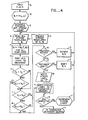
- Step A position data as a function of time are manually input, generally in the form of pairs of points x and y at sample times t (Step A).
- the string of position functions is thereafter converted to a string of vectors of precise polar values at preselected sample points along a standard stroke (Step B).
- the string of vector values is then separated into sets, each set representing a stroke.
- a stroke counter may be set to keep track of the number of strokes in a character (Step C).
- Stroke templates have been preset in the form of a string of vector values T i and deviation values ⁇ i (Step D).
- Step E All stroke templates are then read (Step E), and the distance metrics for all templates with respect to a particular stroke under examination are calculated (Step F). Thereafter, the distance metrics are sorted in order from least to greatest (Step G). The least distance metric corresponds to the most likely candidate label for the stroke under examination. However, recognition criteria are applied according to the invention to enhance the likelihood of. accurate recognition.
- the least distance metric is compared with the lower decision threshold (Step H). If the indication is that the least distance metric D i is less than the lower decision threshold, D the next least distance metric D i+1 is compared with the upper decision threshold D to see if the next least distance metric D i+1 exceeds the upper decision threshold D (Step J).
- Step K If the indication is positive, then the system writes the stroke label corresponding to the least distance metric to the character memory indicating acceptance and thus recognition of the stroke (Step K). If the indication of either of the previous threshold level tests is negative, an alternative decision process is applied. First, the least distance metric D i is compared with the upper decision threshold DU to see if the metric Di is less (Step L). If yes, then the next least distance metric D i+1 is compared with the difference decision threshold D to see if the threshold D is exceeded. The difference decision threshold D D is the sum of the least distance metric D i and the preselected separation D d (Step M). If the indication is positive, then the system indicates that it has recognized the stroke (Step K).
- Steps N,O and P,Q the system implements shift and/or rotate processing to realign the data or to rotate the values of the data.
- Steps N,O and P,Q The steps are repeated from the read in of the templates (Step E) until a decision is made. If none of the decision threshold criteria are met, the system ultimately writes the identity label as a question mark (Step R), and then the system goes to the next stroke. If the stroke is not the last stroke (Step S), then the stroke count is incremented (Step T) and the process is repeated for the next stroke. If the stroke is the last stroke, then the system conducts the character dictionary search (Step U) to identify the character.. (In some embodiments, the dictionary search may be instituted before stroke labeling is completed.)
- FIG. 6 an alternative handwritten character recognition system 110 is shown which is similar to the system 10 of Figure 1. Identical elements are designated by the same numerals.
- the data processing means 16 includes means for comparing the first signal information with second signal information independent of stroke position and further independent of stroke size to obtain an identification of the stroke under examination. Only the curvature characteristics of the stroke under examination are specified, and generally to a relatively high degree of accuracy, for use in identifying and labeling the stroke. A limited amount of position information about each stroke may be stored in a stroke position memory 102 for possible later use after the identity label has been assigned to the stroke under examination.
- the processing means 16 includes a stroke processor 26, a stroke template memory 28, a character processor 30. and a character dictionary memory 32.
- the stroke template memory 28 is responsive to a signal on a template address select line 34 to provide second signals on a second signal line 18 specifying a template address to the stroke processor 26.
- the stroke processor 26 identifies the stroke represented by the first signal information based on the second signal information.
- the first signal information applied to the stroke-process 36 may be stripped of information regarding stroke position relative to related strokes, since relative stroke position plays no part of the initial stroke recognition process.
- An identity label signal is provided at the output of the stroke processor 26 by a stroke label line 36 to the character processor 30.
- the character dictionary memory 32 is responsive to a signal on a character address select line 33 to provide signals on a character label line 31 to the character processor 30.
- the character processor 30 identifies characters as represented by a collection of identity label signals. When a single character has been identified and accepted, a character label signal is provided at the output of the character processor 30 on the third signal line 20.
- a graphic translator 22 converts the character label signals to a display signal and the output device 24 displays or presents the character. In the event more than one character is found to match the set of identity label signals employed to search the character dictionary, all are displayed and a stroke registration device 12 may then be used by an operator to indicate which of the displayed characters is to be accepted as the intended character. Upon receipt of such an identification or upon default, the intended character is then registered or otherwise used in a data processing sequence.
- a stroke position resolver 104 may be provided - which generally operates under control of the character processor 30 to receive selected information regarding positions of strokes relative to one another from stroke position memory 102 through data line 106 upon a signal through address line 108.
- the stroke position resolver is operative to receive selected relative stroke position information about tentatively identified characters from a stroke position template memory 110 through data line 112 upon receipt of a signal through address line 114.
- the template memory 110 contains a limited amount of information about relative positions of selected strokes of characters which are likely to be confused, such as relative position of key points in a reference plane.
- Data and control lines 116, 118 from the character processor 30 activate the stroke position resolver 104 to produce a character identity label through output line 120.
- Information regarding stroke position may be extracted from the stroke processor 26 prior to stroke processing and provided to the stroke position memory 102 through an input line 103.
- the stroke registration device 12 is responsive to handwritten input by means of a writing implement 38.
- Step A position data as a function of time are manually input, generally in the form of pairs of points x and y at sample times t (Step A).
- Step A-1 positional information for possible later use
- Step B the conversion of the string of position functions to a string of angular values at preselected sample points along a standard stroke, without reference to position
- Step C The string of vector values is then separated into sets, each set representing a stroke.
- a stroke counter may be set to keep track of the number of strokes in a character (Step C).
- Stroke templates have been provided in the form of a string of polar coordinate angular values T i and deviation values ⁇ i (Step D). All stroke templates are then read (Step E), and the distance metrics for all templates with respect to a particular stroke under examination are calculated (Step F). Thereafter, the distance metrics are sorted in order from least to greatest (Step G). The least distance metric corresponds to the most likely candidate for the recognized stroke. However, recognition criteria are applied according to the invention to enhance the likelihood of accurate recognition. First, the least distance metric is compared with the lower decision threshold (Step H).
- Step J If the indication is that the least distance metric D I is less than the lower decision threshold, D L , then the next least distance metric D i+1 is compared with the upper decision threshold D U to see if the next least distance metric D i+1 exceeds the upper decision threshold D U (Step J). If the indication is positive, then the system writes the identity label to the character memory indicating recognition of the stroke (Step K). If the indication of either of the previous threshold level tests is negative, an alternative decision process is applied. First, the least distance metric D i is compared with the upper decision threshold D U to see if D i is less than D U (Step L). If yes, then the next least distance metric D i+1 is compared with the difference decision threshold D to see if the threshold D is exceeded. The difference decision threshold D is the sum of the least distance metric D i and the preselected separation D d (Step M). If the indication is positive, then the system indicates that it has recognized the stroke (Step K).
- Step E the system activates the shift and/or rotate processors to realign the data or to rotate the values of the data.
- the steps are repeated from the read in of the templates (Step E) until a decision is made. If the decision threshold criteria are not met, the system writes the stroke label as a question mark (Step R), and then the system goes to the next stroke. If the stroke is not the last stroke (Step S), then the stroke count is incremented (Step T) and the process is repeated for the next stroke. If the stroke is the last stroke, then the system conducts the character dictionary search (Step U) to identify the character. The character dictionary search is conducted as described above.
- the dictionary search is an element of the algorithmic part of the processing in the forward direction (one embodiment of the invention). During a dictionary search, a significant number of dictionary entries are designated as potentially representative of the input character. The non-algorithmic routines are then applied to the designated entries to disambiguate and thus identify the input character with a single character designation in the vocabulary.
- Figures 8, 9, and 10 illustrate three patterns which correspond to dictionary entries which may be confused during a dictionary search.
- Figure 8 is a first pattern 200 corresponding to a particular nineteen-stroke version of a pattern corresponding to the JIS-1 character (24,60). It is assumed that this pattern is input by the writer.
- the illustrated nineteen-stroke version of JIS-1 character (34,01) 202 ( Figure 9) and the illustrated nineteen-stroke version of JIS-1 character (44,86) 204 ( Figure 10.). would generally also be designated as belonging to the same confusion set as the pattern 200 .
- a small confusion set has been chosen for ease of illustration.
- the basis of this confusion set may be seen by comparing the first few strokes in the stroke string.
- the first stroke of each pattern 200, 202 and 204 is generally vertical, and the coding (not shown) for the first stroke is sufficiently loose to accept a generally vertical pattern.
- the second stroke is shaped as a combination of a top horizontal and a right side vertical segment of indefinite length.
- the third stroke is generally horizontal with an accepted angular range.
- the fourth stroke is instructive.
- the fourth stroke is a particular type of vertical stroke and the allowed coding includes a vertical stroke.
- the fourth stroke is horizon-. tal. However, it is coded to also accept a vertical stroke pattern at this position because it is so short.
- the fourth stroke is a true vertical and is so coded. As much looseness as is necessary to accomodate natural writing can thus be built into the coding for the dictionary.
- the nonalgorithmic processes are applied to selected elements of each designated entry.
- corresponding disambiguation routines are applied to compare relative positions of strokes, groups of strokes, or radicals, or of any positions within a stroke or strokes.
- Other disambiguation routines may measure for example contour length, intercepts, or level of stroke complexity.
- every disambiguation routine associated with at least one entry representative of the character must produce a true indication and at least one disambiguation routine associated with each other entry in the confusion set must produce a false indication .
Landscapes
- Engineering & Computer Science (AREA)
- Computer Vision & Pattern Recognition (AREA)
- Physics & Mathematics (AREA)
- General Physics & Mathematics (AREA)
- Multimedia (AREA)
- Theoretical Computer Science (AREA)
- Character Discrimination (AREA)
Applications Claiming Priority (2)
| Application Number | Priority Date | Filing Date | Title |
|---|---|---|---|
| US53130583A | 1983-09-09 | 1983-09-09 | |
| US531305 | 1983-09-09 |
Publications (2)
| Publication Number | Publication Date |
|---|---|
| EP0135615A2 true EP0135615A2 (de) | 1985-04-03 |
| EP0135615A3 EP0135615A3 (de) | 1987-03-25 |
Family
ID=24117099
Family Applications (1)
| Application Number | Title | Priority Date | Filing Date |
|---|---|---|---|
| EP83111969A Ceased EP0135615A3 (de) | 1983-09-09 | 1983-11-29 | Verfahren und Vorrichtung hinsichtlich Mustererkennung |
Country Status (2)
| Country | Link |
|---|---|
| EP (1) | EP0135615A3 (de) |
| KR (1) | KR890002582B1 (de) |
Cited By (3)
| Publication number | Priority date | Publication date | Assignee | Title |
|---|---|---|---|---|
| US6366697B1 (en) | 1993-10-06 | 2002-04-02 | Xerox Corporation | Rotationally desensitized unistroke handwriting recognition |
| US6493464B1 (en) | 1994-07-01 | 2002-12-10 | Palm, Inc. | Multiple pen stroke character set and handwriting recognition system with immediate response |
| US6567549B1 (en) | 1996-12-05 | 2003-05-20 | Palmsource Inc. | Method and apparatus for immediate response handwriting recognition system that handles multiple character sets |
Family Cites Families (4)
| Publication number | Priority date | Publication date | Assignee | Title |
|---|---|---|---|---|
| US3182290A (en) * | 1960-10-20 | 1965-05-04 | Control Data Corp | Character reading system with sub matrix |
| JPS5136141B2 (de) * | 1971-11-10 | 1976-10-06 | ||
| JPS5517988B2 (de) * | 1974-06-05 | 1980-05-15 | ||
| JPS51118333A (en) * | 1975-04-11 | 1976-10-18 | Hitachi Ltd | Pattern recognition system |
-
1983
- 1983-11-29 EP EP83111969A patent/EP0135615A3/de not_active Ceased
- 1983-12-23 KR KR1019830006155A patent/KR890002582B1/ko not_active Expired
Cited By (4)
| Publication number | Priority date | Publication date | Assignee | Title |
|---|---|---|---|---|
| US6366697B1 (en) | 1993-10-06 | 2002-04-02 | Xerox Corporation | Rotationally desensitized unistroke handwriting recognition |
| US6816859B2 (en) | 1993-10-06 | 2004-11-09 | Xerox Corporation | Rotationally desensitized unistroke handwriting recognition |
| US6493464B1 (en) | 1994-07-01 | 2002-12-10 | Palm, Inc. | Multiple pen stroke character set and handwriting recognition system with immediate response |
| US6567549B1 (en) | 1996-12-05 | 2003-05-20 | Palmsource Inc. | Method and apparatus for immediate response handwriting recognition system that handles multiple character sets |
Also Published As
| Publication number | Publication date |
|---|---|
| EP0135615A3 (de) | 1987-03-25 |
| KR890002582B1 (ko) | 1989-07-19 |
| KR850003609A (ko) | 1985-06-20 |
Similar Documents
| Publication | Publication Date | Title |
|---|---|---|
| US4718102A (en) | Process and apparatus involving pattern recognition | |
| EP0114248B1 (de) | Verfahren und Anlage zur Erkennung komplexer Muster | |
| CA2105494C (en) | Method and apparatus for recognizing cursive writing from sequential input information | |
| US4573196A (en) | Confusion grouping of strokes in pattern recognition method and system | |
| KR100297482B1 (ko) | 수기입력의문자인식방법및장치 | |
| US6956969B2 (en) | Methods and apparatuses for handwriting recognition | |
| Wakahara et al. | On-line handwriting recognition | |
| EP0581529A2 (de) | Verfahren zum Normalisieren handgeschriebener Symbole | |
| US5659633A (en) | Character recognition method utilizing compass directions and torsion points as features | |
| EP0135615A2 (de) | Verfahren und Vorrichtung hinsichtlich Mustererkennung | |
| EP0567836A2 (de) | Schreibstilermittlung und automatische Prototypenherstellung für On-Line-Handschrifterkennung | |
| KR960001102B1 (ko) | 수서인식 시스템에서의 케이스 혼동을 해결하는 방법 | |
| Rao | A knowledge-based approach for script recognition without training | |
| CA2497586C (en) | Method and apparatus for recognizing cursive writing from sequential input information | |
| JPS60217487A (ja) | 文字認識装置 | |
| Willey | A pen-tip pressure-based system for real-time handprinted character recognition | |
| Watt | Writing on Clouds | |
| JPS6186881A (ja) | オンライン手書き文字認識方式 | |
| JPS60237581A (ja) | オンライン手書き文字認識方式 | |
| JPS636897B2 (de) | ||
| JPS60217482A (ja) | 文字認識装置 |
Legal Events
| Date | Code | Title | Description |
|---|---|---|---|
| PUAI | Public reference made under article 153(3) epc to a published international application that has entered the european phase |
Free format text: ORIGINAL CODE: 0009012 |
|
| AK | Designated contracting states |
Designated state(s): CH DE FR GB IT LI NL |
|
| PUAL | Search report despatched |
Free format text: ORIGINAL CODE: 0009013 |
|
| AK | Designated contracting states |
Kind code of ref document: A3 Designated state(s): CH DE FR GB IT LI NL |
|
| 17P | Request for examination filed |
Effective date: 19870917 |
|
| 17Q | First examination report despatched |
Effective date: 19890705 |
|
| STAA | Information on the status of an ep patent application or granted ep patent |
Free format text: STATUS: THE APPLICATION HAS BEEN REFUSED |
|
| 18R | Application refused |
Effective date: 19910117 |
|
| RIN1 | Information on inventor provided before grant (corrected) |
Inventor name: CRANE, HEWITT D. Inventor name: OSTREM, JOHN S. |