EP0135703A2 - Châssis amovible monté sur un chariot roulant sur les rails d'un monte-charge incliné - Google Patents
Châssis amovible monté sur un chariot roulant sur les rails d'un monte-charge incliné Download PDFInfo
- Publication number
- EP0135703A2 EP0135703A2 EP84108790A EP84108790A EP0135703A2 EP 0135703 A2 EP0135703 A2 EP 0135703A2 EP 84108790 A EP84108790 A EP 84108790A EP 84108790 A EP84108790 A EP 84108790A EP 0135703 A2 EP0135703 A2 EP 0135703A2
- Authority
- EP
- European Patent Office
- Prior art keywords
- support frame
- load carrier
- frame
- cross member
- longitudinal
- Prior art date
- Legal status (The legal status is an assumption and is not a legal conclusion. Google has not performed a legal analysis and makes no representation as to the accuracy of the status listed.)
- Granted
Links
Images
Classifications
-
- B—PERFORMING OPERATIONS; TRANSPORTING
- B66—HOISTING; LIFTING; HAULING
- B66B—ELEVATORS; ESCALATORS OR MOVING WALKWAYS
- B66B9/00—Kinds or types of lifts in, or associated with, buildings or other structures
- B66B9/16—Mobile or transportable lifts specially adapted to be shifted from one part of a building or other structure to another part or to another building or structure
Definitions
- the invention relates to a support frame for load carriers, such as bucket, load platform or the like, which is displaced on a slide which can be moved on rails of an inclined elevator, the support frame having at least two longitudinal supports, a front cross member and a rear cross member and the frame of the load carrier having at least two longitudinal supports and a cross member and wherein on the support frame on the one hand and on the frame of the load carrier on the other hand corresponding locking devices are provided for connecting the support frame and the frame of the load carrier.
- load carriers such as bucket, load platform or the like
- the support frame displaced on the carriage and the frame of the load carrier to be designed so that both parts can be quickly and safely connected to one another or detached from one another.
- the invention is based on the consideration that the two aforementioned frames are matched to one another with respect to their connecting means so that the frame of the load carrier can be both a frame for receiving a dumping bucket and a frame for receiving a load platform of different types.
- the connection of the two aforementioned components should be easy to handle, but it should still be easy to assemble and disassemble and ensure reliable locking of the two parts.
- the invention proposes in a support frame of the type mentioned that the locking devices between the longitudinal member or cross member of the support frame and the longitudinal member (and possibly cross member) of the frame of the load carrier are plug connections.
- These plug connections are easily detachable, and according to a special feature of the invention, two plug connections are provided at a distance from each other between a longitudinal beam of the support frame and a longitudinal beam of the frame of the load carrier.
- the insertion directions of the plug connections are arranged offset by approximately 90 ° to one another.
- This locking device can be a locking bolt directed at 90 ° to the first plug connection.
- the rear crossmember of the support frame has projections which form stub axles and protrude beyond its longitudinal members.
- These extensions forming axles are advantageously suitable, the rear, i.e. to produce the lower plug-in connection by holding claws covering the axle stub of the cross member on the longitudinal members of the frame of the load carrier.
- These holding claws can cover the stub axles of the cross member on the top and bottom; however, they can also form a limitation against displacement at least in one of the two longitudinal directions of the longitudinal beams.
- the support frame is connected in the front third of its length via an angle lever with the carriage.
- the arrangement and design of the angle lever is chosen so that to tilt the support frame in the upper bottom sition as little winch traction is required. The angle lever is therefore not supported after the hour.
- T. belonging proposal with its lower free angle leg seen in the elevator direction behind the front roller on the carriage.
- each longitudinal beam of the support frame is rotatably connected to a rotatably supported on the carriage angle lever.
- the second locking provided at a distance from the holding claws is advantageously achieved in that a locking bolt which can be connected directly or indirectly to the supporting frame is arranged on the longitudinal member of the frame of the load carrier.
- a pipe guide for the passage of the locking bolt is arranged on the longitudinal member of the frame of the load carrier, which passes through the angle lever for locking with the support frame.
- a long locking bolt is provided, which is designed as a common locking bolt for the passage of both pipe guides arranged on the two longitudinal beams of the frame of the load carrier and the angle levers arranged on the longitudinal beams of the support frame.
- the rear cross member of the support frame which is covered by the claws arranged on the frame of the load carrier, is designed as a tube with a circular cross section; this makes it easier to attach the holding claws to the tubular, protruding stub axles.
- the free ends of the side members of the support frame form extensions projecting beyond the front cross member of the support frame; this allows the respective load carrier to be conveniently shifted onto the support frame.
- the invention can advantageously be implemented both when using pouring buckets and when using load platforms; when used in connection with bulk buckets, it is proposed that the longitudinal members of the frame of the load carrier carry connection brackets for the bulk bucket provided at their rear free end.
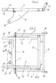
- the support frame designated 1 consists essentially of two side members 2 and 2 'and two cross members 3 and 3'. It is pivotally displaced via the angled levers 13 and 13 '(see also FIG. 2) via a bolt connection (bore 19) on the carriage, not shown, so that it moves counterclockwise when the carriage moves in the direction of arrow 20 when the end stop is reached Senses (Fig. 2) can be pivoted.
- the support frame 1 consisting of the aforementioned basic components is designed in accordance with the invention in such a way that it can be connected with little effort to a further frame 4 which connects the frame of any load carrier, in the illustrated embodiment of a pouring bucket (see connection brackets 18 and 18 'with bore 17 ) forms.
- the frame 4 of the load carrier essentially consists of two side members 5 and 5 'and a cross member 6.
- the locking device 8 consists of a holding claw 12, which can be formed by a top-side and bottom-side sheet or by a short U-profile (see FIG. 2), which is welded to the side members 5 and 5 '.
- the rear cross member 3 'of the frame 3 which is designed as a circular tube in cross section, has stub axles 11 and 11' which project laterally beyond the side members 2 and 2 '.
- the fixed to the side members 5 and 5 'of the frame 4 holding claws 12 are designed so that they can be pushed in the direction of arrow 9 on the stub axles 11 and 11' and thus secure the frame 4 of the load carrier against the support frame 1 against lifting.
- the second plug connection is made offset by 90 ° compared to the production of the first plug connection 8, i.e. the locking bolt 14 is inserted in the direction of the arrow 10.
- the locking bolt 14 first passes through a pipe guide 15, which is firmly connected by welding to the frame 4 of the load carrier, not shown.
- the locking bolt 14 further includes the angle lever 13, the second angle lever 13 'and the pipe guide 15' and is secured at 21 in a suitable manner against displacement.
- locking devices 22 and 22 ' are arranged on the front cross member 3 of the support frame, which can be actuated by means of a hand lever designated 23. These locking devices are used to determine the respective load carrier; however, they are not the subject of the above-described invention.
Landscapes
- Engineering & Computer Science (AREA)
- Structural Engineering (AREA)
- Civil Engineering (AREA)
- Transportation (AREA)
- Automation & Control Theory (AREA)
- Handcart (AREA)
- Types And Forms Of Lifts (AREA)
- Body Structure For Vehicles (AREA)
- Cage And Drive Apparatuses For Elevators (AREA)
Priority Applications (1)
| Application Number | Priority Date | Filing Date | Title |
|---|---|---|---|
| AT84108790T ATE45558T1 (de) | 1983-08-29 | 1984-07-25 | An einem an schienen eines schraegaufzuges verfahrbaren schlitten gelagerter tragrahmen. |
Applications Claiming Priority (2)
| Application Number | Priority Date | Filing Date | Title |
|---|---|---|---|
| DE19838324783U DE8324783U1 (de) | 1983-08-29 | 1983-08-29 | An einem an schienen eines schraegaufzuges verfahrbaren schlitten verlagerter tragrahmen |
| DE8324783U | 1983-08-29 |
Publications (3)
| Publication Number | Publication Date |
|---|---|
| EP0135703A2 true EP0135703A2 (fr) | 1985-04-03 |
| EP0135703A3 EP0135703A3 (en) | 1987-12-16 |
| EP0135703B1 EP0135703B1 (fr) | 1989-08-16 |
Family
ID=6756584
Family Applications (1)
| Application Number | Title | Priority Date | Filing Date |
|---|---|---|---|
| EP84108790A Expired EP0135703B1 (fr) | 1983-08-29 | 1984-07-25 | Châssis amovible monté sur un chariot roulant sur les rails d'un monte-charge incliné |
Country Status (3)
| Country | Link |
|---|---|
| EP (1) | EP0135703B1 (fr) |
| AT (1) | ATE45558T1 (fr) |
| DE (2) | DE8324783U1 (fr) |
Cited By (1)
| Publication number | Priority date | Publication date | Assignee | Title |
|---|---|---|---|---|
| US8794185B2 (en) | 2004-04-15 | 2014-08-05 | Vetech Laboratories Inc. | Soft gel delivery system for treating poultry |
Families Citing this family (1)
| Publication number | Priority date | Publication date | Assignee | Title |
|---|---|---|---|---|
| DE3517291A1 (de) * | 1985-05-14 | 1986-11-20 | Albert Böcker GmbH & Co KG, 4712 Werne | Schraegaufzug fuer den transport von lasten |
Family Cites Families (3)
| Publication number | Priority date | Publication date | Assignee | Title |
|---|---|---|---|---|
| US3666054A (en) * | 1970-02-24 | 1972-05-30 | Frank L Ellings | Ladder dolly and winch |
| GB1378318A (en) * | 1973-03-15 | 1974-12-27 | Evans P N | Material hoists |
| US3874477A (en) * | 1973-03-21 | 1975-04-01 | Ture E Hedstrom | Method and arrangement for shoring up the base frame of lifts hoists and the like |
-
1983
- 1983-08-29 DE DE19838324783U patent/DE8324783U1/de not_active Expired
-
1984
- 1984-07-25 DE DE8484108790T patent/DE3479417D1/de not_active Expired
- 1984-07-25 EP EP84108790A patent/EP0135703B1/fr not_active Expired
- 1984-07-25 AT AT84108790T patent/ATE45558T1/de not_active IP Right Cessation
Cited By (1)
| Publication number | Priority date | Publication date | Assignee | Title |
|---|---|---|---|---|
| US8794185B2 (en) | 2004-04-15 | 2014-08-05 | Vetech Laboratories Inc. | Soft gel delivery system for treating poultry |
Also Published As
| Publication number | Publication date |
|---|---|
| ATE45558T1 (de) | 1989-09-15 |
| DE8324783U1 (de) | 1983-12-15 |
| EP0135703A3 (en) | 1987-12-16 |
| EP0135703B1 (fr) | 1989-08-16 |
| DE3479417D1 (en) | 1989-09-21 |
Similar Documents
| Publication | Publication Date | Title |
|---|---|---|
| DE3330035A1 (de) | Anhaenger | |
| WO2009036750A2 (fr) | Système de transport comportant notamment des palettes mobiles | |
| EP0442956B1 (fr) | Vehicule pour poser des ponts demontables | |
| DE1194715B (de) | Vorrichtung zum Auf- und Abladen grosser, wagenkastenartiger Behaelter auf Fahrzeuge | |
| DE2334978C3 (de) | Überflur-Schleppkettenförderer | |
| DE1937845C3 (de) | Hublader | |
| DE898554C (de) | Plattformwagen fuer den Transport von Fahrzeugen | |
| DE3403845A1 (de) | Palettenhubwagen mit zur anpassung an das bodenprofil geeigneten rollorganen | |
| DE2755223A1 (de) | Einrichtung zum umsetzen von transportguetern | |
| EP0135703B1 (fr) | Châssis amovible monté sur un chariot roulant sur les rails d'un monte-charge incliné | |
| EP0564403A1 (fr) | Dispositif de chargement et de déchargement d'un porte-charges sur un véhicule | |
| DE3505506C2 (de) | Aus mehreren seilbetätigt teleskopierbaren Teleskopschüssen bestehender Schrägaufzug | |
| AT396986B (de) | Einrichtung zum beladen, entladen und transportieren eines geschützes od.dgl. | |
| DE3426985A1 (de) | An einem an schienen eines schraegaufzuges verfahrbaren schlitten verlagerter tragrahmen | |
| DE309065C (fr) | ||
| DE2523060A1 (de) | Einrichtung fuer hubschienen von schleppkreisfoerderern | |
| DE2327533B2 (de) | Mit Laufrädern versehener Ladegutträger | |
| DE3517291A1 (de) | Schraegaufzug fuer den transport von lasten | |
| DE8011609U1 (de) | Fahrzeug fuer den transport von personenkraftwagen | |
| DE2650270C2 (de) | Lastkraftfahrzeug | |
| DE1481479C (de) | Behaltertransportsystem | |
| DE2403977A1 (de) | Verfahren zum heben von lasten mit einem kran, und baukran zur durchfuehrung des verfahrens | |
| DE3049152A1 (de) | Stapelbarer, offener sammelbehaelter, insbesondere fuer bauschutt | |
| DE2137858C3 (de) | Schleppkreisförderer | |
| DE3407568A1 (de) | Wechselbehaelter-transport-system |
Legal Events
| Date | Code | Title | Description |
|---|---|---|---|
| PUAI | Public reference made under article 153(3) epc to a published international application that has entered the european phase |
Free format text: ORIGINAL CODE: 0009012 |
|
| AK | Designated contracting states |
Designated state(s): AT BE CH DE FR GB IT LI NL SE |
|
| 17P | Request for examination filed |
Effective date: 19850605 |
|
| PUAL | Search report despatched |
Free format text: ORIGINAL CODE: 0009013 |
|
| AK | Designated contracting states |
Kind code of ref document: A3 Designated state(s): AT BE CH DE FR GB IT LI NL SE |
|
| 17Q | First examination report despatched |
Effective date: 19880908 |
|
| ITF | It: translation for a ep patent filed | ||
| GRAA | (expected) grant |
Free format text: ORIGINAL CODE: 0009210 |
|
| AK | Designated contracting states |
Kind code of ref document: B1 Designated state(s): AT BE CH DE FR GB IT LI NL SE |
|
| REF | Corresponds to: |
Ref document number: 45558 Country of ref document: AT Date of ref document: 19890915 Kind code of ref document: T |
|
| REF | Corresponds to: |
Ref document number: 3479417 Country of ref document: DE Date of ref document: 19890921 |
|
| GBT | Gb: translation of ep patent filed (gb section 77(6)(a)/1977) | ||
| ET | Fr: translation filed | ||
| PLBE | No opposition filed within time limit |
Free format text: ORIGINAL CODE: 0009261 |
|
| STAA | Information on the status of an ep patent application or granted ep patent |
Free format text: STATUS: NO OPPOSITION FILED WITHIN TIME LIMIT |
|
| 26N | No opposition filed | ||
| ITTA | It: last paid annual fee | ||
| EAL | Se: european patent in force in sweden |
Ref document number: 84108790.1 |
|
| PGFP | Annual fee paid to national office [announced via postgrant information from national office to epo] |
Ref country code: SE Payment date: 19960529 Year of fee payment: 13 |
|
| PGFP | Annual fee paid to national office [announced via postgrant information from national office to epo] |
Ref country code: FR Payment date: 19960531 Year of fee payment: 13 |
|
| PGFP | Annual fee paid to national office [announced via postgrant information from national office to epo] |
Ref country code: DE Payment date: 19960610 Year of fee payment: 13 |
|
| PGFP | Annual fee paid to national office [announced via postgrant information from national office to epo] |
Ref country code: GB Payment date: 19960715 Year of fee payment: 13 |
|
| PGFP | Annual fee paid to national office [announced via postgrant information from national office to epo] |
Ref country code: BE Payment date: 19960725 Year of fee payment: 13 Ref country code: AT Payment date: 19960725 Year of fee payment: 13 |
|
| PGFP | Annual fee paid to national office [announced via postgrant information from national office to epo] |
Ref country code: NL Payment date: 19960731 Year of fee payment: 13 |
|
| PGFP | Annual fee paid to national office [announced via postgrant information from national office to epo] |
Ref country code: CH Payment date: 19961031 Year of fee payment: 13 |
|
| PG25 | Lapsed in a contracting state [announced via postgrant information from national office to epo] |
Ref country code: GB Free format text: LAPSE BECAUSE OF NON-PAYMENT OF DUE FEES Effective date: 19970725 Ref country code: AT Free format text: LAPSE BECAUSE OF NON-PAYMENT OF DUE FEES Effective date: 19970725 |
|
| PG25 | Lapsed in a contracting state [announced via postgrant information from national office to epo] |
Ref country code: SE Effective date: 19970726 |
|
| PG25 | Lapsed in a contracting state [announced via postgrant information from national office to epo] |
Ref country code: LI Free format text: LAPSE BECAUSE OF NON-PAYMENT OF DUE FEES Effective date: 19970731 Ref country code: CH Free format text: LAPSE BECAUSE OF NON-PAYMENT OF DUE FEES Effective date: 19970731 Ref country code: BE Free format text: LAPSE BECAUSE OF NON-PAYMENT OF DUE FEES Effective date: 19970731 |
|
| BERE | Be: lapsed |
Owner name: ALBERT BOCKER G.M.B.H. & CO. K.G. Effective date: 19970731 |
|
| PG25 | Lapsed in a contracting state [announced via postgrant information from national office to epo] |
Ref country code: NL Free format text: LAPSE BECAUSE OF NON-PAYMENT OF DUE FEES Effective date: 19980201 |
|
| REG | Reference to a national code |
Ref country code: CH Ref legal event code: PL |
|
| GBPC | Gb: european patent ceased through non-payment of renewal fee |
Effective date: 19970725 |
|
| PG25 | Lapsed in a contracting state [announced via postgrant information from national office to epo] |
Ref country code: FR Free format text: LAPSE BECAUSE OF NON-PAYMENT OF DUE FEES Effective date: 19980331 |
|
| NLV4 | Nl: lapsed or anulled due to non-payment of the annual fee |
Effective date: 19980201 |
|
| PG25 | Lapsed in a contracting state [announced via postgrant information from national office to epo] |
Ref country code: DE Free format text: LAPSE BECAUSE OF NON-PAYMENT OF DUE FEES Effective date: 19980401 |
|
| EUG | Se: european patent has lapsed |
Ref document number: 84108790.1 |
|
| REG | Reference to a national code |
Ref country code: FR Ref legal event code: ST |