EP0135849A2 - Maschine zum Bohren von zerbrechlichen plattenförmigen Materialien, insbesondere Flachglas und dgl. - Google Patents
Maschine zum Bohren von zerbrechlichen plattenförmigen Materialien, insbesondere Flachglas und dgl. Download PDFInfo
- Publication number
- EP0135849A2 EP0135849A2 EP84110440A EP84110440A EP0135849A2 EP 0135849 A2 EP0135849 A2 EP 0135849A2 EP 84110440 A EP84110440 A EP 84110440A EP 84110440 A EP84110440 A EP 84110440A EP 0135849 A2 EP0135849 A2 EP 0135849A2
- Authority
- EP
- European Patent Office
- Prior art keywords
- sheet blank
- sheet
- drilling
- frame
- machine according
- Prior art date
- Legal status (The legal status is an assumption and is not a legal conclusion. Google has not performed a legal analysis and makes no representation as to the accuracy of the status listed.)
- Granted
Links
Images
Classifications
-
- B—PERFORMING OPERATIONS; TRANSPORTING
- B65—CONVEYING; PACKING; STORING; HANDLING THIN OR FILAMENTARY MATERIAL
- B65G—TRANSPORT OR STORAGE DEVICES, e.g. CONVEYORS FOR LOADING OR TIPPING, SHOP CONVEYOR SYSTEMS OR PNEUMATIC TUBE CONVEYORS
- B65G49/00—Conveying systems characterised by their application for specified purposes not otherwise provided for
- B65G49/05—Conveying systems characterised by their application for specified purposes not otherwise provided for for fragile or damageable materials or articles
- B65G49/06—Conveying systems characterised by their application for specified purposes not otherwise provided for for fragile or damageable materials or articles for fragile sheets, e.g. glass
- B65G49/067—Sheet handling, means, e.g. manipulators, devices for turning or tilting sheet glass
-
- B—PERFORMING OPERATIONS; TRANSPORTING
- B23—MACHINE TOOLS; METAL-WORKING NOT OTHERWISE PROVIDED FOR
- B23B—TURNING; BORING
- B23B39/00—General-purpose boring or drilling machines or devices; Sets of boring and/or drilling machines
- B23B39/003—Drilling machine situated underneath the workpiece
-
- B—PERFORMING OPERATIONS; TRANSPORTING
- B23—MACHINE TOOLS; METAL-WORKING NOT OTHERWISE PROVIDED FOR
- B23B—TURNING; BORING
- B23B39/00—General-purpose boring or drilling machines or devices; Sets of boring and/or drilling machines
- B23B39/16—Drilling machines with a plurality of working-spindles; Drilling automatons
- B23B39/22—Drilling machines with a plurality of working-spindles; Drilling automatons with working-spindles in opposite headstocks
-
- B—PERFORMING OPERATIONS; TRANSPORTING
- B23—MACHINE TOOLS; METAL-WORKING NOT OTHERWISE PROVIDED FOR
- B23B—TURNING; BORING
- B23B41/00—Boring or drilling machines or devices specially adapted for particular work; Accessories specially adapted therefor
- B23B41/003—Boring or drilling machines or devices specially adapted for particular work; Accessories specially adapted therefor for drilling elongated pieces, e.g. beams
-
- B—PERFORMING OPERATIONS; TRANSPORTING
- B23—MACHINE TOOLS; METAL-WORKING NOT OTHERWISE PROVIDED FOR
- B23Q—DETAILS, COMPONENTS, OR ACCESSORIES FOR MACHINE TOOLS, e.g. ARRANGEMENTS FOR COPYING OR CONTROLLING; MACHINE TOOLS IN GENERAL CHARACTERISED BY THE CONSTRUCTION OF PARTICULAR DETAILS OR COMPONENTS; COMBINATIONS OR ASSOCIATIONS OF METAL-WORKING MACHINES, NOT DIRECTED TO A PARTICULAR RESULT
- B23Q7/00—Arrangements for handling work specially combined with or arranged in, or specially adapted for use in connection with, machine tools, e.g. for conveying, loading, positioning, discharging, sorting
- B23Q7/04—Arrangements for handling work specially combined with or arranged in, or specially adapted for use in connection with, machine tools, e.g. for conveying, loading, positioning, discharging, sorting by means of grippers
- B23Q7/041—Arrangements for handling work specially combined with or arranged in, or specially adapted for use in connection with, machine tools, e.g. for conveying, loading, positioning, discharging, sorting by means of grippers step by step
-
- B—PERFORMING OPERATIONS; TRANSPORTING
- B23—MACHINE TOOLS; METAL-WORKING NOT OTHERWISE PROVIDED FOR
- B23Q—DETAILS, COMPONENTS, OR ACCESSORIES FOR MACHINE TOOLS, e.g. ARRANGEMENTS FOR COPYING OR CONTROLLING; MACHINE TOOLS IN GENERAL CHARACTERISED BY THE CONSTRUCTION OF PARTICULAR DETAILS OR COMPONENTS; COMBINATIONS OR ASSOCIATIONS OF METAL-WORKING MACHINES, NOT DIRECTED TO A PARTICULAR RESULT
- B23Q7/00—Arrangements for handling work specially combined with or arranged in, or specially adapted for use in connection with, machine tools, e.g. for conveying, loading, positioning, discharging, sorting
- B23Q7/05—Arrangements for handling work specially combined with or arranged in, or specially adapted for use in connection with, machine tools, e.g. for conveying, loading, positioning, discharging, sorting by means of roller-ways
- B23Q7/055—Arrangements for handling work specially combined with or arranged in, or specially adapted for use in connection with, machine tools, e.g. for conveying, loading, positioning, discharging, sorting by means of roller-ways some of the rollers being driven
-
- B—PERFORMING OPERATIONS; TRANSPORTING
- B28—WORKING CEMENT, CLAY, OR STONE
- B28D—WORKING STONE OR STONE-LIKE MATERIALS
- B28D1/00—Working stone or stone-like materials, e.g. brick, concrete or glass, not provided for elsewhere; Machines, devices, tools therefor
- B28D1/14—Working stone or stone-like materials, e.g. brick, concrete or glass, not provided for elsewhere; Machines, devices, tools therefor by boring or drilling
-
- B—PERFORMING OPERATIONS; TRANSPORTING
- B28—WORKING CEMENT, CLAY, OR STONE
- B28D—WORKING STONE OR STONE-LIKE MATERIALS
- B28D7/00—Accessories specially adapted for use with machines or devices of the preceding groups
- B28D7/04—Accessories specially adapted for use with machines or devices of the preceding groups for supporting or holding work or conveying or discharging work
-
- B—PERFORMING OPERATIONS; TRANSPORTING
- B23—MACHINE TOOLS; METAL-WORKING NOT OTHERWISE PROVIDED FOR
- B23B—TURNING; BORING
- B23B2220/00—Details of turning, boring or drilling processes
- B23B2220/32—Drilling holes from both sides
-
- B—PERFORMING OPERATIONS; TRANSPORTING
- B23—MACHINE TOOLS; METAL-WORKING NOT OTHERWISE PROVIDED FOR
- B23B—TURNING; BORING
- B23B2226/00—Materials of tools or workpieces not comprising a metal
- B23B2226/45—Glass
-
- Y—GENERAL TAGGING OF NEW TECHNOLOGICAL DEVELOPMENTS; GENERAL TAGGING OF CROSS-SECTIONAL TECHNOLOGIES SPANNING OVER SEVERAL SECTIONS OF THE IPC; TECHNICAL SUBJECTS COVERED BY FORMER USPC CROSS-REFERENCE ART COLLECTIONS [XRACs] AND DIGESTS
- Y10—TECHNICAL SUBJECTS COVERED BY FORMER USPC
- Y10T—TECHNICAL SUBJECTS COVERED BY FORMER US CLASSIFICATION
- Y10T408/00—Cutting by use of rotating axially moving tool
- Y10T408/36—Machine including plural tools
- Y10T408/375—Coaxial tools
- Y10T408/378—Coaxial, opposed tools
- Y10T408/3788—Plural pairs of coaxial, opposed tools
-
- Y—GENERAL TAGGING OF NEW TECHNOLOGICAL DEVELOPMENTS; GENERAL TAGGING OF CROSS-SECTIONAL TECHNOLOGIES SPANNING OVER SEVERAL SECTIONS OF THE IPC; TECHNICAL SUBJECTS COVERED BY FORMER USPC CROSS-REFERENCE ART COLLECTIONS [XRACs] AND DIGESTS
- Y10—TECHNICAL SUBJECTS COVERED BY FORMER USPC
- Y10T—TECHNICAL SUBJECTS COVERED BY FORMER US CLASSIFICATION
- Y10T408/00—Cutting by use of rotating axially moving tool
- Y10T408/44—Cutting by use of rotating axially moving tool with means to apply transient, fluent medium to work or product
- Y10T408/46—Cutting by use of rotating axially moving tool with means to apply transient, fluent medium to work or product including nozzle
-
- Y—GENERAL TAGGING OF NEW TECHNOLOGICAL DEVELOPMENTS; GENERAL TAGGING OF CROSS-SECTIONAL TECHNOLOGIES SPANNING OVER SEVERAL SECTIONS OF THE IPC; TECHNICAL SUBJECTS COVERED BY FORMER USPC CROSS-REFERENCE ART COLLECTIONS [XRACs] AND DIGESTS
- Y10—TECHNICAL SUBJECTS COVERED BY FORMER USPC
- Y10T—TECHNICAL SUBJECTS COVERED BY FORMER US CLASSIFICATION
- Y10T408/00—Cutting by use of rotating axially moving tool
- Y10T408/47—Cutting by use of rotating axially moving tool with work-infeed means
-
- Y—GENERAL TAGGING OF NEW TECHNOLOGICAL DEVELOPMENTS; GENERAL TAGGING OF CROSS-SECTIONAL TECHNOLOGIES SPANNING OVER SEVERAL SECTIONS OF THE IPC; TECHNICAL SUBJECTS COVERED BY FORMER USPC CROSS-REFERENCE ART COLLECTIONS [XRACs] AND DIGESTS
- Y10—TECHNICAL SUBJECTS COVERED BY FORMER USPC
- Y10T—TECHNICAL SUBJECTS COVERED BY FORMER US CLASSIFICATION
- Y10T408/00—Cutting by use of rotating axially moving tool
- Y10T408/55—Cutting by use of rotating axially moving tool with work-engaging structure other than Tool or tool-support
- Y10T408/561—Having tool-opposing, work-engaging surface
- Y10T408/5623—Having tool-opposing, work-engaging surface with presser foot
-
- Y—GENERAL TAGGING OF NEW TECHNOLOGICAL DEVELOPMENTS; GENERAL TAGGING OF CROSS-SECTIONAL TECHNOLOGIES SPANNING OVER SEVERAL SECTIONS OF THE IPC; TECHNICAL SUBJECTS COVERED BY FORMER USPC CROSS-REFERENCE ART COLLECTIONS [XRACs] AND DIGESTS
- Y10—TECHNICAL SUBJECTS COVERED BY FORMER USPC
- Y10T—TECHNICAL SUBJECTS COVERED BY FORMER US CLASSIFICATION
- Y10T83/00—Cutting
- Y10T83/647—With means to convey work relative to tool station
- Y10T83/6539—With means for transverse positioning of work on a moving conveyor
Definitions
- This invention relates to a machine for drilling fragile sheet-like materials, in particular sheet glass and the like.
- a sheet or plate blank is located by means of a set of detents arranged to abut against the peripheral edge of the blank; the detents can be registered in position according to the size of the blank and locations of the holes to be drilled.
- drill heads of the diamond mill type are utilized which are cooled by a continuous stream of water effective to remove the heat generated by the milling action as well as the glass chips being produced.
- This working environment also affects the machine life, and in particular its electric motors, since in severe service conditions,such as are imposed by an environment rich in moisture and glass chips, they are apt to be subjected to a faster wear rate and consequent rapid deterioration thereof.
- a further object of the invention is to provide a machine as indicated, which can be readily incorporated to processing lines and has provisions for NO operation.
- a machine for drilling fragile sheet-like materials in particular sheet glass and the like, of a type comprising a feed-in station for a sheet blank arranged to cooperate with a sheet blank drilling station, said feed-in station including a frame, a means of moving said sheet blank slidingly on said frame, and a position reference means for said sheet blank, said sheet blank drilling station including a frame provided with a holding and locating means for drill units overlying and underlying a working zone and adapted to interact with said sheet blank at said working zone, characterized in that said slide means comprises a plurality of rollers at least some whereof are driven by a motor unit and provided with a means of combining a forward movement of said sheet blank with an approaching movement of said sheet blank toward an abutment member connected to said frame.
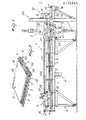
- a machine comprises essentially a feed-in station 1 for a sheet-like or plate-like material of the type shown in Figure 3 and indicated at 3, which station is arranged to cooperate with a drilling station 2 provided in line with the former station.
- the feed-in station includes essentially a frame 4 on which a means of slidingly moving the sheet blank 3 are disposed,which comprises a plurality of rollers 5 mounted rotatably on the frame and at least some of which are subjected to the drive from a motor unit 6 through a kinematic transmission means 7.
- rollers form a surface or deck whereon the sheet blank 3 can be advanced, and are preferably laid with their axes crosswise relatively to the sheet blanks' direction of advancement, as indicated by the arrow A in Figure 3.
- a peripherally mounted shroud 8 having a plurality of ridges 9 which extend helically around the rotation axis of each roller so that the rotational drive imparted thereto results in a combined motion of the sheet blank toward the drilling station and concurrently closer to an abutment 10 connected to the frame.
- a carriage 11 mounted to run along runways 12a and 12b laterally associated with the frame 4 whereon a number of gripper assemblies 13 are placed which provide a gripping action as well as a drive action to advance the sheet blank during the drilling operations.
- the carriage is driven through a first screw transmission of the so called ball recirculating type 14 controlled via a first transducer 15 of the type usually employed for detecting angular positions and actuated by means of an actuator 16 carried on the frame.
- Each gripper assembly has a gripping head 17 formed by first and second jaws 18 and ,19, respectively, which are separately connected to respective fluid dynamic actuators and adapted to grip the edge of the sheet blank 3.
- the second jaw is movable, as the carriage is being moved forward with a blank held in the gripper assembly, within annular grooves 20 formed in the roller shroud.
- the positional detent means comprises, on the drilling station side, a pad element 21, such as in the form of a movable rod relatively to the frame in a substantially vertical direction to the direction of advance A of the blank being fed to the cited station; preferably, the pad element is formed from a soft material to avoid chipping the sheet edge as the same is caused to bear on it under the urge from the rollers.
- a fluid dynamic actuator 22 associated with the frame and adapted to feed the pad element into a position of interference with the sheet blank as the same is being moved forward and simultaneously encouraged to slide against the abutment by the rollers, to be then retracted into a position of non-interference with the feed-in surface as the blank, gripped in the gripper assemblies, is moved on toward the drilling station.
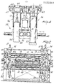
- the drilling station essentially includes a frame 30, preferably independent of the frame of the station 1, on which supporting and locating means for the drill units, respectively designated with the reference numerals 31a and 31b, are mounted; the drill unit 31a essentially comprises an upper drilling head 32 facing a lower drilling head 33 in aligned relationship therewith, while the drill unit 31b preferably comprises a pair of upper drilling heads 34 in the same conditions of alignment and superimposition on a pair of lower drilling heads 35.
- each drill unit to be provided with tool bits having different size and functional characteristics, thereby allowing differently configured holes to be made through the sheet blank 3 without manual intervention to replace the tool bits.
- the upper drilling heads 32 and 34 are associated with an upper grooved bar 36 in sliding and kinematic engagement therewith; furthermore, the head 32 and pair of heads 34 respectively engage with second and third screw transmissions of the so called ball recireu- lating type indicated at 38 and 39, respectively; provided on the frame for like functions are a lower grooved bar 40 and third and fourth screw transmissions of the so called ball recirculating type 41 and 42, respectively, engaging with the drilling head 33 and head pair 35.
- the cited screw transmission means and grooved bars form drill unit supporting and locating means, and respectively overlie and underlie a working zone of said units at a position corresponding to an extension of the sheet blank feeding surface, thereby each drill unit is adapted to interact with the sheet blank at said working zone.
- the screw transmissions of the so called ball recirculating type 38 and 41 cooperate, through a kinematic drive 43, with a first motor 44 provided for translating and positioning the drill unit 31a; likewise, the remaining cited screw transmissions 39 and 42 are kinematically connected to a second motor 45 acting, through a second kinematic drive 46, on those same screw transmissions.
- each drill unit on at least one of the cited screw transmissions, is an angular detector 48 of the type specified above, adapted to detect the position of the carriage 11 on the runways 12a and 12b.
- the grooved bars 36 and 40 cooperate, in turn, with first and second step motors 49 and 50, respectively, which by turning their respective bars drive the drilling heads upwards and downwards along with their tool bits 51 relatively to the working zone.
- the grooved bar 40 is arranged to cooperate, through a kinematic drive 52, with racks 53 provided on each drilling head and generally indicated at 54 and 55, respectively, such that, with the head 54 raised by the drive from the bar 40, the corresponding head 55 is lowered from the working zone.
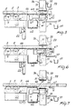
- each drilling head cooperates with a pressure member 56 mounted slidably on a corresponding head and being driven, through the action of fluid dynamic actuators 57 t ,into engagement with the sheet blank during the drilling operation in order to prevent imposing bending or vibrational stresses thereon as due to the action of the tool bits 51.
- Each drilling head is hydraulically connected, via a rotary distributor 57, to a cooling fluid supply, not shown, which fluid is delivered through the drilling head to the tool bit for cooling and removing the chips produced thereby.
- This device usually incorporated to conventional machines, involves a whole series of problems which are obviated by the invention by associating with each pressure member a discharge conduit 58 cooperating with a trough 59 adapted to convey the cooling fluid and glass chips admixed to it toward a dumping area remote from the working zone.
- the pressure member by engaging the sheet blank through a ring nut 60, avoids spilling the cooling fluid and picks it up to convey it to the discharge conduit 58.
- the lower heads have also a puller chest indicated at 61 associated therewith and cooperating with a collecting chest 62.
- the chest 61 can be snap moved by means of a fluid dynamic cylinder 63 acting in a substantially orthogonal direction to the boring axis, and is moved from a first position whereat a collecting hole 64 thereof underlies the corresponding upper drilling head to a second position, whereat its discharge hole 65 is brought into alignment with the chest 62.
- the feed-in station preferably comprises a plurality of idle rollers 66 having their axes arranged substantially parallel to those of said rollers and being adapted to avoid leaving an excessively long section of the sheet blank unsupported.
- An additional roller 67 is provided downstream of the drilling heads in the sheet blank feeding direction and has similar features to said idle rollers.
- a further advantageous feature of the machine of this invention is that a glass sheet can also be processed along its edge gripped in the members 17; these are, in fact, so sized and disposed as to be able to move into the working zone to set up the sheet.
- This particular processing method requires the availability of some holding means, generally indicated herein at 70, associated with the frame 30.
- Such holding means comprises preferably a cylinder actuator 71 carried on the frame with the intermediary of brackets 72 and being provided, on the sheet blank side thereof, with a pressure element 73 extending crosswise to the sheet blank direction of movement and cooperating with discharge rollers 74 which are carried on a supporting framework 75 and possibly driven positively off a drive arrangement 76.
- a sheet blank to be processed is fed to the station 1 in the direction of the arrow A.
- the kinematic drive acting on the latter causes, by driving said rollers, the sheet blank to move forward, this forward movement combining itself, through the ridges provided on the shroud of each roller, with a translatory movement thereof toward the abutment 10.
- Said zero position is specially useful where the machine is associated with an NO control because it provides a fixed reference relatively to which the traverse coordinates for the drilling heads can be programmed.
- the sheet blank is moved forward to bear on the pad 21 which, together with the abutment detent, is a part of the positional detent means.
- rollers are brought to a stop, and the carriage 11 moves forward to take the gripper head to engage with the trailing edge of the sheet blank.
- the carriage is moved forward by the rotary action of the screw transmission of the so called ball recirculating type 14, which action would be controlled through the first transducer 15.
- the jaws 18 and 19 will grip it and the pad 21 be retracted to a position of non-interference with the sheet blank feeding surface.
- the drill units will be positioned preparatory to drilling through the sheet blank.
- the carriage has been moved forward by a sufficient distance to permit two-dimensional centering of a hole to be drilled.
- the pressure members of the drill unit selected are brought to engage the sheet blank such that the corresponding ring nuts will adhere on opposed surfaces thereof; thereafter, the lower head will drill through the sheet blank to a depth equal to one half its dimensional thickness and be withdrawn as soon as the desired depth is reached. This depth would be programmed through the step motors 49 and 50 according to the selected head.
- the corresponding upper head is engaged with the sheet blank and cut off, by milling along an annulus through the remaining depth, the small cylindrical off cut, or carrot is dropped into the chest 61.
- the chest will be withdrawn with a snap movement to cause the carrot to drop into the chest 62, from which it may later be removed on the occasion of some maintenance and/or cleaning operations.
- the coolant is not spread all over the sheet blank to result in an inconvenient working area for the operator, but is collected within the pressure member and directed, through the discharge 58, into the collecting pan 59, thus preventing, inter alia, water and glass chips from falling onto the underlying drilling heads and onto the positioning and supporting means to damage them and deteriorate the head positioning accuracy.
- any suitable materials, dimensions and contingent shapes may be used to meet individual requirements and conform with the state of the art.
Landscapes
- Engineering & Computer Science (AREA)
- Mechanical Engineering (AREA)
- Mining & Mineral Resources (AREA)
- Re-Forming, After-Treatment, Cutting And Transporting Of Glass Products (AREA)
- Drilling And Boring (AREA)
- Glass Compositions (AREA)
- Perforating, Stamping-Out Or Severing By Means Other Than Cutting (AREA)
- Laminated Bodies (AREA)
- Disintegrating Or Milling (AREA)
Priority Applications (1)
| Application Number | Priority Date | Filing Date | Title |
|---|---|---|---|
| AT84110440T ATE32036T1 (de) | 1983-09-13 | 1984-09-03 | Maschine zum bohren von zerbrechlichen plattenfoermigen materialien, insbesondere flachglas und dgl. |
Applications Claiming Priority (2)
| Application Number | Priority Date | Filing Date | Title |
|---|---|---|---|
| IT2287283A IT1169821B (it) | 1983-09-13 | 1983-09-13 | Macchina per la foratura di materiali lastriformi fragili,in paticolare di lastre in vetro e simili |
| IT2287283 | 1983-09-13 |
Publications (3)
| Publication Number | Publication Date |
|---|---|
| EP0135849A2 true EP0135849A2 (de) | 1985-04-03 |
| EP0135849A3 EP0135849A3 (en) | 1986-07-30 |
| EP0135849B1 EP0135849B1 (de) | 1988-01-20 |
Family
ID=11201400
Family Applications (1)
| Application Number | Title | Priority Date | Filing Date |
|---|---|---|---|
| EP19840110440 Expired EP0135849B1 (de) | 1983-09-13 | 1984-09-03 | Maschine zum Bohren von zerbrechlichen plattenförmigen Materialien, insbesondere Flachglas und dgl. |
Country Status (6)
| Country | Link |
|---|---|
| US (1) | US4579483A (de) |
| EP (1) | EP0135849B1 (de) |
| JP (1) | JPS6093060A (de) |
| AT (1) | ATE32036T1 (de) |
| DE (1) | DE3468822D1 (de) |
| IT (1) | IT1169821B (de) |
Cited By (4)
| Publication number | Priority date | Publication date | Assignee | Title |
|---|---|---|---|---|
| US4955763A (en) * | 1989-02-10 | 1990-09-11 | Toledo Automated Concepts, Inc. | Glass drilling machine |
| US5004381A (en) * | 1987-03-21 | 1991-04-02 | Erwin Jenkner | Drilling machine for planar face and/or end face drilling on panel-type workpieces or panel blanks |
| EP0709164A1 (de) * | 1994-10-28 | 1996-05-01 | Bystronic Maschinen AG | Anlage zur Bearbeitung von Platten |
| EP2926942A1 (de) * | 2014-03-24 | 2015-10-07 | elumatec AG | Profilbearbeitungsvorrichtung und verfahren zum bearbeiten von profilen |
Families Citing this family (18)
| Publication number | Priority date | Publication date | Assignee | Title |
|---|---|---|---|---|
| JPH01117810U (de) * | 1988-02-03 | 1989-08-09 | ||
| US4867618A (en) * | 1988-05-31 | 1989-09-19 | Brohammer Lawrence F | Removable spindle for drill heads |
| US4944638A (en) * | 1988-05-31 | 1990-07-31 | Brohammer Lawrence F | Removable spindle for drill heads |
| IT1282539B1 (it) * | 1995-09-19 | 1998-03-26 | Facom S R L | Macchina per la foratura e fresatura automatica di lastre di vetro |
| IT1289967B1 (it) * | 1997-02-25 | 1998-10-19 | Cmb Costruzioni Meccaniche Bes | Impianto per la lavorazione e foratura in continuo di lastre di vetro |
| US6508153B1 (en) * | 2000-02-04 | 2003-01-21 | C.G. Bretting Mfg. Co., Inc. | Conveyor product transfer apparatus and method |
| AU2003201742A1 (en) * | 2002-02-22 | 2003-09-09 | Ballado Investments Inc. | Workpiece clamp with two alternately applicable compression rings |
| ITTO20020445A1 (it) * | 2002-05-24 | 2003-11-24 | Bimatech S R L | Attrezzatura per la foratura di lastre di materiale fragile, in particolare lastre di vetro. |
| JP4082107B2 (ja) * | 2002-06-28 | 2008-04-30 | 坂東機工株式会社 | ガラス板の孔開け方法及びその装置 |
| ITTO20020841A1 (it) * | 2002-09-25 | 2004-03-26 | Biesse Spa | Apparato per la foratura di lastre di vetro, marmo e simili materiali lapidei. |
| US7125319B2 (en) * | 2003-10-27 | 2006-10-24 | Corning Incorporated | Apparatus and method for grinding and/or polishing an edge of a glass sheet |
| JP4079152B2 (ja) * | 2005-01-25 | 2008-04-23 | 旭硝子株式会社 | ドーナツ状ガラス基板を作成する方法 |
| ITMI20051849A1 (it) * | 2005-09-30 | 2007-04-01 | Bavelloni Z Spa | Macchina per la lavorazione su lastre in particolare macchine per la foratura di lastre di vetro |
| CN105084747A (zh) * | 2015-08-31 | 2015-11-25 | 苏州市灵通玻璃制品有限公司 | 一种易收取的清洁型玻璃裁切机 |
| CN107186893A (zh) * | 2016-03-15 | 2017-09-22 | 来进华 | 一种新型玻璃钻孔器 |
| CN113771236A (zh) * | 2021-08-17 | 2021-12-10 | 安徽富亚玻璃技术有限公司 | 一种玻璃快速打孔机 |
| CN114179230B (zh) * | 2021-12-02 | 2024-04-26 | 张慧鑫 | 一种大理石钻孔设备 |
| CN118026502A (zh) * | 2024-02-06 | 2024-05-14 | 甘肃旭康材料科技有限公司 | 滚动支撑机构、玻璃拉管跑道及玻璃拉管机 |
Family Cites Families (12)
| Publication number | Priority date | Publication date | Assignee | Title |
|---|---|---|---|---|
| US1723505A (en) * | 1929-08-06 | Huston | ||
| DE532577C (de) * | 1930-07-27 | 1931-08-31 | Rudolf Lein | Holzbearbeitungsmaschine |
| US1898005A (en) * | 1931-04-29 | 1933-02-21 | Diescher & Sons S | Tinplate feeding mechanism |
| US2437605A (en) * | 1945-01-05 | 1948-03-09 | Maxwell R Karge | Coolant supplying mechanism for machine tools |
| US2906256A (en) * | 1958-07-08 | 1959-09-29 | Blue Ridge Glass Corp | Method and apparatus for drilling large holes through glass sheets |
| US3461615A (en) * | 1966-03-24 | 1969-08-19 | Libbey Owens Ford Glass Co | Drilling machines |
| US3637063A (en) * | 1969-07-10 | 1972-01-25 | Ppg Industries Inc | Apparatus for separating glass sheets |
| US3828479A (en) * | 1973-05-17 | 1974-08-13 | Engelhard Min & Chem | Multiple spindle cluster for sheet glass core drilling machine |
| US3981605A (en) * | 1975-11-03 | 1976-09-21 | Frank Tessitore | X-Y table for machining |
| US4280775A (en) * | 1978-06-20 | 1981-07-28 | Wood Ross C | Hole drilling machine and work positioning system |
| JPS55131425A (en) * | 1979-03-24 | 1980-10-13 | Murata Mach Ltd | Work processing in shearing machine |
| DE3134016C2 (de) * | 1981-08-28 | 1983-12-01 | Index-Werke Kg Hahn & Tessky, 7300 Esslingen | Auffangvorrichtung für fertiggestellte Werkstücke an einem Drehautomaten |
-
1983
- 1983-09-13 IT IT2287283A patent/IT1169821B/it active
-
1984
- 1984-08-27 US US06/644,742 patent/US4579483A/en not_active Expired - Fee Related
- 1984-09-03 EP EP19840110440 patent/EP0135849B1/de not_active Expired
- 1984-09-03 DE DE8484110440T patent/DE3468822D1/de not_active Expired
- 1984-09-03 AT AT84110440T patent/ATE32036T1/de not_active IP Right Cessation
- 1984-09-12 JP JP59191417A patent/JPS6093060A/ja active Pending
Cited By (5)
| Publication number | Priority date | Publication date | Assignee | Title |
|---|---|---|---|---|
| US5004381A (en) * | 1987-03-21 | 1991-04-02 | Erwin Jenkner | Drilling machine for planar face and/or end face drilling on panel-type workpieces or panel blanks |
| US4955763A (en) * | 1989-02-10 | 1990-09-11 | Toledo Automated Concepts, Inc. | Glass drilling machine |
| EP0709164A1 (de) * | 1994-10-28 | 1996-05-01 | Bystronic Maschinen AG | Anlage zur Bearbeitung von Platten |
| US5639289A (en) * | 1994-10-28 | 1997-06-17 | Bystronic Maschinen Ag | Installation for the treatment of plates |
| EP2926942A1 (de) * | 2014-03-24 | 2015-10-07 | elumatec AG | Profilbearbeitungsvorrichtung und verfahren zum bearbeiten von profilen |
Also Published As
| Publication number | Publication date |
|---|---|
| EP0135849B1 (de) | 1988-01-20 |
| IT1169821B (it) | 1987-06-03 |
| US4579483A (en) | 1986-04-01 |
| JPS6093060A (ja) | 1985-05-24 |
| IT8322872A0 (it) | 1983-09-13 |
| DE3468822D1 (en) | 1988-02-25 |
| ATE32036T1 (de) | 1988-02-15 |
| EP0135849A3 (en) | 1986-07-30 |
Similar Documents
| Publication | Publication Date | Title |
|---|---|---|
| EP0135849B1 (de) | Maschine zum Bohren von zerbrechlichen plattenförmigen Materialien, insbesondere Flachglas und dgl. | |
| US4382728A (en) | Workpiece retaining pressure-foot assembly for orthogonally movable machine tool | |
| CN113478235B (zh) | 门窗型材高效加工生产线及其加工方法 | |
| EP0217658B1 (de) | Glasplatten-Fertigungsmaschine | |
| EP0744236A1 (de) | Drahtsäge und Verfahren zum Abtrennen von Scheiben von einem Werkstück | |
| EP0792202B1 (de) | Automatische bohr- und fräsmaschine für glassplatten | |
| CN114454367A (zh) | 硅棒切割方法、设备及系统 | |
| EP0484674B1 (de) | Verfahren zum automatischen Bearbeiten der Ränder von Glasscheiben und Gerät zur Durchführung des Verfahrens | |
| CN115106825B (zh) | 一种数控机床加工自动化生产线及其加工方法 | |
| US3693683A (en) | Method and apparatus for working elongate components at successive longitudinal locations | |
| US4507995A (en) | Arrangement for removing workpieces from a cutting press | |
| JP3866139B2 (ja) | エレベータ用ガイドレールの端末部加工システム | |
| KR20170105843A (ko) | 자동 면취장치 | |
| HU206467B (en) | Tangential grinding machine | |
| CN111790951A (zh) | 闭门器活塞铣齿自定心加工设备及其加工工艺 | |
| CN110961926A (zh) | 法兰加工设备 | |
| CN120886055A (zh) | 一种多工位组合机床 | |
| CN115283721A (zh) | 一种用于棒料钻孔的双工位机床 | |
| CN115255316B (zh) | 一种用于压铸产品后加工的生产线及其加工方法 | |
| CN212823158U (zh) | 闭门器活塞铣齿自定心加工设备 | |
| US5887325A (en) | Transfer method and apparatus | |
| CN115870750A (zh) | 一种加工设备及加工方法 | |
| JP3297172B2 (ja) | 長尺形材の端部切断加工ユニット | |
| CN210147455U (zh) | 一种上料机构以及型材钻铣设备 | |
| JPS6192801A (ja) | 木造建築用柱加工機 |
Legal Events
| Date | Code | Title | Description |
|---|---|---|---|
| PUAI | Public reference made under article 153(3) epc to a published international application that has entered the european phase |
Free format text: ORIGINAL CODE: 0009012 |
|
| AK | Designated contracting states |
Designated state(s): AT BE CH DE FR GB LI LU NL SE |
|
| PUAL | Search report despatched |
Free format text: ORIGINAL CODE: 0009013 |
|
| AK | Designated contracting states |
Kind code of ref document: A3 Designated state(s): AT BE CH DE FR GB LI LU NL SE |
|
| 17P | Request for examination filed |
Effective date: 19861020 |
|
| 17Q | First examination report despatched |
Effective date: 19870317 |
|
| GRAA | (expected) grant |
Free format text: ORIGINAL CODE: 0009210 |
|
| AK | Designated contracting states |
Kind code of ref document: B1 Designated state(s): AT BE CH DE FR GB LI LU NL SE |
|
| PG25 | Lapsed in a contracting state [announced via postgrant information from national office to epo] |
Ref country code: NL Effective date: 19880120 Ref country code: BE Effective date: 19880120 Ref country code: AT Effective date: 19880120 |
|
| REF | Corresponds to: |
Ref document number: 32036 Country of ref document: AT Date of ref document: 19880215 Kind code of ref document: T |
|
| PG25 | Lapsed in a contracting state [announced via postgrant information from national office to epo] |
Ref country code: SE Effective date: 19880131 |
|
| REF | Corresponds to: |
Ref document number: 3468822 Country of ref document: DE Date of ref document: 19880225 |
|
| ET | Fr: translation filed | ||
| REG | Reference to a national code |
Ref country code: CH Ref legal event code: PL |
|
| NLV1 | Nl: lapsed or annulled due to failure to fulfill the requirements of art. 29p and 29m of the patents act | ||
| PG25 | Lapsed in a contracting state [announced via postgrant information from national office to epo] |
Ref country code: LU Free format text: LAPSE BECAUSE OF NON-PAYMENT OF DUE FEES Effective date: 19880930 |
|
| PLBI | Opposition filed |
Free format text: ORIGINAL CODE: 0009260 |
|
| 26 | Opposition filed |
Opponent name: BIELEFELDER UNION BRUNO KOCH GMBH & CO.KG Effective date: 19880928 |
|
| PG25 | Lapsed in a contracting state [announced via postgrant information from national office to epo] |
Ref country code: GB Effective date: 19890903 |
|
| PG25 | Lapsed in a contracting state [announced via postgrant information from national office to epo] |
Ref country code: LI Free format text: LAPSE BECAUSE OF NON-PAYMENT OF DUE FEES Effective date: 19890930 Ref country code: CH Free format text: LAPSE BECAUSE OF NON-PAYMENT OF DUE FEES Effective date: 19890930 |
|
| GBPC | Gb: european patent ceased through non-payment of renewal fee | ||
| PG25 | Lapsed in a contracting state [announced via postgrant information from national office to epo] |
Ref country code: FR Effective date: 19900531 |
|
| PG25 | Lapsed in a contracting state [announced via postgrant information from national office to epo] |
Ref country code: DE Effective date: 19900601 |
|
| REG | Reference to a national code |
Ref country code: FR Ref legal event code: ST |
|
| RDAG | Patent revoked |
Free format text: ORIGINAL CODE: 0009271 |
|
| STAA | Information on the status of an ep patent application or granted ep patent |
Free format text: STATUS: PATENT REVOKED |
|
| 27W | Patent revoked |
Effective date: 19900910 |
|
| REG | Reference to a national code |
Ref country code: CH Ref legal event code: PL |
|
| APAH | Appeal reference modified |
Free format text: ORIGINAL CODE: EPIDOSCREFNO |