EP0135874A2 - Système de commande pour une voiture électrique à courant alternatif - Google Patents
Système de commande pour une voiture électrique à courant alternatif Download PDFInfo
- Publication number
- EP0135874A2 EP0135874A2 EP84110686A EP84110686A EP0135874A2 EP 0135874 A2 EP0135874 A2 EP 0135874A2 EP 84110686 A EP84110686 A EP 84110686A EP 84110686 A EP84110686 A EP 84110686A EP 0135874 A2 EP0135874 A2 EP 0135874A2
- Authority
- EP
- European Patent Office
- Prior art keywords
- timing signal
- control system
- processes
- interruption based
- control
- Prior art date
- Legal status (The legal status is an assumption and is not a legal conclusion. Google has not performed a legal analysis and makes no representation as to the accuracy of the status listed.)
- Granted
Links
Images




Classifications
-
- B—PERFORMING OPERATIONS; TRANSPORTING
- B60—VEHICLES IN GENERAL
- B60L—PROPULSION OF ELECTRICALLY-PROPELLED VEHICLES; SUPPLYING ELECTRIC POWER FOR AUXILIARY EQUIPMENT OF ELECTRICALLY-PROPELLED VEHICLES; ELECTRODYNAMIC BRAKE SYSTEMS FOR VEHICLES IN GENERAL; MAGNETIC SUSPENSION OR LEVITATION FOR VEHICLES; MONITORING OPERATING VARIABLES OF ELECTRICALLY-PROPELLED VEHICLES; ELECTRIC SAFETY DEVICES FOR ELECTRICALLY-PROPELLED VEHICLES
- B60L15/00—Methods, circuits, or devices for controlling the traction-motor speed of electrically-propelled vehicles
- B60L15/20—Methods, circuits, or devices for controlling the traction-motor speed of electrically-propelled vehicles for control of the vehicle or its driving motor to achieve a desired performance, e.g. speed, torque, programmed variation of speed
-
- H—ELECTRICITY
- H02—GENERATION; CONVERSION OR DISTRIBUTION OF ELECTRIC POWER
- H02P—CONTROL OR REGULATION OF ELECTRIC MOTORS, ELECTRIC GENERATORS OR DYNAMO-ELECTRIC CONVERTERS; CONTROLLING TRANSFORMERS, REACTORS OR CHOKE COILS
- H02P23/00—Arrangements or methods for the control of AC motors characterised by a control method other than vector control
- H02P23/0077—Characterised by the use of a particular software algorithm
-
- B—PERFORMING OPERATIONS; TRANSPORTING
- B60—VEHICLES IN GENERAL
- B60L—PROPULSION OF ELECTRICALLY-PROPELLED VEHICLES; SUPPLYING ELECTRIC POWER FOR AUXILIARY EQUIPMENT OF ELECTRICALLY-PROPELLED VEHICLES; ELECTRODYNAMIC BRAKE SYSTEMS FOR VEHICLES IN GENERAL; MAGNETIC SUSPENSION OR LEVITATION FOR VEHICLES; MONITORING OPERATING VARIABLES OF ELECTRICALLY-PROPELLED VEHICLES; ELECTRIC SAFETY DEVICES FOR ELECTRICALLY-PROPELLED VEHICLES
- B60L9/00—Electric propulsion with power supply external to the vehicle
- B60L9/02—Electric propulsion with power supply external to the vehicle using DC motors
- B60L9/08—Electric propulsion with power supply external to the vehicle using DC motors fed from AC supply lines
- B60L9/12—Electric propulsion with power supply external to the vehicle using DC motors fed from AC supply lines with static converters
-
- H—ELECTRICITY
- H02—GENERATION; CONVERSION OR DISTRIBUTION OF ELECTRIC POWER
- H02P—CONTROL OR REGULATION OF ELECTRIC MOTORS, ELECTRIC GENERATORS OR DYNAMO-ELECTRIC CONVERTERS; CONTROLLING TRANSFORMERS, REACTORS OR CHOKE COILS
- H02P7/00—Arrangements for regulating or controlling the speed or torque of electric DC motors
- H02P7/06—Arrangements for regulating or controlling the speed or torque of electric DC motors for regulating or controlling an individual DC dynamo-electric motor by varying field or armature current
- H02P7/18—Arrangements for regulating or controlling the speed or torque of electric DC motors for regulating or controlling an individual DC dynamo-electric motor by varying field or armature current by master control with auxiliary power
- H02P7/24—Arrangements for regulating or controlling the speed or torque of electric DC motors for regulating or controlling an individual DC dynamo-electric motor by varying field or armature current by master control with auxiliary power using discharge tubes or semiconductor devices
- H02P7/28—Arrangements for regulating or controlling the speed or torque of electric DC motors for regulating or controlling an individual DC dynamo-electric motor by varying field or armature current by master control with auxiliary power using discharge tubes or semiconductor devices using semiconductor devices
- H02P7/285—Arrangements for regulating or controlling the speed or torque of electric DC motors for regulating or controlling an individual DC dynamo-electric motor by varying field or armature current by master control with auxiliary power using discharge tubes or semiconductor devices using semiconductor devices controlling armature supply only
- H02P7/292—Arrangements for regulating or controlling the speed or torque of electric DC motors for regulating or controlling an individual DC dynamo-electric motor by varying field or armature current by master control with auxiliary power using discharge tubes or semiconductor devices using semiconductor devices controlling armature supply only using static converters, e.g. AC to DC
- H02P7/293—Arrangements for regulating or controlling the speed or torque of electric DC motors for regulating or controlling an individual DC dynamo-electric motor by varying field or armature current by master control with auxiliary power using discharge tubes or semiconductor devices using semiconductor devices controlling armature supply only using static converters, e.g. AC to DC using phase control
-
- B—PERFORMING OPERATIONS; TRANSPORTING
- B60—VEHICLES IN GENERAL
- B60L—PROPULSION OF ELECTRICALLY-PROPELLED VEHICLES; SUPPLYING ELECTRIC POWER FOR AUXILIARY EQUIPMENT OF ELECTRICALLY-PROPELLED VEHICLES; ELECTRODYNAMIC BRAKE SYSTEMS FOR VEHICLES IN GENERAL; MAGNETIC SUSPENSION OR LEVITATION FOR VEHICLES; MONITORING OPERATING VARIABLES OF ELECTRICALLY-PROPELLED VEHICLES; ELECTRIC SAFETY DEVICES FOR ELECTRICALLY-PROPELLED VEHICLES
- B60L2200/00—Type of vehicles
- B60L2200/26—Rail vehicles
-
- Y—GENERAL TAGGING OF NEW TECHNOLOGICAL DEVELOPMENTS; GENERAL TAGGING OF CROSS-SECTIONAL TECHNOLOGIES SPANNING OVER SEVERAL SECTIONS OF THE IPC; TECHNICAL SUBJECTS COVERED BY FORMER USPC CROSS-REFERENCE ART COLLECTIONS [XRACs] AND DIGESTS
- Y02—TECHNOLOGIES OR APPLICATIONS FOR MITIGATION OR ADAPTATION AGAINST CLIMATE CHANGE
- Y02T—CLIMATE CHANGE MITIGATION TECHNOLOGIES RELATED TO TRANSPORTATION
- Y02T10/00—Road transport of goods or passengers
- Y02T10/60—Other road transportation technologies with climate change mitigation effect
- Y02T10/72—Electric energy management in electromobility
Definitions
- the present invention relates to a control system for an AC electric car using a stored-program processor, e.g., a microprocessor.
- a stored-program processor e.g., a microprocessor.
- the control system for the AC electric car is required to have not only the motor current control function in which the controlled rectifier is phase-controlled so that the actual motor current follows the command, but also additional functions including the detection and display of the car speed and the detection of slip and skid of wheels based on the output of a tachometer generator attached to the wheel axle and the processing for tandem control in which a plurality of electric cars are controlled in unison in accordance with the operational command. Furthermore, the recent demand for the enhanced reliability and easiness in maintenance of the electric car requires of the control system to have new functions such as monitor function which logs the operational states of the car and self-diagnostic function.
- control system When the aforementioned control system is constructed using a stored-program processor, e.g., a microprocessor, the arrangement is made in general such that individual processings take place in response to periodical interrupt signals provided externally to the processor.
- the control system needs to determine the phase angle of thyristors in the controlled rectifier at every half cycle of the power voltage and, therefore, the process related to the motor current control function is carried out in general in synchronism with the power voltage cycle, i.e., the interrupt signal for this purpose must be in synchronism with the power voltage cycle.
- the control program is arranged so that the processes for the other functions as mentioned above take place following the process for the motor current control, and this results in quick processing, satisfactory control characteristics and simplified software that brings enhanced reliability and easiness in maintenance of the control system.
- An object of the present invention is to provide a control system for AC electric car which eliminates the prior art deficiencies and is capable of retaining the necessary functions even in the absence of the timing signals derived from the a.c. pwoer voltage supplied from the trolley wire.
- the control system generates a first timing signal in synchronism with the a.c. power voltage supplied from the trolley wire for performing at least the phase control process for the aforementioned controlled rectifier by the interrupt program and a second timing signal which is used for performing processes other than the phase control process by the interrupt program even if the first timing signal is absent.
- an interrupt signal for initiating the phase control for the controlled rectifier is produced in response to the first timing signal in synchronism with the power voltage, and another interrupt signal based on the second timing signal is produced to carry out processes other than the phase control process.
- the phase control takes place in the presence of the power voltage from the trolley wire, while the other processes needed uninterruptedly are carried out even in the absence of the power voltage from the trolley wire.
- related processes necessary for the phase control e.g., computation for producing a current command, may be executed by the interrupt program initiated by the second timing signal with the same frequency as obtained if the related processes are carried out based on the first timing signal.
- the second timing signal may be set to have a frequency 1/2, 1/3 or so on of the frequency of the first timing signal. If, for example, a 1/2 frequency is selected for the second timing signal, phase angles in the positive and negative halves of each a.c. voltage cycle are calculated based on single data derived from the current control processing.
- all processes are carried out by the interrupt program in response to the first timing signal so long as it is obtained, and all processes are carried out in response to the second timing signal only if the first timing signal is not obtained, although it is self- evident that the phase control has no meaning if the absence of the first timing signal is caused by failure of the power voltage.
- Fig. 1 there are shown schematically electrical main and control devices mounted to an electric car which may be a particular one of train cars (not shown).
- the a.c. voltage received from a trolley wire TW through a pantagraph P is supplied to a transformer MT so that the voltage is stepped down, and the step-down voltage is supplied to a controlled rectifier RF composed of diodes D l and D 2 and thyristors T 1 and T 2 .
- the controlled rectifier RF is phase-controlled by a controller CE, and a d.c. output voltage is applied to a motor M, in which a motor current IA flows in proportion to the difference between the d.c. output voltage and the counter electromotive force of the motor M.
- the controller CE includes a microprocessor MPU, interrupt control circuit IRC, analog signal input circuit AIC, speed signal input circuit VIC, gate signal output circuit GSO, tandem signal output circuit STC, analog signal output circuit AOC, and memory circuit MEM, all linked up with each other through the bus lines.
- the a.c. voltage received by the pantagraph P is also stepped down by an auxiliary transformer PT, and this voltage is supplied to a first timing signal generating circuit SYG 1 , which provides a rectangular first timing signal SY 1 in synchronism with the a.c. power voltage to the interrupt control circuit IRC.
- a second timing signal generating circuit SYG 2 generates a second timing signal SY 2 having a frequency equal to that of the first timing signal SY 1 divided by an integer, and supplies it to the interrupt control circuit IRC.
- the second timing signal generating circuit SYG 2 includes a quartz oscillator CG for producing clock pulses at a given frequency and a frequency divider CT for dividing the clock pulses so as to produce clock pulses of desired frequency which are used as the second timing signal SY 2 .
- the analog signal input circuit AIC is supplied with a reference signal PA generated by a main control MC and a feedback signal FA produced by a d.c. current transformer DCCT in proportion to the motor current IA.
- the rotational speed of the motor M is detected by a pulse generator PG, which provides pulses at a rate corresponding to the motor speed to the speed signal input circuit VIC.
- the gate signal output circuit GSO produces gate signals GS 1 and GS 2 for the thyristors T 1 and T 2 , respectively, while the tandem signal output circuit STC produces a tandem control signal STS for controlling other electric cars connected in tandem with the particular car in accordance with the command of the main control MC.
- the analog signal output circuit AOC produces a d.c. output voltage in response to the command of the microprocessor MPU so that the car speed is indicated on a speed meter SM.
- the microprocessor MPU includes a microprocessing unit, a read-only memory (ROM) storing the interrupt program and a clock pulse generator for producing clock pulses determining the timing in operation of the microprocessing unit, although they are not shown in the figure.
- ROM read-only memory
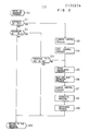
- Fig. 2 shows a flowchart of the interrupt program stored in the ROM, and the program is processed as follows.
- the first timing signal generating circuit SYG1 or the second timing signal generating circuit SYG 2 provides an output to the interrupt control circuit IRC, causing the microprocessor MPU, to interrupt the currently executed program and transfer its operation to the first step SO of the program shown in Fig. 2.
- the first timing signal SY 1 is given to the interrupt control circuit IRC, it is detected in step Sl, and the program proceeds to step S3 in which the current control process is carried out for calculating data required for motor current control and step S4 in which the GSO control process is carried out for calculating data required for controlling the gate signal (GSO) output.
- GSO gate signal
- steps S5 through S9 are carried out for the respective processes as illustrated, and in step S10 the interrupt program ends and the operation returns to the original program. More particularly, in the process of motor current control in step S3, the reference signal PA and feedback signal FA derived from the analog input circuit AIC are compared with each other and the phase angles of the gate signals G5 1 and GS 2 are determined depending on the difference of the two signals. In step S4, the process for controlling the gate signal output circuit GSO takes place so that the gate signals GS 1 and GS 2 are produced according to the phase angles obtained by the process for'the current control in step S3.
- step S5 the frequency of pulses provided by the pulse generator PG and entered through the speed signal input circuit VIC is converted to a value proportional to the car speed by additionally using parameters such as the wheel diameter, and it is given through the analog signal output circuit AOC to the speed meter SM.
- step S6 the slip and skip of wheels are detected using the result of the step S5, and in step S7, the tandem control signal STS is produced from the result of the process in step S5 so as to control the tandem signal output circuit STC.
- step S8 checks the integrity of the results obtained in steps S3 through S7, and if abnormality is found, control is transferred to a corresponding process for halting the vehicle or inhibiting the change of phase angle in the gate signal output circuit GSO.
- step S9 the results of processes in steps S3 through S8 are stored in the memory circuit MEM for the purpose of logging the operational states of the vehicle. The above processes are carried out in well-known manner and no detailed explanation will be necessary.
- step S2 when the second timing signal SY 2 is given to the interrupt control circuit IRC, it is detected in step S2, and the program branches to step Sll for checking whether or not an interrupt by the preceding first timing signal SY has normally occurred. Since the first timing signal SY 1 is generated at a constant frequency in synchronism with the power voltage, the above check can be readily carried out by checking whether the first timing signal SY 1 has occurred within a predetermined time interval corresponding to the constant frequency after the preceding first timing signal. If not occurred, it is determined that the first timing signal has expired. If the timing signal SY 1 is found as normally occurred, the interrupt process based on the timing signal SY 2 is unnecessary and the operation is returned to the original program in step S10.
- the program branches to step S5 and executes the processes in steps S5 through S9. Accordingly, when the car runs through a non-powered section of the trolley wire, the second timing signal generating circuit SYG 2 generates the second timing signal SY 2 to the interrupt control circuit IRC, so that processes necessary even in the non-powered section (e.g., steps S4 through S8 in Fig. 2) are carried out.
- Fig. 3 shows a flowchart of another interrupt program which may be used in place of the program shown in Fig. 2.
- the second timing signal SY 2 is given to the interrupt control circuit IRC, it is detected in step S12, and the program branches to step S3 in which the process for the motor current control takes place. Then, the processes in steps S5 through S9 are carried out, and then the operation returns to the original program at step 510.
- the reference signal PA and feedback signal FA received through the analog input circuit AIC are compared with each other, and the phase angles of the gate signals GS1 and GS2 are determined depending on the difference between the two signals.
- step S5 through S9 are the same as those of the program shown in Fig. 2.
- step S4 the program branches to step S4 for the process of the gate signal output GSO circuit so that the gate signal output GSO circuit is controlled to produce the gate signals GS 1 and GS 2 according to the phase angles obtained by the process for the current control in step S3.
- the second timing signal generating circuit SYG 2 provides the second timing signal SY 2 to the interrupt control circuit IRC, and processes necessary even in the non-powered section (e.g., steps S4 through S8 in Fig. 3) are carried out. Since the control of the gate signal output GSO circuit is carried out in response to the second timing signal SY 1 , the gate signals GS 1 and GS 2 for the thyristors T 1 and T 2 are in synchronism with the power voltage supplied from the trolley wire TW, and the desired control performance is accomplished.
- the process necessary for the phase control initiated by the first timing signal (e.g., step S3 for the current control) is always carried out based on the latest data.
- the above-mentioned integer may be selected to be 2 or larger so that the duty of the processor is reduced while satisfying the desired functions and performance of the system.
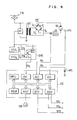
- Figs. 4 and 5 show another embodiment of the present invention.
- the same reference symbols are used for the same or like components as those in Fig. 1.
- the arrangement of Fig. 4 is identical to that of Fig. 1, except that the first and second timing signals SY . and SY 2 are supplied to a timing signal switching circuit SYE made up of a relay RY or the like, which provides a third timing signal SY 3 to the interrupt control circuit IRC.
- a timing signal switching circuit SYE made up of a relay RY or the like, which provides a third timing signal SY 3 to the interrupt control circuit IRC.
- the auxiliary transformer PT provides an output
- the timing signal switching circuit SYE provides the third timing signal SY 3 corresponding to the first timing signal SY, so that the microprocessor MPU is subjected to an interruption by the interrupt control circuit IRC in synchronism with the a.c. power voltage received from the trolley wire TW.
- Fig. 5 shows a flowchart of the interrupt program for the AC electric car control system.
- the microprocessor MPU suspends the currently executing program, and its operation is transferred to step S0.
- the interrupt by the signal SY 3 is detected in step S14, and the processes in steps S3 through S9, which are identical to those of Fig. 2, are carried out.
- the gate signal output circuit GSO is controlled in synchronism with the a.c. power voltage received from the trolley wire TW.
- the auxiliary transformer PT provides no output, and the timing signal switching circuit SYE provides the third timing signal SY 3 based on the second timing signal SY 2 , causing the microprocessor to interrupt its normal program through the interrupt control circuit IRC, and proceed to the same processes as described above. Accordingly, even when the car runs through the non-powered section, all of the processes S3 through S9 are carried out to perform the tandem control function, monitor function, and car speed detection and indication.
- timing signal SY 3 is used for interruption, and the simplifies the interrupt control circuit as well as the program resulting in minimizing the processing time.
- Fig. 6 shows still another embodiment of the present invention, illustrating only those portions corresponding to the timing signal switching circuit SYE, first timing signal generating circuit SYG l and second timing signal generating circuit SYG 2 of Fig. 4.
- Fig. 7 shows a timing chart of the signals produced in the arrangement of Fig. 6.
- the auxiliary transformer PT provides its output to the first timing signal generating circuit SYG 1 , which converts the output into a rectangular first timing signal SY 1 in synchronism therewith, as shown in Fig. 7, and supplies the timing signal SY 1 to an OR gate and also to a one-shot trigger circuit OS.
- the one-shot trigger circuit OS provides a pulse at each transition of the first timing signal SY 1 , and it is supplied to the reset terminal RES of a counter circuit CT.
- an oscillation circuit CG provides output pulses of a frequency larger than that of the first timing signal SY 1 as shown in Fig. 7, and the output pulses are supplied to the clock terminal CK of the counter circuit CT, which is arranged to count down the received pulses and provide a signal at its output terminal OUT at a frequency equal to the output frequency of the auxiliary transformer PT.
- the auxiliary transformer PT provides the output to the circuit SYG 1 , which in turn produces the first timing signal SY 1 so that the one-shot trigger circuit OS provides a pulse at each transition of the SY 1 , causing the counter circuit CT to reset. Therefore, the counter circuit CT does not provide the output, but the first timing signal SY 1 is fed through the OR gate as the third timing signal SY 3 .
- the auxiliary transformer PT and hence the one-shot trigger circuit SO provide no output. Accordingly, the counter circuit CT is not reset, but it counts down the output of the oscillation circuit CG to produce at its output terminal OUT the signal at a frequency equal to that of the first timing signal SY 1 . This signal is fed through the OR gate as the third timing signal SY 3 .
- This embodiment eliminates any delay in the switching operation between the first timing signal SY 1 and the second timing signal.
Landscapes
- Engineering & Computer Science (AREA)
- Power Engineering (AREA)
- Transportation (AREA)
- Mechanical Engineering (AREA)
- Life Sciences & Earth Sciences (AREA)
- Sustainable Development (AREA)
- Sustainable Energy (AREA)
- Electric Propulsion And Braking For Vehicles (AREA)
- Control Of Ac Motors In General (AREA)
- Control Of Direct Current Motors (AREA)
Applications Claiming Priority (2)
| Application Number | Priority Date | Filing Date | Title |
|---|---|---|---|
| JP165185/83 | 1983-09-09 | ||
| JP58165185A JPS6059903A (ja) | 1983-09-09 | 1983-09-09 | 交流電気車の制御装置 |
Publications (3)
| Publication Number | Publication Date |
|---|---|
| EP0135874A2 true EP0135874A2 (fr) | 1985-04-03 |
| EP0135874A3 EP0135874A3 (en) | 1985-06-05 |
| EP0135874B1 EP0135874B1 (fr) | 1987-01-07 |
Family
ID=15807453
Family Applications (1)
| Application Number | Title | Priority Date | Filing Date |
|---|---|---|---|
| EP84110686A Expired EP0135874B1 (fr) | 1983-09-09 | 1984-09-07 | Système de commande pour une voiture électrique à courant alternatif |
Country Status (6)
| Country | Link |
|---|---|
| EP (1) | EP0135874B1 (fr) |
| JP (1) | JPS6059903A (fr) |
| KR (1) | KR910007043B1 (fr) |
| AU (1) | AU549523B2 (fr) |
| DE (1) | DE3461973D1 (fr) |
| ZA (1) | ZA847096B (fr) |
Cited By (2)
| Publication number | Priority date | Publication date | Assignee | Title |
|---|---|---|---|---|
| EP0216358A3 (en) * | 1985-09-27 | 1987-10-14 | Kabushiki Kaisha Toshiba | Power cut detection apparatus for power converter |
| AU681559B2 (en) * | 1995-08-18 | 1997-08-28 | Hitachi Limited | Control system for electric vehicle |
Family Cites Families (2)
| Publication number | Priority date | Publication date | Assignee | Title |
|---|---|---|---|---|
| US4090116A (en) * | 1976-12-10 | 1978-05-16 | General Electric Company | Closed loop digital control system and method for motor control |
| JPS6011544B2 (ja) * | 1979-09-25 | 1985-03-26 | 株式会社東芝 | 同期信号検出回路 |
-
1983
- 1983-09-09 JP JP58165185A patent/JPS6059903A/ja active Pending
-
1984
- 1984-08-30 KR KR1019840005333A patent/KR910007043B1/ko not_active Expired
- 1984-09-05 AU AU32726/84A patent/AU549523B2/en not_active Ceased
- 1984-09-07 EP EP84110686A patent/EP0135874B1/fr not_active Expired
- 1984-09-07 DE DE8484110686T patent/DE3461973D1/de not_active Expired
- 1984-09-10 ZA ZA847096A patent/ZA847096B/xx unknown
Cited By (3)
| Publication number | Priority date | Publication date | Assignee | Title |
|---|---|---|---|---|
| EP0216358A3 (en) * | 1985-09-27 | 1987-10-14 | Kabushiki Kaisha Toshiba | Power cut detection apparatus for power converter |
| US4730245A (en) * | 1985-09-27 | 1988-03-08 | Kabushiki Kaisha Toshiba | Power cut detection apparatus for power converter |
| AU681559B2 (en) * | 1995-08-18 | 1997-08-28 | Hitachi Limited | Control system for electric vehicle |
Also Published As
| Publication number | Publication date |
|---|---|
| ZA847096B (en) | 1985-04-24 |
| AU549523B2 (en) | 1986-01-30 |
| EP0135874B1 (fr) | 1987-01-07 |
| KR910007043B1 (ko) | 1991-09-16 |
| JPS6059903A (ja) | 1985-04-06 |
| EP0135874A3 (en) | 1985-06-05 |
| KR850002816A (ko) | 1985-05-20 |
| AU3272684A (en) | 1985-03-14 |
| DE3461973D1 (en) | 1987-02-12 |
Similar Documents
| Publication | Publication Date | Title |
|---|---|---|
| US5677611A (en) | Control apparatus for an electric vehicle | |
| US5646510A (en) | AC locomotive operation with DC bus current sensor failure | |
| US3898937A (en) | Wheel slip sensing and control system | |
| EP0401057B1 (fr) | Système d'entraînement à vitesse variable | |
| EP0446936A2 (fr) | Contrôleur pour un moteur électrique avec contacteur de dérivation | |
| US5130617A (en) | Inverter control device for driving an elevator | |
| JP3409327B2 (ja) | インバータ装置 | |
| JP5578972B2 (ja) | 交流電車のコンバータ制御装置 | |
| SU1351524A3 (ru) | Система генерировани и распределени электрической энергии | |
| US3790871A (en) | Individual axle wheel slip control system | |
| EP0135874B1 (fr) | Système de commande pour une voiture électrique à courant alternatif | |
| US9716442B2 (en) | Power converter, electric rolling stock and method for controlling sequence test | |
| US4446414A (en) | Terminal voltage limit regulator for a load commutated inverter | |
| JP2672911B2 (ja) | 交流電気車の停電検知方式 | |
| JP3186281B2 (ja) | 交流電気車の制御装置 | |
| JP2003189631A (ja) | 電力変換器回路の停電検知装置 | |
| EP0130547B1 (fr) | Appareil de protection basé sur la détection de la tension pour un système électrique à fréquence variable | |
| JPH0898316A (ja) | 複数モータ制御装置 | |
| JP2003174701A (ja) | 電気車制御装置 | |
| SU1686692A1 (ru) | Устройство дл возбуждени бесщеточного синхронного генератора | |
| JP2001339862A (ja) | 電力系統の安定化方法およびその安定化装置並びに記録媒体 | |
| JPH04285404A (ja) | 電気車の制御装置 | |
| SU1408518A1 (ru) | Устройство дл возбуждени бесщеточного синхронного генератора | |
| KR20080089483A (ko) | 전기차의 구동 제어 장치 | |
| JPS59185102A (ja) | 交流電気車の制御方法 |
Legal Events
| Date | Code | Title | Description |
|---|---|---|---|
| PUAI | Public reference made under article 153(3) epc to a published international application that has entered the european phase |
Free format text: ORIGINAL CODE: 0009012 |
|
| AK | Designated contracting states |
Designated state(s): DE FR GB SE |
|
| PUAL | Search report despatched |
Free format text: ORIGINAL CODE: 0009013 |
|
| AK | Designated contracting states |
Designated state(s): DE FR GB SE |
|
| 17P | Request for examination filed |
Effective date: 19850607 |
|
| 17Q | First examination report despatched |
Effective date: 19860401 |
|
| GRAA | (expected) grant |
Free format text: ORIGINAL CODE: 0009210 |
|
| AK | Designated contracting states |
Kind code of ref document: B1 Designated state(s): DE FR GB SE |
|
| REF | Corresponds to: |
Ref document number: 3461973 Country of ref document: DE Date of ref document: 19870212 |
|
| ET | Fr: translation filed | ||
| PLBE | No opposition filed within time limit |
Free format text: ORIGINAL CODE: 0009261 |
|
| STAA | Information on the status of an ep patent application or granted ep patent |
Free format text: STATUS: NO OPPOSITION FILED WITHIN TIME LIMIT |
|
| 26N | No opposition filed | ||
| EAL | Se: european patent in force in sweden |
Ref document number: 84110686.7 |
|
| PGFP | Annual fee paid to national office [announced via postgrant information from national office to epo] |
Ref country code: FR Payment date: 19970618 Year of fee payment: 14 |
|
| PGFP | Annual fee paid to national office [announced via postgrant information from national office to epo] |
Ref country code: SE Payment date: 19970623 Year of fee payment: 14 Ref country code: GB Payment date: 19970623 Year of fee payment: 14 |
|
| PGFP | Annual fee paid to national office [announced via postgrant information from national office to epo] |
Ref country code: DE Payment date: 19970930 Year of fee payment: 14 |
|
| PG25 | Lapsed in a contracting state [announced via postgrant information from national office to epo] |
Ref country code: GB Free format text: LAPSE BECAUSE OF NON-PAYMENT OF DUE FEES Effective date: 19980907 |
|
| PG25 | Lapsed in a contracting state [announced via postgrant information from national office to epo] |
Ref country code: SE Free format text: LAPSE BECAUSE OF NON-PAYMENT OF DUE FEES Effective date: 19980908 |
|
| GBPC | Gb: european patent ceased through non-payment of renewal fee |
Effective date: 19980907 |
|
| EUG | Se: european patent has lapsed |
Ref document number: 84110686.7 |
|
| PG25 | Lapsed in a contracting state [announced via postgrant information from national office to epo] |
Ref country code: FR Free format text: LAPSE BECAUSE OF NON-PAYMENT OF DUE FEES Effective date: 19990531 |
|
| PG25 | Lapsed in a contracting state [announced via postgrant information from national office to epo] |
Ref country code: DE Free format text: LAPSE BECAUSE OF NON-PAYMENT OF DUE FEES Effective date: 19990701 |
|
| REG | Reference to a national code |
Ref country code: FR Ref legal event code: ST |