EP0135948B1 - Kühlmöbel mit einem umlaufenden Dichtungsrahmen - Google Patents
Kühlmöbel mit einem umlaufenden Dichtungsrahmen Download PDFInfo
- Publication number
- EP0135948B1 EP0135948B1 EP84201030A EP84201030A EP0135948B1 EP 0135948 B1 EP0135948 B1 EP 0135948B1 EP 84201030 A EP84201030 A EP 84201030A EP 84201030 A EP84201030 A EP 84201030A EP 0135948 B1 EP0135948 B1 EP 0135948B1
- Authority
- EP
- European Patent Office
- Prior art keywords
- sealing
- sealing frame
- cover
- container
- bellows
- Prior art date
- Legal status (The legal status is an assumption and is not a legal conclusion. Google has not performed a legal analysis and makes no representation as to the accuracy of the status listed.)
- Expired
Links
- 238000007789 sealing Methods 0.000 title claims abstract description 49
- 238000003825 pressing Methods 0.000 description 4
- 239000002390 adhesive tape Substances 0.000 description 3
- 238000003466 welding Methods 0.000 description 3
- 230000006835 compression Effects 0.000 description 2
- 238000007906 compression Methods 0.000 description 2
- 238000001125 extrusion Methods 0.000 description 2
- 239000000463 material Substances 0.000 description 2
- 230000029058 respiratory gaseous exchange Effects 0.000 description 2
- 239000000853 adhesive Substances 0.000 description 1
- 230000001070 adhesive effect Effects 0.000 description 1
- 230000000903 blocking effect Effects 0.000 description 1
- 238000001816 cooling Methods 0.000 description 1
- 230000000694 effects Effects 0.000 description 1
- 230000037431 insertion Effects 0.000 description 1
- 238000003780 insertion Methods 0.000 description 1
- 238000005304 joining Methods 0.000 description 1
- 238000004519 manufacturing process Methods 0.000 description 1
- 210000004243 sweat Anatomy 0.000 description 1
Images


Classifications
-
- F—MECHANICAL ENGINEERING; LIGHTING; HEATING; WEAPONS; BLASTING
- F25—REFRIGERATION OR COOLING; COMBINED HEATING AND REFRIGERATION SYSTEMS; HEAT PUMP SYSTEMS; MANUFACTURE OR STORAGE OF ICE; LIQUEFACTION SOLIDIFICATION OF GASES
- F25D—REFRIGERATORS; COLD ROOMS; ICE-BOXES; COOLING OR FREEZING APPARATUS NOT OTHERWISE PROVIDED FOR
- F25D17/00—Arrangements for circulating cooling fluids; Arrangements for circulating gas, e.g. air, within refrigerated spaces
- F25D17/04—Arrangements for circulating cooling fluids; Arrangements for circulating gas, e.g. air, within refrigerated spaces for circulating air, e.g. by convection
- F25D17/042—Air treating means within refrigerated spaces
- F25D17/047—Pressure equalising devices
-
- F—MECHANICAL ENGINEERING; LIGHTING; HEATING; WEAPONS; BLASTING
- F25—REFRIGERATION OR COOLING; COMBINED HEATING AND REFRIGERATION SYSTEMS; HEAT PUMP SYSTEMS; MANUFACTURE OR STORAGE OF ICE; LIQUEFACTION SOLIDIFICATION OF GASES
- F25D—REFRIGERATORS; COLD ROOMS; ICE-BOXES; COOLING OR FREEZING APPARATUS NOT OTHERWISE PROVIDED FOR
- F25D23/00—General constructional features
- F25D23/08—Parts formed wholly or mainly of plastics materials
- F25D23/082—Strips
- F25D23/087—Sealing strips
-
- F—MECHANICAL ENGINEERING; LIGHTING; HEATING; WEAPONS; BLASTING
- F25—REFRIGERATION OR COOLING; COMBINED HEATING AND REFRIGERATION SYSTEMS; HEAT PUMP SYSTEMS; MANUFACTURE OR STORAGE OF ICE; LIQUEFACTION SOLIDIFICATION OF GASES
- F25D—REFRIGERATORS; COLD ROOMS; ICE-BOXES; COOLING OR FREEZING APPARATUS NOT OTHERWISE PROVIDED FOR
- F25D2400/00—General features of, or devices for refrigerators, cold rooms, ice-boxes, or for cooling or freezing apparatus not covered by any other subclass
- F25D2400/10—Refrigerator top-coolers
-
- F—MECHANICAL ENGINEERING; LIGHTING; HEATING; WEAPONS; BLASTING
- F25—REFRIGERATION OR COOLING; COMBINED HEATING AND REFRIGERATION SYSTEMS; HEAT PUMP SYSTEMS; MANUFACTURE OR STORAGE OF ICE; LIQUEFACTION SOLIDIFICATION OF GASES
- F25D—REFRIGERATORS; COLD ROOMS; ICE-BOXES; COOLING OR FREEZING APPARATUS NOT OTHERWISE PROVIDED FOR
- F25D2500/00—Problems to be solved
- F25D2500/02—Geometry problems
Definitions
- the invention relates to a refrigerated cabinet with a circumferential mitred sealing frame in the corner regions, in particular for freezers, consisting of a refrigerated goods container and a closet, in the edge regions of which the sealing frame is arranged and in the closed state closes the opening of the refrigerated goods container airtight, the Sealing bellows of the sealing frame has means for accelerated pressure equalization when opening and closing the closure lid.
- German patent 1 601 171 discloses a sealing frame for a refrigerated cabinet consisting of a profile seal, which has an air passage in the profile seal which is connected to the outside air and which is covered against the interior of the freezer by an additional lip seal. With this arrangement it is achieved that with the closing of the freezer door a rapid pressure equalization between the air in the refrigerator and the outside air surrounding the refrigerator can take place.
- the air outlet itself is designed as a through hole in the profile seal.
- a further profile seal arrangement for refrigerated cabinets in which a deliberately induced constriction of the breathing height of the sealing frame is brought about in order to reduce the opening forces in refrigerated cabinet doors.
- the sealing frame is partially with a tape that z. B. can be an adhesive tape, constricted.
- the effect of this measure is that when lifting the refrigerator lid, d. H. when the opening force is applied at the points of the constriction, the air balance between the interior of the refrigerator and the outside air can occur earlier, so that the force required for opening is reduced.
- the disadvantage of this measure is to be seen in the fact that the constrictions have to be made subsequently by wrapping the sealing frame with the adhesive tape at the places provided for this purpose.
- the constrictions can be produced, for example, by additional work steps if the sealing frame is already connected to one another in the corner regions. Then one or more such radial constrictions are made at a point to be determined above the longitudinal extent of the sealing frame by wrapping with the adhesive tape.
- the constrictions can also be on the unconnected profile sealing parts. are produced, after which the individual profile sealing parts are then built up in the corner areas by a corresponding connection to the sealing frame.
- the object of the invention is seen primarily in the creation of a sealing frame for a refrigerated cabinet which receives the means for accelerated pressure equalization in the areas of the weld seams without additional work steps during the assembly of the frame parts to form the sealing frame.
- the height of the sealing bellows in the miter corners in the unloaded state is reduced to one, which is up to 2 mm above the gap height between the refrigerated goods container and the closed lid.
- the reduction in cross-section advantageously takes place when the profile individual parts sweat into the sealing frame.
- the sealing frame according to the invention takes advantage of the possibility, when joining the sealing frame parts in the corner areas, to permanently introduce the reduction in cross section in a single work step, which is necessary for rapid pressure compensation when the refrigerator lid is opened.
- the invention also takes advantage of the fact that when the individual profile lengths of the sealing frame are joined in the miter corner areas by the application of welding heat, the plastic material used to produce the sealing profile is plasticized, which can not only be used to connect the individual profile parts, but simultaneously for permanent lowering of the cross-section of the profile seal in the connection area of the mitred corners.
- the plastic material is pressed into the profile seal in these areas and remains in this pressed state due to cooling.
- the corner welding and the synchronously reducing cross-section can be adjusted so that a breathing movement of the sealing frame is still possible in the corner area with reduced cross-section.
- this distance can be adjusted up to 2 mm and depends on the weight of the refrigerator lid and the size of the refrigerator itself. In any case, it is essential that this distance information maintains a reduced sealing area which it is easy to overcome when the refrigerator lid is opened, before pressure equalization takes place.
- the profile seal 1 is shown, which consists of the profile foot 2 and the bellows 3.
- the profile foot 2 consists of the latching parts 21, 22, which ensure a secure fit of the sealing frame on the closure cover.
- the sealing bellows 3 consists in the illustration shown of a three-part hollow profile. This three-way division takes place through the blocking walls 31, 32, 33 formed in the sealing bellows 3, which together with the outer walls 34, 35, 36 of the sealing bellows 3 form the partial hollow chambers 37, 38, 39.
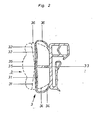
- FIG. 2 shows the profile seal according to FIG. 1 in its working areas.
- 1 shows the profile seal in its extrusion state
- FIG. 2 shows the state of the seal as it results after insertion into the sealing cap as a permanent deformation due to the working pressures occurring.
- the outer walls 34 and 36 of the sealing bellows have been rounded in the shape of the permanent deformation shown in dashed lines and pushed outwards.
- the inner webs 31, 32 have followed this movement outwards. They now form with the inner web 33 a flattened Y shape compared to the illustration in FIG. 1.
- the outer wall 35 of the sealing bellows 3 has also flattened in its bulges.
- FIG. 2 shows, compared to the permanent deformation of the profile seal in the dashed version, the position of the highest compression when the closure lid rests on the refrigerated goods container.
- the outer walls 34, 36 of the sealing bellows 3 are pressed even further outward, the inner webs 31, 32 are positioned almost at right angles to the inner web 33 and the outer wall 35 bears approximately on the inner webs 31, 32. It is easy to see from this illustration that a further compression of the sealing bellows 3 is no longer possible, since the inner web 33 and the inner webs 31, 32 articulated thereon would oppose this.
- FIG. 3 shows the profile seal in the welded corner areas.
- the end region of the pressing according to FIG. 2 has not yet been reached; H. the outer wall 35 of the sealing bellows 3 still protrudes slightly from the inner webs 31, 32.
- the difference between the final pressing of the profile seal shown in FIG. 2 and the distance between the corner weld shown in FIG. 3 shows the possibility of pressing in the welded corner areas.
Landscapes
- Engineering & Computer Science (AREA)
- Chemical & Material Sciences (AREA)
- Combustion & Propulsion (AREA)
- Physics & Mathematics (AREA)
- Mechanical Engineering (AREA)
- Thermal Sciences (AREA)
- General Engineering & Computer Science (AREA)
- Refrigerator Housings (AREA)
- Closures For Containers (AREA)
Description
- Die Erfindung betrifft ein Kühlmöbel mit einem umlaufenden, in den Eckbereichen auf Gehrung miteinander verbundenen Dichtungsrahmen, insbesondere für Gefriertruhen, bestehend aus einem Kühlgutbehälter und einem Verschlundekkel, in dessen Randbereichen der Dichtungsrahmen angeordnet ist und in geschlossenem Zustand die Öffnung des Kühlgutbehälters luftdicht abschließt, wobei der Dichtungsbalg des Dichtungsrahmens Mittel zum beschleunigten Druckausgleich bei Öffnungs-und Schlienmaßnahmen des Verschlundeckels aufweist.
- Aus dem Deutschen Patent 1 601 171 ist ein aus einer Profildichtung bestehender Dichtungsrahmen für ein Kühlmöbel bekannt, welcher einen in der profildichtung mit der Außenluft in Verbindung stehenden Luftdurchlan aufweist, der gegen den Innenraum der Gefriertruhe hin durch eine zusätzliche Lippendichtung abgedeckt ist. Mit dieser Anordnung wird erreicht, daß mit dem Schließen der Gefriertruhentür ein rascher Druckausgleich zwischen der Luft im Kühlraum und der das Kühlmöbel umgebenden Außenluft stattfinden kann. Der Luftdurchlaß selbst ist in der Profildichtung als Durchgangsbohrung ausgebildet.
- Der Nachteil dieses bekannten Prinzips ist darin zu sehen, dan die Luft-Durchgangsbohrung in die Profildichtung nach deren Herstellung eingebracht werden mun. Da auf die Länge der Profildichtung verteilt mehrere solcher Durchgangsbohrungen angeordnet sein müssen, um einen optimalen Luftausgleich zwischen dem Innenraum des Kühlmöbels und der Außenluft zu erzielen, ist ein erheblicher Arbeitsaufwand erforderlich, um die entsprechenden Öffnungen in die Profildichtung einzubringen.
- Aus der US-Patentschrift 3 201 833 ist eine weitere Profildichtungs-Anordnung für Kühlmöbel bekannt, bei der zur Verringerung der Öffnungskräfte bei Kühlmöbeltüren eine bewußt herbeigeführte Einschnürung der Atmungshöhe des Dichtungsrahmens herbeigeführt wird. Zu diese Zweck wird der Dichtungsrahmen partiell mit einem Band, das z. B. ein Klebeband sein kann, eingeschnürt. Die Wirkung dieser Maßnahme ist die, daß beim Anheben des Kühlmöbel-Deckel, d. h. beim Aufbringen der Offnungskraft an den Stellen der Einschnürung früher der Luftausgleich zwischen dem Innenraum des Kühlmöbels und der Außenluft eintreten kann, so daß die zur Offnung erforderliche Kraftaufwendung verringert wird. Der Nachteil dieser Maßnahme ist darin zu sehen, daß die Einschnürungen durch Umwickeln des Dichtungsrahmens an den dafür vorgesehenen Stellen mit dem Klebeband nachträglich vorgenommen werden müssen. Die Einschnürungen können beispielsweise durch zusätzliche Arbeitsgänge hergestellt werden, wenn der Dichtungsrahmen in den Eckbereichen bereits miteinwander verbunden ist. Danach wird dam an einer festzulegenden Stelle über der Längsausdehnung des Dichtungsrahmens eine oder mehrere solcher radialen Einschnürungen durch Umwickeln mit dem Klebeband hergestellt. Die Einschnürungen können aber auch bereits an den unverbundenen Profildichtungsteilen . hergetellt werden, wonach dann die einzelnen Profildichtungsteile in den Eckbereichen durch entsprechende Verbindung zu dem Dichtungsrahmen aufgebaut werden.
- Hier setzt die Erfindung ein, die es sich zur Aufgabe gestellt hat, die Nachteile des bekannten Standes der Technik - insbesondere der Nachbearbeitung der Profildichtungsteile - zu vermeiden.
- Die Aufgabe der Erfindung wird in erster Linie darin gesehen, einen Dichtungsrahmen für ein Kühlmöbel zu schaffen, welcher ohne zusätzliche Arbeitsschritte während des Zusammenf'ugens der Rahmenteile zu den Dichtungsrahmen in den Bereichen der Schweißnähte die Mittel zum beschleunigten Druckausgleich erhält. Erfindungsgemäß wird dazu vorgeschlagen, daß die Höhe des Dichtungsbalges in den Gehrungsecken in unbelastetem Zustand auf ein Man verringert ist, welches bis zu 2 mm über der Spalthöhe zwischen dem Kühlgutbehälter und dem geschlossenen Deckel liegt.
- Vorteilhaft erfolgt die Querschnittsverringerung bei der Verschweinung der Profileinzelteile zu dem Dichtungsrahmen.
- Der erfindungsgemäße Dichtungsrahmen macht sich die Möglichkeit zunutze, beim Zusammenfügen der Dichtungsrahmenteile in den Eckbereichen in einem einzigen Arbeitsschritt die Querschnittsverringerung bleibend einzubringen, die für einen schnellen Druckausgleich beim Öffnen des KühlmöbelDeckels erforderlich ist. Die Erfindung macht sich weiterhin die Tatsache zunutze, daß beim Zusammenfügen der einzelnen Profillängen des Dichtungsrahmens in den Gehrungseckbereichen durch die Applikation von Schweißwärme eine Plastifizierung des zur Herstellung des Dichtungsprofils verwendeten Kunststoffmaterials stattfindet, die nicht nur zum Verbinden der einzelnen Profilteile verwendet werden kann, sondern gleichzeitig zur bleibenden Absenkung des querschnittes der Profildichtung im Verbindungsbereich der Gehrungsecken.
- Das Kunststoffmaterial wird in diesen Bereichen in die Profildichtung hinein verdrückt und bleibt durch Abkühlung in diesem Verdrückten Zustand stehen. Die Eckverschweißung und die damit synchron laufende Querschnittsverringerung kann dabei so eingestellt werden, daß auch im querschnittsverringerten Eckbereich eine atmende Bewegung des Dichtungsrahmens noch möglich ist.
- Dies ist insbesondere deswegen erforderlich, weil beim Anheben des Kühlmöbeldeckels eine gewisse Kraft erforderlich sein muß, bis durch Abheben der Dichtung in den Eckbereichen der Druckausgleich stattfindet, da sonst eine luftdichte Absperrung des Kühlgutbehälters nicht erzielbar wäre.
- Diese verringerte Kraft ergibt sich aus der Tatsache, daß die Dichtung im Gehrungseckbereich bis zu einem Abstand abgeschweißt ist, der geringfügig über dem Scharnierabstand (= Spalthöhe) zwischen dem Verschlußdeckel und dem Kühlgutbehälter liegt. Dieser Abstand ist erfindungsgemäß bis zu 2 mm einstellbar und richtet sich nach dem Gewicht des Kühlmöbeldeckels sowie der Größe des Kühlmöbels selbst. Wesentlich ist jedenfalls, daß mit dieser Abstandsangabe ein verringerter Dichtbereich erhalten bleibt, den es glit, bei der Offnung des Kühlmöbeldeckels zu überwinden, bevor der Druckausgleich stattfindet.
- In der Zeichnung ist im Querschnitt eine Profildichtung schematisch dargestellt, die zu einem erfindungsgemäßen Dichtungsrahmen verarbeitet werden kann. Es zeigt:
- Fig. 1 die Profildichtung im Extrusionszustand
- Fig. 2 die Profildichtung in ihren Arbeitsbereichen
- Fig. 3 die Profildichtung in den abgeschweißten Eckbereichen
- In Fig. 1 ist die Profildichtung 1 gezeigt, welche aus dem Profilfuß 2 und dem Dichtbalg 3 besteht. Der Profilfuß 2 beteht aus den Verrasterungsteilen 21, 22, welche für einen sicheren Sitz des Dichtungsrahmens an dem Verschlußdeckel sorgen. Der Dichtbalg 3 besteht in der gezeigten Darstellung aus einem dreigeteilten Hohlprofil. Diese Dreiteilung erfolgt durch die im Dichtbalg 3 eingeformten Sperrwände 31, 32, 33, welche zusammen mit den Außenwänden 34, 35, 36 des Dichtbalges 3 die Teilhohlkammern 37, 38, 39 bilden.
- In Fig. 2 ist die Profildichtung gemäß Fig. 1 in ihren Arbeitsbereichen dargestellt. Zeigt Fig. 1 noch die Profildichtung in ihrem Extrusionszustand, so gibt Fig. 2 den Zustand der Dichtung wieder, wie er sich nach dem Einsetzen in den Verschlußdeckel als bleibende Verformung -bedingt durch die auftretenden Arbeitsdrücke - ergibt. Die Außenwände 34 und 36 des Dichtbalges haben sich in der gestrichelt dargestellten Form der bleibenden Verformung gerundet und nach außen geschoben. Die Innenstege 31, 32 sind dieser Bewegung nach außen gefolgt. Sie bilden nunmehr mit dem Innensteg 33 eine gegenüber der Darstellung in Fig. 1 abgeflachte Y-Form. Die Außenwand 35 des Dichtbalges 3 hat sich ebenfalls in ihren Ausbauchungen verflacht.
- In den voll gezeichneten Umrissen zeigt Fig. 2 gegenüber der bleibenden Verformung der Profildichtung in der gestrichelten Ausführung die Lage der höchsten Verpressung beim Aufliegen des Verschlußdeckels auf dem Kühlgutbehälter. Die Außenwände 34, 36 des Dichtungsbalgs 3 sind noch weiter nach außen gedrückt, die Innenstege 31, 32 sind nahezu rechtwinkelig zum Innensteg 33 gestellt und die Außenwand 35 liegt annähernd an den Innenstegen 31, 32 an. Aus dieser Darstellung wird leicht ersichtlich, daß ein weiteres Zusammenpressen des Dichtungsbalges 3 nicht mehr möglich ist, da sich dem der Innensteg 33 und die daran angelenkten Innenstege 31, 32 entgegenstellen würden.
- Gegenüber der Darstellung des wirksamen Arbeitsbereiches des Dichtprofils in Fig. 2 zeigt Fig. 3 die Profildichtung in den abgeschweißten Eckbereichen. Hier ist der Endbereich der Verpressung gemäß Fig. 2 noch nicht erreicht, d. h. die Außenwand 35 des Dichtbalges 3 steht noch geringfügig von den Innenstegen 31, 32 ab.
- Der Unterschied zwischen der in Fig. 2 gezeigten Endverpressung der Profildichtung und dem Abstand der in Fig. 3 gezeigten Eckverschweißung zeigt die Verpressmöglichkeit in den geschweißten Eckbereichen. Beim Öffnen des Verschlußdeckels ist lediglich so viel Kraft aufzuwenden, die erforderlich ist, um das Dichtprofil aus der in Fig. 2 gezeigten Stellung der Endverpressung auf die in Fig. 3 gezeigten Bereich der Eckenabschweißung zu bringen. Sobald die zum Offnen aufgewendete Kraft über den in Fig. 3 gezeigten Eckenabschweiß-Bereich hinausgeht, tritt der Druckausgleich zwischen dem Innenraum des Kühlmöbels und der Außenathmosphäre ein. Danach hebt der Verschlußdeckel völlig vom Kühlgutbehälter ab.
- Bei der weiteren Offnung aus der Situation der Fig. 3 bis zum gestrichelten Bereich der Fig. 2 muß dann die Öffnungskraft nicht mehr gegen einen erhöhten Innendruck gerichtet werden, sondern sie hat hier lediglich noch die Adhäsionskräfte des Dichtungsrahmens gegenüber dem Kühlgutbehälter zu überwinden.
Claims (1)
- Kühlmöbel mit einem umlaufenden, in den Eckbereichen auf Gehrung miteinander verbundenen Dichtungsrahmen, insbesondere für Gefriertruhen, bestehend aus einem Kühlgutbehälter und einem Verschlußdeckel, in dessen Randbereichen der Dichtungsrahmen angeordnet ist und in geschlossenem Zustand die Öffnung des Kühlgutbehälters luftdicht abschließt, wobei der Dichtungsbalg des Dichtungsrahmens Mittel zum beschleunigten Druckausgleich bei Öffnungs- und Schließmaßnahmen des Verschlußtdeckels aufweist, dadurch gekennzeichnet, daß die Mittel dadurch gebildet sind, daß die Höhe des Dichtungsbalges (3) in den Gehrungsecken in unbelastetem Zustand auf ein Maß verringert ist, welches bis zu 2 mm über der Spalthöhe zwischen dem Kühlgutbehälter und dem geschlossenen Deckel liegt.
Priority Applications (1)
| Application Number | Priority Date | Filing Date | Title |
|---|---|---|---|
| AT84201030T ATE24963T1 (de) | 1983-08-27 | 1984-07-12 | Kuehlmoebel mit einem umlaufenden dichtungsrahmen. |
Applications Claiming Priority (2)
| Application Number | Priority Date | Filing Date | Title |
|---|---|---|---|
| DE3330991 | 1983-08-27 | ||
| DE3330991A DE3330991C2 (de) | 1983-08-27 | 1983-08-27 | Kühlmöbel mit einem umlaufenden Dichtungsrahmen |
Publications (2)
| Publication Number | Publication Date |
|---|---|
| EP0135948A1 EP0135948A1 (de) | 1985-04-03 |
| EP0135948B1 true EP0135948B1 (de) | 1987-01-14 |
Family
ID=6207633
Family Applications (1)
| Application Number | Title | Priority Date | Filing Date |
|---|---|---|---|
| EP84201030A Expired EP0135948B1 (de) | 1983-08-27 | 1984-07-12 | Kühlmöbel mit einem umlaufenden Dichtungsrahmen |
Country Status (3)
| Country | Link |
|---|---|
| EP (1) | EP0135948B1 (de) |
| AT (1) | ATE24963T1 (de) |
| DE (1) | DE3330991C2 (de) |
Cited By (1)
| Publication number | Priority date | Publication date | Assignee | Title |
|---|---|---|---|---|
| DE102011103967A1 (de) | 2011-04-08 | 2012-10-11 | Liebherr-Hausgeräte Ochsenhausen GmbH | Kühl- und /oder Gefriergerät |
Families Citing this family (6)
| Publication number | Priority date | Publication date | Assignee | Title |
|---|---|---|---|---|
| DE3709060C2 (de) * | 1987-03-19 | 1996-04-04 | Ilpea Kunststoffverarbeitung | Dichtungsanordnung für Kühlmöbel, insbesondere Kühltruhen |
| DE9410579U1 (de) * | 1994-06-30 | 1994-09-01 | Rehau Ag + Co, 95111 Rehau | Profil zur Dichtung einer Tür |
| DE29520234U1 (de) * | 1995-12-20 | 1997-04-17 | Liebherr-Hausgeräte GmbH, 88416 Ochsenhausen | Profil zur Dichtung einer Tür oder Klappe gegenüber einem Korpusteil |
| US8490333B2 (en) | 2005-05-23 | 2013-07-23 | Electrolux Home Products, Inc. | Sealing gaskets |
| CN110806058A (zh) * | 2019-11-27 | 2020-02-18 | 合肥美科制冷技术有限公司 | 一种冰箱密封结构及冰箱 |
| TWI762169B (zh) * | 2021-01-28 | 2022-04-21 | 緯創資通股份有限公司 | 輸液高度示警與阻斷裝置及輸液高度示警與阻斷方法 |
Family Cites Families (7)
| Publication number | Priority date | Publication date | Assignee | Title |
|---|---|---|---|---|
| DE1239215B (de) * | 1962-11-21 | 1967-04-20 | Canfield Co Gmbh H O | Einrichtung zur Schweissverbindung von elastischen, zusammenstossenden Hohlprofildichtungen gleicher Umfangslaenge fuer Schraenke mit Magnetverschluss |
| US3201833A (en) * | 1963-08-22 | 1965-08-24 | Carrier Corp | Sealing arrangement |
| US3331648A (en) * | 1965-05-28 | 1967-07-18 | Gen Motors Corp | Refrigerating apparatus |
| DE1601901A1 (de) * | 1967-10-13 | 1970-05-21 | Licentia Gmbh | Dichtung fuer Kuehlschranktueren |
| US3434239A (en) * | 1968-03-25 | 1969-03-25 | Whirlpool Co | Snap-on vacuum break device for refrigerators |
| FR2445916A1 (fr) * | 1979-01-04 | 1980-08-01 | Refrigeration Cie Caladoise | Appareil de production de froid, muni d'un systeme de reequilibrage de pressions |
| FR2459871A1 (fr) * | 1979-06-27 | 1981-01-16 | Rubberia Sa | Joint a levre pour bati ouvrant et son procede de fabrication |
-
1983
- 1983-08-27 DE DE3330991A patent/DE3330991C2/de not_active Expired
-
1984
- 1984-07-12 AT AT84201030T patent/ATE24963T1/de not_active IP Right Cessation
- 1984-07-12 EP EP84201030A patent/EP0135948B1/de not_active Expired
Cited By (1)
| Publication number | Priority date | Publication date | Assignee | Title |
|---|---|---|---|---|
| DE102011103967A1 (de) | 2011-04-08 | 2012-10-11 | Liebherr-Hausgeräte Ochsenhausen GmbH | Kühl- und /oder Gefriergerät |
Also Published As
| Publication number | Publication date |
|---|---|
| DE3330991A1 (de) | 1985-03-14 |
| ATE24963T1 (de) | 1987-01-15 |
| EP0135948A1 (de) | 1985-04-03 |
| DE3330991C2 (de) | 1986-08-14 |
Similar Documents
| Publication | Publication Date | Title |
|---|---|---|
| EP0563827A2 (de) | Wandelement und/oder Tür mit niedrigem Wärmedurchgangskoeffizient | |
| DE3330991C2 (de) | Kühlmöbel mit einem umlaufenden Dichtungsrahmen | |
| DE1659722C3 (de) | Tür mit einem feststehenden Rahmen, mit einem Flügelrahmen und mit einer Füllung | |
| EP1581716B1 (de) | Vorrichtung zum abdichten von geb ude ffnungen | |
| DE102008023500A1 (de) | Tür mit einer Bodendichtung | |
| EP0576867A2 (de) | Rahmen für Fenster aus Kunststoff | |
| DE9410579U1 (de) | Profil zur Dichtung einer Tür | |
| DE3709060C2 (de) | Dichtungsanordnung für Kühlmöbel, insbesondere Kühltruhen | |
| EP0062153B1 (de) | Rahmenförmige Dichtung aus Kunststoff für die Tür eines Kühlmöbels | |
| EP1691025A2 (de) | Rahmen-Baugruppe sowie Luftstrombegrenzungseinrichtung hierfür | |
| DE2406434A1 (de) | Anordnung mit einer schlauchprofildichtung fuer eine fahrzeugtuer | |
| EP3783180B1 (de) | Verstärkungsprofilfixierung | |
| EP2662521B1 (de) | Rollladenkasten | |
| DE69718891T2 (de) | Rahmenförmige Dichtung aus elastomerem Material, insbesondere für Ofentüren | |
| DE60214736T2 (de) | Wärmesperre für luftbehandlungseinheits-schrank | |
| DE3446948C2 (de) | ||
| DE3902938C1 (en) | Sectional door | |
| AT409524B (de) | Profildichtung | |
| EP1170563A2 (de) | Kühlmöbel, insbesondere Kühlschrank oder Gefrierschrank | |
| EP3988757B1 (de) | Strangdichtung aus elastischem schaummaterial | |
| DE1709345C2 (de) | Fenster o.dgl. | |
| DE102018127416B3 (de) | Nutzfahrzeugaufbau und Dichtungsanordnung zur Verwendung in einem Nutzfahrzeugaufbau | |
| DE10150833B4 (de) | Gummielastische Dichtung, insbesondere für Außenschwingtüren bei Fahrzeugen | |
| DE102014109130A1 (de) | Dichtkappe | |
| DE3040625C2 (de) |
Legal Events
| Date | Code | Title | Description |
|---|---|---|---|
| PUAI | Public reference made under article 153(3) epc to a published international application that has entered the european phase |
Free format text: ORIGINAL CODE: 0009012 |
|
| AK | Designated contracting states |
Designated state(s): AT FR IT |
|
| 17P | Request for examination filed |
Effective date: 19850619 |
|
| RAP1 | Party data changed (applicant data changed or rights of an application transferred) |
Owner name: REHAU AG + CO |
|
| GRAA | (expected) grant |
Free format text: ORIGINAL CODE: 0009210 |
|
| AK | Designated contracting states |
Kind code of ref document: B1 Designated state(s): AT FR IT |
|
| REF | Corresponds to: |
Ref document number: 24963 Country of ref document: AT Date of ref document: 19870115 Kind code of ref document: T |
|
| ITF | It: translation for a ep patent filed | ||
| ET | Fr: translation filed | ||
| PLBE | No opposition filed within time limit |
Free format text: ORIGINAL CODE: 0009261 |
|
| STAA | Information on the status of an ep patent application or granted ep patent |
Free format text: STATUS: NO OPPOSITION FILED WITHIN TIME LIMIT |
|
| 26N | No opposition filed | ||
| ITTA | It: last paid annual fee | ||
| PGFP | Annual fee paid to national office [announced via postgrant information from national office to epo] |
Ref country code: FR Payment date: 20000517 Year of fee payment: 17 |
|
| PG25 | Lapsed in a contracting state [announced via postgrant information from national office to epo] |
Ref country code: FR Free format text: LAPSE BECAUSE OF NON-PAYMENT OF DUE FEES Effective date: 20020329 |
|
| REG | Reference to a national code |
Ref country code: FR Ref legal event code: ST |
|
| PGFP | Annual fee paid to national office [announced via postgrant information from national office to epo] |
Ref country code: AT Payment date: 20030924 Year of fee payment: 20 |
|
| PG25 | Lapsed in a contracting state [announced via postgrant information from national office to epo] |
Ref country code: AT Free format text: LAPSE BECAUSE OF EXPIRATION OF PROTECTION Effective date: 20040712 |