EP0136000A2 - Papiermaschine - Google Patents
Papiermaschine Download PDFInfo
- Publication number
- EP0136000A2 EP0136000A2 EP84304886A EP84304886A EP0136000A2 EP 0136000 A2 EP0136000 A2 EP 0136000A2 EP 84304886 A EP84304886 A EP 84304886A EP 84304886 A EP84304886 A EP 84304886A EP 0136000 A2 EP0136000 A2 EP 0136000A2
- Authority
- EP
- European Patent Office
- Prior art keywords
- cover
- wire
- lead
- forming machine
- paper forming
- Prior art date
- Legal status (The legal status is an assumption and is not a legal conclusion. Google has not performed a legal analysis and makes no representation as to the accuracy of the status listed.)
- Granted
Links
- 239000011888 foil Substances 0.000 claims abstract description 83
- XLYOFNOQVPJJNP-UHFFFAOYSA-N water Substances O XLYOFNOQVPJJNP-UHFFFAOYSA-N 0.000 claims abstract description 24
- 239000007787 solid Substances 0.000 claims abstract description 9
- 239000002131 composite material Substances 0.000 claims abstract 2
- 238000011144 upstream manufacturing Methods 0.000 claims description 5
- 230000001154 acute effect Effects 0.000 claims description 2
- 230000015572 biosynthetic process Effects 0.000 description 5
- 239000000919 ceramic Substances 0.000 description 5
- 230000009286 beneficial effect Effects 0.000 description 4
- 230000003068 static effect Effects 0.000 description 4
- 230000003247 decreasing effect Effects 0.000 description 3
- 239000000463 material Substances 0.000 description 3
- 238000000034 method Methods 0.000 description 3
- 238000004140 cleaning Methods 0.000 description 2
- 230000005484 gravity Effects 0.000 description 2
- 239000004698 Polyethylene Substances 0.000 description 1
- 230000003749 cleanliness Effects 0.000 description 1
- 230000007423 decrease Effects 0.000 description 1
- 230000000977 initiatory effect Effects 0.000 description 1
- 238000004519 manufacturing process Methods 0.000 description 1
- 229920003023 plastic Polymers 0.000 description 1
- 239000004033 plastic Substances 0.000 description 1
- -1 polyethylene Polymers 0.000 description 1
- 229920000573 polyethylene Polymers 0.000 description 1
- 229920000642 polymer Polymers 0.000 description 1
- 238000009877 rendering Methods 0.000 description 1
- 230000000717 retained effect Effects 0.000 description 1
- 238000000926 separation method Methods 0.000 description 1
- 229910001220 stainless steel Inorganic materials 0.000 description 1
- 239000010935 stainless steel Substances 0.000 description 1
- UONOETXJSWQNOL-UHFFFAOYSA-N tungsten carbide Chemical compound [W+]#[C-] UONOETXJSWQNOL-UHFFFAOYSA-N 0.000 description 1
Images

Classifications
-
- D—TEXTILES; PAPER
- D21—PAPER-MAKING; PRODUCTION OF CELLULOSE
- D21F—PAPER-MAKING MACHINES; METHODS OF PRODUCING PAPER THEREON
- D21F9/00—Complete machines for making continuous webs of paper
- D21F9/003—Complete machines for making continuous webs of paper of the twin-wire type
-
- D—TEXTILES; PAPER
- D21—PAPER-MAKING; PRODUCTION OF CELLULOSE
- D21F—PAPER-MAKING MACHINES; METHODS OF PRODUCING PAPER THEREON
- D21F3/00—Press section of machines for making continuous webs of paper
-
- D—TEXTILES; PAPER
- D21—PAPER-MAKING; PRODUCTION OF CELLULOSE
- D21F—PAPER-MAKING MACHINES; METHODS OF PRODUCING PAPER THEREON
- D21F1/00—Wet end of machines for making continuous webs of paper
- D21F1/48—Suction apparatus
Definitions
- the present invention relates to twin wire paper forming machines and in particular to dewatering apparatus therefor.
- a bottom wire passes over a lead-in-foil and moves along a path towards and over a sheet transfer box.
- an endless top wire after passing round a lead-in roll is brought into contact with the top wire and is subsequently separated from the bottom wire in the region of the transfer box and is passed round a'drive roll whence it returns to the lead-in roll.
- Stock on the bottom wire is contained between the top and bottom wires and water is expelled from the stock during passage of the wires between the lead-in-foil and the sheet transfer box.
- a contact element has been provided above the path of the wires between the lead-in-foil and the sheet transfer box to promote dewatering. Water expelled has fallen under gravity and dewatering has been further promoted by providing the contact element or cover with a discontinuous wire engaging surface with or without suction to promote dewatering in an upward direction.
- discontinuous surface has in practice had the disadvantage that slots or perforations forming the discontinuous surface could become plugged or blocked under certain conditions especially when used in conjunction with groundwood stock with a high fines content thereby decreasing the dewatering action and creating operating problems and rendering the production'of high quality, and even uniform quality, paper difficult to attain.
- a twin wire paper forming machine in which a bottom wire passes over a lead-in-foil and over a sheet transfer box downstream therefrom, and an endless top wire which turns over a lead-in roll and meets the bottom wire in the region of the lead-in-foil cover and is separated from the bottom wire in the region of the sheet transfer box to pass over a drive roll and return to the lead-in roll, and the bottom wire passes over a secondary foil cover which is disposed downstream of the lead-in-foil cover and has alternately solid and open bottom wire engaging areas and the top wire passes below a trailing cover which is disposed downstream of the secondary foil cover and has a continuous top wire engaging surface of which the leading edge serves to doctor water on the top wire into a secondary autoslice.
- leading edge of the sheet transfer box is immediately upstream of the point where the top wire is separated from the stock retained on the bottom wire.
- the sheet transfer box preferably has a slotted or perforated cover and a vacuum is created therein so that suction is applied to the stock before and after the point of separation of the top and bottom wires which is somewhere midway of the slotted or perforated -suction area.
- the lead-in-foil cover has a curved surface and the tension of the wires presses the two wires together to start a first dewatering action.
- the lead-in-foil can have as wire engaging surface either a blank or continuous cover or a slotted cover.
- the slotted cover can be used with or without a vacuum created in the box below it. In the former case, when the cover can be, for example, a ceramic, only upward dewatering results, whilst in the latter case both upward and downward dewatering takes place.
- the alternating solid and open areas of the secondary foil cover give rise to pulses which are beneficial to paper formation.
- These alternating solid and open areas can be created by a series of transverse bars or transverse blades: either arrangement imparts a pulsating pressure to the wires to expel water alternately upwardly and downwardly.
- a short contact time between the bottom wire and each bar or blade gives a pressure pulse to the stock which is beneficial to good paper formation.
- the downward flow doctored from the bottom wire by the leading edges of the foil strips or bars, or blades, forming the secondary foil cover may be encouraged by introducing a vacuum into the secondary foil box below the cover.
- the water pushed upwardly through the top wire is doctored off it by the leading edge of the secondary trailing cover into the secondary autoslice and upwardly into a secondary chamber or saveall, preferably with vacuum assistance.
- the secondary trailing cover is preferably blank, that is to say, it presents a continuous top wire engaging surface, and therefore stock that is pressed between the two wires is now dewatered in a downward direction.
- the secondary trailing cover is preferably ceramic, but can equally well be of any material conventionally used for static wire contacting elements used in a paper machine former.
- the radius of curvature of the secondary trailing cover is preferably smaller than that of the secondary foil cover in order to increase the pressure on the stock between the wires.
- the sheet transfer box preferably has a convex surface and has a vacuum applied thereto to assure transfer of the sheet of paper to the bottom wire.
- a further or primary trailing cover and a further or primary autoslice Whilst all the water expelled upwardly can be doctored.by the leading edge of the secondary trailing cover and withdrawn by the secondary autoslice, a further or primary trailing cover and a further or primary autoslice can be provided above the top wire intermediate the lead-in-foil and the secondary foil cover.
- the primary trailing cover is preferably solid or blank, that is to say, it presents a continuous top wire engaging surface, and is preferably convex.
- the doctored water removed by the primary trailing cover proceeds into a primary autoslice chamber or saveall, preferably with light vacuum assistance.
- the lead-in roll is provided with upward and downward movement.
- the lead-in-foil and secondary foil are provided with an adjusting mechanism which enables them to be moved up and down and to rotate with respect to the wire line.
- the or each autoslice is preferably inclined with respect to the wire line and preferably at an acute angle with respect thereto.
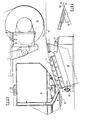
- a twin wire paper forming machine comprises an endless top wire 14 entrained around rolls, including a lead-in roll 12 and a drive roll 13.
- the top wire 14 meets a bottom wire 15 over a convex lead-in-foil cover 1 of a lead-in-foil body 2.
- the wires move in a direction indicated by the arrows A.
- the curved surface of the lead-in-foil cover 1 and the tension of the wires press the two wires together and start a first dewatering action of stock interposed between the two wires.
- a blank cover is employed for the lead-in-foil such cover presents a continuous wire engaging surface and only upward dewatering will occur in that region.
- a slotted cover is employed both upward and downward dewatering will take place there.
- a primary trailing cover 8 is positioned inside the top wire downstream of the lead-in-foil and is blank and presents a continuous top wire engaging surface.
- a primary autoslice 7 is disposed upstream of the primary trailing cover 8 and a leading edge of the primary trailing cover 8 serves to doctor water off the top wire 14 and into the primary autoslice 7. The doctored white water proceeds into the autoslice chamber or saveall 71 assisted by light vacuum in the chamber.
- the primary trailing cover is preferably convex.
- a secondary foil cover 4 is disposed downstream of the primary trailing cover 8 adjacent the bottom wire 15.
- the secondary foil cover 4 is convex and comprises a series of spaced apart foils 41 which extend across the width of the wires.
- the alternating solid and open spaces of the cover generate pulses in the stock as it moves over the cover. This has a beneficial action to paper formation.
- the alternating pulses cause the stock between the wires to be dewatered both upwards and downwards.
- the downward flow is doctored from the bottom wire by the leading edges of the foils 41, and this downward flow can be encouraged by introducing vacuum into the secondary foil box 5.
- a secondary trailing cover 10 is disposed downstream of the secondary foil cover 4 and adjacent the top wire 14.
- a secondary autoslice 9 is disposed upstream of the secondary trailing cover 10 and a leading edge 101 (see Fig.4) of the secondary trailing cover 10 doctors water pushed up through the top wire by the secondary foil cover 4 into the secondary autoslice 9. This upward flow goes into a secondary chamber or saveall 91 and is assisted by a vacuum created in the chamber 91.
- the two wires are pressed against the secondary trailing cover 10 which is blank, that is to say, it. presents a continuous top wire engaging surface, so that the stock is pressed between the two wires and is now dewatered in a downward direction.
- the radius of curvature of the secondary trailing cover 10, which can be a ceramic or any material conventionally used for static wire contacting elements used in a paper machine former, is smaller than that of the secondary foil cover 4 whereby to increase the pressure on the stock between the wires.
- the bottom wire comes into contact with the perforated surface of a sheet transfer box 11 within which a vacuum is created. Due to the resultant suction applied through the bottom wire to -the paper sheet, transfer of the paper sheet to the bottom wire is ensured.
- the top wire separates from the sheet in the region of and preferably approximately centrally over the transfer box 11.
- the lead-in roll 12 is provided with upward and downward movement which permits the top wire 14 to cover or uncover the lead-in-foil 1. Increasing the area covered increases the drainage whilst decreasing the area decreases .the drainage.
- the lead-in-foil cover 1 and the secondary foil cover 4 are provided with adjustable mounting as at 3, 6 respectively enabling the covers to be moved up and down and rotated with respect to the wire line.
- the primary and secondary autoslices 7, 9 are provided with an adjusting mechanism as at 72, 92 respectively for increasing or decreasing the width of the autoslice opening.
- the lead-in-foil body 2 and the secondary foil body 5 are combined in a unitary structure 30.
- the bottom wire 15 passes over the lead-in-foil cover 1, which in this embodiment is blank or continuous and convex, and there meets the top wire 14 after passing round the lead-in roll 12.
- the secondary foil cover 4 Downstream of the lead-in-foil cover is the secondary foil cover 4 which comprises a plurality of spaced blades 42, preferably about six as shown, extending transversely across the width of the wires.
- the blades 42 in combination establish a generally convex path for the wires and present alternately solid and bpen bottom wire engaging areas.
- a secondary trailing cover 10 Downstream of the secondary foil cover is a secondary trailing cover 10 which is solid, that is to say, it presents a continuous wire engaging surface, and establishes a further generally convex path for the wires.
- Upstream of the secondary trailing cover is the secondary autoslice 9 leading to the secondary autoslice chamber or saveall 91.
- Downstream of the secondary trailing cover 10 the wires pass along a path similar to that shown in Fig.l to the sheet transfer. box 11 which is not shown in Fig.3.
- a first dewatering of stock between the wires occurs and water is expelled in an upward direction, followed by expulsion in both upward and downward directions.
- the radius of curvature of the path over the secondary foil cover 4 is preferably shorter than that of the lead-in-foil cover 1, and, similarly, that of the secondary trailing cover 10 is shorter than that of the secondary foil cover 4: the combined action of all these wire contact elements is to press the wires towards one another and thereby press the stock therebetween to expel water therefrom.
- the unitary structure 30 comprising the lead-in-foil body 2 and the secondary foil cover body 4 is pivotally mounted at 31, and adjusting means 32 are provided whereby the position and angle of inclination can be set as desired.
- the secondary autoslice 9 is provided with an interchangeable mouthpiece 93 whereby the width, and if necessary, the shape of the opening, can be changed as may be desired in order to obtain optimum operating conditions in removal of all the doctored water without inclusion of excessive air therewith.
- Such mouthpiece 93 may conveniently be of a high density plastics.polymer such as polyethylene.
- the secondary trailing cover 10 may be interchangeable, and may be of ceramic or of any material conventionally used for static wire contacting elements used in a paper machine former.
- each of the blades 42 of the secondary foil cover may be of ceramic or stainless steel, alone or covered or tipped with tungsten carbide.
- the leading edge 101 of the secondary trailing cover 10 beneficially doctors off any fibres from and has a cleaning action on the upper surface of the top wire 14. Moreover, the top wire 14 has a reciprocal cleaning action on the secondary trailing cover 10.
- a twin wire paper forming machine embodying the present invention can have the advantage that upward dewatering is done only by means of at least one autoslice; autoslices are excellent at removing water and highly resistant to plugging.
- the inclination of the autoslice channel enables the speed of the dewatered stock imparted by the wires to be used to move the water into an autoslice chamber or saveall.
- the high water speeds in the channel promote cleanliness, and the speed of the stock carries the water upwards into the chamber or saveall, thus requiring at best only a small amount of vacuum assistance.
- the upward and downward pressure pulses imparted on the two wires can improve the formation of the paper produced.
- the adjustment provided permits use of the forming machine for a wide range of paper making applications, and renders it suitable for high and low speed and for producing both heavy and light weight paper.
- the wires are in contact with stationary elements only such as foils and covers. No rolls are in contact with the wires during the process of dewatering, and this is especially valuable at high speeds where vibration is avoided, and also at all speeds as problems caused by unclean rolls can be avoided. Having static elements only in contact with wires during the process of dewatering is especially beneficial when producing paper which must be free from pinholes.
- the dewatering capacity of a twin wire paper forming machine can be high as a result of the use of lead-in-foil cover and a secondary foil cover.
- the continuous increase of curvature of the path of the wires contributes to an increase in the dewatering capacity of the twin wire paper forming machine.
- Sheet transfer can be excellent due to vacuum transfer on the transfer box and due to the initial action of downward dewatering created by the secondary trailing cover.
Landscapes
- Paper (AREA)
Applications Claiming Priority (4)
| Application Number | Priority Date | Filing Date | Title |
|---|---|---|---|
| GB838319906A GB8319906D0 (en) | 1983-07-23 | 1983-07-23 | Paper forming machines |
| GB8319906 | 1983-07-23 | ||
| GB8414444 | 1984-06-06 | ||
| GB08414444A GB2143871B (en) | 1983-07-23 | 1984-06-06 | Twin wire paper forming machine |
Publications (3)
| Publication Number | Publication Date |
|---|---|
| EP0136000A2 true EP0136000A2 (de) | 1985-04-03 |
| EP0136000A3 EP0136000A3 (en) | 1985-07-10 |
| EP0136000B1 EP0136000B1 (de) | 1988-01-07 |
Family
ID=26286679
Family Applications (1)
| Application Number | Title | Priority Date | Filing Date |
|---|---|---|---|
| EP84304886A Expired EP0136000B1 (de) | 1983-07-23 | 1984-07-18 | Papiermaschine |
Country Status (12)
| Country | Link |
|---|---|
| EP (1) | EP0136000B1 (de) |
| KR (1) | KR920007941B1 (de) |
| AR (1) | AR231849A1 (de) |
| BR (1) | BR8403628A (de) |
| CA (1) | CA1240187A (de) |
| DE (1) | DE3468457D1 (de) |
| FI (1) | FI842918A7 (de) |
| GB (1) | GB2143871B (de) |
| IN (1) | IN161884B (de) |
| MX (1) | MX161074A (de) |
| PH (1) | PH25831A (de) |
| PL (1) | PL143034B1 (de) |
Cited By (8)
| Publication number | Priority date | Publication date | Assignee | Title |
|---|---|---|---|---|
| EP0160615A3 (de) * | 1984-05-03 | 1987-02-04 | Beloit Corporation | Doppelsieb-Formerpartie |
| US4830709A (en) * | 1987-05-01 | 1989-05-16 | Beloit Corporation | Multi-ply web forming apparatus and method |
| EP0371786A3 (de) * | 1988-12-01 | 1990-11-22 | Valmet-Karhula Inc. | Verfahren und Vorrichtung zur Herstellung von Bahnen |
| DE4028126A1 (de) * | 1990-09-05 | 1992-03-19 | Escher Wyss Gmbh | Schlitzduese, insbesondere fuer einen doppelsiebformer |
| US5120401A (en) * | 1990-04-19 | 1992-06-09 | Valmet Paper Machinery Inc. | Mist removal device in a paper machine |
| US5202000A (en) * | 1991-09-30 | 1993-04-13 | Beloit Technologies, Inc. | Saveall apparatus for a twin-wire former |
| US5468348A (en) * | 1990-07-10 | 1995-11-21 | Beloit Technologies, Inc. | Multi-ply web former and method |
| US5635032A (en) * | 1992-06-12 | 1997-06-03 | Sulzer-Escher Wyss Gmbh | Double wire former |
Families Citing this family (7)
| Publication number | Priority date | Publication date | Assignee | Title |
|---|---|---|---|---|
| FI82084C (fi) * | 1985-01-28 | 1991-01-10 | Valmet Oy | Oevre viraenhet. |
| FI77281C (fi) * | 1987-06-18 | 1989-02-10 | Valmet Paper Machinery Inc | Hybridformare foer en pappersmaskin. |
| FI98540C (fi) * | 1989-05-08 | 1997-07-10 | Valmet Corp | Laite paperi- tai kartonkirainan muodostamiseksi kuitumateriaalista |
| BR9006989A (pt) * | 1989-11-03 | 1992-01-28 | Peter A Rodriguez | Processo para remocao de solidos finos de polpa fina que contem agua branca e aparelho para separar solidos finos de agua em polpa fina que contem agua branca |
| GB2370046A (en) | 2000-12-15 | 2002-06-19 | Astenjohnson Inc | Adjustable resilient blade support |
| GB0030682D0 (en) | 2000-12-15 | 2001-01-31 | Astenjohnson Inc | Suction assisted skimmer blade |
| AT502805B1 (de) * | 2006-01-05 | 2007-06-15 | Andritz Ag Maschf | Verfahren und vorrichtung zur entwässerung einer faserstoffbahn |
Family Cites Families (2)
| Publication number | Priority date | Publication date | Assignee | Title |
|---|---|---|---|---|
| GB1085592A (en) * | 1964-11-23 | 1967-10-04 | St Annes Board Mill Co Ltd | Dewatering watery pulp to form paper, board or tissue |
| DE3138133C2 (de) * | 1981-09-04 | 1986-03-06 | Sulzer-Escher Wyss GmbH, 7980 Ravensburg | Entwässerungseinheit für Langsieb-Papiermaschinen |
-
1984
- 1984-06-06 GB GB08414444A patent/GB2143871B/en not_active Expired
- 1984-07-11 CA CA000458642A patent/CA1240187A/en not_active Expired
- 1984-07-18 DE DE8484304886T patent/DE3468457D1/de not_active Expired
- 1984-07-18 PH PH30997A patent/PH25831A/en unknown
- 1984-07-18 EP EP84304886A patent/EP0136000B1/de not_active Expired
- 1984-07-19 MX MX202082A patent/MX161074A/es unknown
- 1984-07-20 FI FI842918A patent/FI842918A7/fi not_active Application Discontinuation
- 1984-07-20 AR AR297296A patent/AR231849A1/es active
- 1984-07-20 BR BR8403628A patent/BR8403628A/pt not_active IP Right Cessation
- 1984-07-20 PL PL1984248865A patent/PL143034B1/pl unknown
- 1984-07-20 IN IN529/MAS/84A patent/IN161884B/en unknown
- 1984-07-21 KR KR1019840004330A patent/KR920007941B1/ko not_active Expired
Cited By (9)
| Publication number | Priority date | Publication date | Assignee | Title |
|---|---|---|---|---|
| EP0160615A3 (de) * | 1984-05-03 | 1987-02-04 | Beloit Corporation | Doppelsieb-Formerpartie |
| US4830709A (en) * | 1987-05-01 | 1989-05-16 | Beloit Corporation | Multi-ply web forming apparatus and method |
| EP0371786A3 (de) * | 1988-12-01 | 1990-11-22 | Valmet-Karhula Inc. | Verfahren und Vorrichtung zur Herstellung von Bahnen |
| US5120401A (en) * | 1990-04-19 | 1992-06-09 | Valmet Paper Machinery Inc. | Mist removal device in a paper machine |
| US5468348A (en) * | 1990-07-10 | 1995-11-21 | Beloit Technologies, Inc. | Multi-ply web former and method |
| DE4028126A1 (de) * | 1990-09-05 | 1992-03-19 | Escher Wyss Gmbh | Schlitzduese, insbesondere fuer einen doppelsiebformer |
| US5202000A (en) * | 1991-09-30 | 1993-04-13 | Beloit Technologies, Inc. | Saveall apparatus for a twin-wire former |
| WO1993007336A1 (en) * | 1991-09-30 | 1993-04-15 | Beloit Technologies, Inc. | A saveall apparatus |
| US5635032A (en) * | 1992-06-12 | 1997-06-03 | Sulzer-Escher Wyss Gmbh | Double wire former |
Also Published As
| Publication number | Publication date |
|---|---|
| PL248865A1 (en) | 1985-04-09 |
| KR850001342A (ko) | 1985-03-18 |
| FI842918A7 (fi) | 1985-01-24 |
| PL143034B1 (en) | 1987-12-31 |
| DE3468457D1 (en) | 1988-02-11 |
| BR8403628A (pt) | 1985-07-02 |
| IN161884B (de) | 1988-02-13 |
| EP0136000B1 (de) | 1988-01-07 |
| FI842918A0 (fi) | 1984-07-20 |
| GB2143871B (en) | 1986-11-12 |
| GB2143871A (en) | 1985-02-20 |
| MX161074A (es) | 1990-07-23 |
| PH25831A (de) | 1991-11-05 |
| EP0136000A3 (en) | 1985-07-10 |
| GB8414444D0 (en) | 1984-07-11 |
| AR231849A1 (es) | 1985-03-29 |
| KR920007941B1 (ko) | 1992-09-19 |
| CA1240187A (en) | 1988-08-09 |
Similar Documents
| Publication | Publication Date | Title |
|---|---|---|
| EP0136000B1 (de) | Papiermaschine | |
| US5567278A (en) | Process and apparatus for circulating backwater in a papermaking machine | |
| US3994774A (en) | Twin-wire paper machine adjustable to single-wire machine | |
| US4414061A (en) | Twin wire paper forming apparatus | |
| EP0135146B1 (de) | Entleerungsvorrichtung für Materialien | |
| US5427654A (en) | Multi-ply web forming apparatus | |
| KR850008199A (ko) | 제지기의 웨브성형 및 탈수장치와 그 방법 | |
| GB1602214A (en) | Vertical twin wire paper machine | |
| US3355350A (en) | Paper machine | |
| US1534620A (en) | Apparatus for separating liquids from solid bodies mixed or suspended therein | |
| US4561938A (en) | Forming roll apparatus | |
| AU629901B2 (en) | A forming apparatus for forming a web from stock | |
| EP0723613B1 (de) | Formiervorrichtung zur formung einer faserstoffbahn | |
| FI79730C (fi) | Apparat och foerfarande foer avvatning av en fibersuspension pao en pappersmaskin. | |
| CA1057546A (en) | Twin wire paper forming apparatus | |
| EP0471469B1 (de) | Blattbildende Vorrichtung für eine Papiermaschine | |
| JPS6146599B2 (de) | ||
| US3216891A (en) | Board former | |
| GB1583968A (en) | Papermaking machines | |
| FI110799B (fi) | Formeri | |
| EP0656084B1 (de) | Mehrlagen-blattbildungsvorrichtung | |
| CA2244542A1 (en) | Dual-screen former and method | |
| AU8213991A (en) | Multy-ply web former and method |
Legal Events
| Date | Code | Title | Description |
|---|---|---|---|
| PUAI | Public reference made under article 153(3) epc to a published international application that has entered the european phase |
Free format text: ORIGINAL CODE: 0009012 |
|
| AK | Designated contracting states |
Designated state(s): DE FR GB IT SE |
|
| PUAL | Search report despatched |
Free format text: ORIGINAL CODE: 0009013 |
|
| AK | Designated contracting states |
Designated state(s): DE FR GB IT SE |
|
| 17P | Request for examination filed |
Effective date: 19850921 |
|
| 17Q | First examination report despatched |
Effective date: 19861015 |
|
| GRAA | (expected) grant |
Free format text: ORIGINAL CODE: 0009210 |
|
| AK | Designated contracting states |
Kind code of ref document: B1 Designated state(s): DE FR GB IT SE |
|
| ITF | It: translation for a ep patent filed | ||
| REF | Corresponds to: |
Ref document number: 3468457 Country of ref document: DE Date of ref document: 19880211 |
|
| ET | Fr: translation filed | ||
| PLBE | No opposition filed within time limit |
Free format text: ORIGINAL CODE: 0009261 |
|
| STAA | Information on the status of an ep patent application or granted ep patent |
Free format text: STATUS: NO OPPOSITION FILED WITHIN TIME LIMIT |
|
| 26N | No opposition filed | ||
| ITTA | It: last paid annual fee | ||
| EAL | Se: european patent in force in sweden |
Ref document number: 84304886.9 |
|
| REG | Reference to a national code |
Ref country code: GB Ref legal event code: IF02 |
|
| PGFP | Annual fee paid to national office [announced via postgrant information from national office to epo] |
Ref country code: GB Payment date: 20030704 Year of fee payment: 20 |
|
| PGFP | Annual fee paid to national office [announced via postgrant information from national office to epo] |
Ref country code: SE Payment date: 20030708 Year of fee payment: 20 |
|
| PGFP | Annual fee paid to national office [announced via postgrant information from national office to epo] |
Ref country code: DE Payment date: 20030710 Year of fee payment: 20 |
|
| PGFP | Annual fee paid to national office [announced via postgrant information from national office to epo] |
Ref country code: FR Payment date: 20030711 Year of fee payment: 20 |
|
| PG25 | Lapsed in a contracting state [announced via postgrant information from national office to epo] |
Ref country code: GB Free format text: LAPSE BECAUSE OF EXPIRATION OF PROTECTION Effective date: 20040717 |
|
| REG | Reference to a national code |
Ref country code: GB Ref legal event code: PE20 |
|
| EUG | Se: european patent has lapsed |