EP0136126B1 - Séparateur magnétique pour immunoassay en phase solide - Google Patents
Séparateur magnétique pour immunoassay en phase solide Download PDFInfo
- Publication number
- EP0136126B1 EP0136126B1 EP19840306122 EP84306122A EP0136126B1 EP 0136126 B1 EP0136126 B1 EP 0136126B1 EP 19840306122 EP19840306122 EP 19840306122 EP 84306122 A EP84306122 A EP 84306122A EP 0136126 B1 EP0136126 B1 EP 0136126B1
- Authority
- EP
- European Patent Office
- Prior art keywords
- rack
- base
- magnets
- containers
- container
- Prior art date
- Legal status (The legal status is an assumption and is not a legal conclusion. Google has not performed a legal analysis and makes no representation as to the accuracy of the status listed.)
- Expired
Links
- 239000006148 magnetic separator Substances 0.000 title description 20
- 238000003018 immunoassay Methods 0.000 title description 16
- 239000007790 solid phase Substances 0.000 title description 8
- 230000005291 magnetic effect Effects 0.000 claims description 28
- 239000002245 particle Substances 0.000 claims description 28
- XLYOFNOQVPJJNP-UHFFFAOYSA-N water Substances O XLYOFNOQVPJJNP-UHFFFAOYSA-N 0.000 claims description 13
- 238000009835 boiling Methods 0.000 claims description 8
- 238000007885 magnetic separation Methods 0.000 claims description 6
- 230000013011 mating Effects 0.000 claims description 6
- 239000006185 dispersion Substances 0.000 claims description 3
- 238000000926 separation method Methods 0.000 description 18
- 238000012360 testing method Methods 0.000 description 18
- 239000003153 chemical reaction reagent Substances 0.000 description 11
- 239000000463 material Substances 0.000 description 11
- 239000000126 substance Substances 0.000 description 10
- 238000000034 method Methods 0.000 description 9
- 229920003023 plastic Polymers 0.000 description 9
- 239000004033 plastic Substances 0.000 description 9
- 238000003556 assay Methods 0.000 description 8
- 239000012530 fluid Substances 0.000 description 6
- 239000006249 magnetic particle Substances 0.000 description 6
- 102000011923 Thyrotropin Human genes 0.000 description 3
- 108010061174 Thyrotropin Proteins 0.000 description 3
- 230000000890 antigenic effect Effects 0.000 description 3
- 239000012876 carrier material Substances 0.000 description 3
- 238000005119 centrifugation Methods 0.000 description 3
- 238000006243 chemical reaction Methods 0.000 description 3
- 238000010668 complexation reaction Methods 0.000 description 3
- -1 e.g. Substances 0.000 description 3
- 229920001601 polyetherimide Polymers 0.000 description 3
- 238000003127 radioimmunoassay Methods 0.000 description 3
- 239000000243 solution Substances 0.000 description 3
- 241000894007 species Species 0.000 description 3
- 102000004190 Enzymes Human genes 0.000 description 2
- 108090000790 Enzymes Proteins 0.000 description 2
- UQSXHKLRYXJYBZ-UHFFFAOYSA-N Iron oxide Chemical compound [Fe]=O UQSXHKLRYXJYBZ-UHFFFAOYSA-N 0.000 description 2
- 239000004743 Polypropylene Substances 0.000 description 2
- 238000004458 analytical method Methods 0.000 description 2
- 239000000427 antigen Substances 0.000 description 2
- 102000036639 antigens Human genes 0.000 description 2
- 108091007433 antigens Proteins 0.000 description 2
- 230000008901 benefit Effects 0.000 description 2
- 239000013065 commercial product Substances 0.000 description 2
- 239000011521 glass Substances 0.000 description 2
- 238000011534 incubation Methods 0.000 description 2
- 239000002609 medium Substances 0.000 description 2
- 239000000203 mixture Substances 0.000 description 2
- 229920001155 polypropylene Polymers 0.000 description 2
- 239000007787 solid Substances 0.000 description 2
- 238000010561 standard procedure Methods 0.000 description 2
- 241001631457 Cannula Species 0.000 description 1
- 102000014914 Carrier Proteins Human genes 0.000 description 1
- 239000004697 Polyetherimide Substances 0.000 description 1
- 229920004738 ULTEM® Polymers 0.000 description 1
- 229930003270 Vitamin B Natural products 0.000 description 1
- 238000009825 accumulation Methods 0.000 description 1
- 229920000122 acrylonitrile butadiene styrene Polymers 0.000 description 1
- 238000004026 adhesive bonding Methods 0.000 description 1
- 239000012736 aqueous medium Substances 0.000 description 1
- 239000007864 aqueous solution Substances 0.000 description 1
- 239000011324 bead Substances 0.000 description 1
- 108091008324 binding proteins Proteins 0.000 description 1
- 239000008280 blood Substances 0.000 description 1
- 210000004369 blood Anatomy 0.000 description 1
- 210000001124 body fluid Anatomy 0.000 description 1
- 239000010839 body fluid Substances 0.000 description 1
- 238000011088 calibration curve Methods 0.000 description 1
- 239000000969 carrier Substances 0.000 description 1
- 230000008859 change Effects 0.000 description 1
- 229910017052 cobalt Inorganic materials 0.000 description 1
- 239000010941 cobalt Substances 0.000 description 1
- GUTLYIVDDKVIGB-UHFFFAOYSA-N cobalt atom Chemical compound [Co] GUTLYIVDDKVIGB-UHFFFAOYSA-N 0.000 description 1
- 230000000052 comparative effect Effects 0.000 description 1
- 230000000536 complexating effect Effects 0.000 description 1
- 239000002131 composite material Substances 0.000 description 1
- 238000010276 construction Methods 0.000 description 1
- 230000008878 coupling Effects 0.000 description 1
- 238000010168 coupling process Methods 0.000 description 1
- 238000005859 coupling reaction Methods 0.000 description 1
- 238000001514 detection method Methods 0.000 description 1
- 229960005156 digoxin Drugs 0.000 description 1
- LOKCTEFSRHRXRJ-UHFFFAOYSA-I dipotassium trisodium dihydrogen phosphate hydrogen phosphate dichloride Chemical compound P(=O)(O)(O)[O-].[K+].P(=O)(O)([O-])[O-].[Na+].[Na+].[Cl-].[K+].[Cl-].[Na+] LOKCTEFSRHRXRJ-UHFFFAOYSA-I 0.000 description 1
- 238000001914 filtration Methods 0.000 description 1
- 229940014144 folate Drugs 0.000 description 1
- OVBPIULPVIDEAO-LBPRGKRZSA-N folic acid Chemical compound C=1N=C2NC(N)=NC(=O)C2=NC=1CNC1=CC=C(C(=O)N[C@@H](CCC(O)=O)C(O)=O)C=C1 OVBPIULPVIDEAO-LBPRGKRZSA-N 0.000 description 1
- 235000019152 folic acid Nutrition 0.000 description 1
- 239000011724 folic acid Substances 0.000 description 1
- 230000000984 immunochemical effect Effects 0.000 description 1
- 239000007788 liquid Substances 0.000 description 1
- 230000015654 memory Effects 0.000 description 1
- 229910052751 metal Inorganic materials 0.000 description 1
- 239000002184 metal Substances 0.000 description 1
- 238000012986 modification Methods 0.000 description 1
- 230000004048 modification Effects 0.000 description 1
- 239000002953 phosphate buffered saline Substances 0.000 description 1
- 229920002492 poly(sulfone) Polymers 0.000 description 1
- 229920006393 polyether sulfone Polymers 0.000 description 1
- 230000008569 process Effects 0.000 description 1
- 239000000047 product Substances 0.000 description 1
- 238000011002 quantification Methods 0.000 description 1
- 229910052761 rare earth metal Inorganic materials 0.000 description 1
- 150000002910 rare earth metals Chemical class 0.000 description 1
- 239000000376 reactant Substances 0.000 description 1
- 230000009467 reduction Effects 0.000 description 1
- 238000011160 research Methods 0.000 description 1
- 230000004043 responsiveness Effects 0.000 description 1
- 230000000452 restraining effect Effects 0.000 description 1
- 239000000565 sealant Substances 0.000 description 1
- 238000004062 sedimentation Methods 0.000 description 1
- 125000006850 spacer group Chemical group 0.000 description 1
- 229910001220 stainless steel Inorganic materials 0.000 description 1
- 239000010935 stainless steel Substances 0.000 description 1
- 150000003440 styrenes Chemical class 0.000 description 1
- 239000000725 suspension Substances 0.000 description 1
- 238000012546 transfer Methods 0.000 description 1
- 235000019156 vitamin B Nutrition 0.000 description 1
- 239000011720 vitamin B Substances 0.000 description 1
Images


Classifications
-
- B—PERFORMING OPERATIONS; TRANSPORTING
- B03—SEPARATION OF SOLID MATERIALS USING LIQUIDS OR USING PNEUMATIC TABLES OR JIGS; MAGNETIC OR ELECTROSTATIC SEPARATION OF SOLID MATERIALS FROM SOLID MATERIALS OR FLUIDS; SEPARATION BY HIGH-VOLTAGE ELECTRIC FIELDS
- B03C—MAGNETIC OR ELECTROSTATIC SEPARATION OF SOLID MATERIALS FROM SOLID MATERIALS OR FLUIDS; SEPARATION BY HIGH-VOLTAGE ELECTRIC FIELDS
- B03C1/00—Magnetic separation
- B03C1/02—Magnetic separation acting directly on the substance being separated
- B03C1/28—Magnetic plugs and dipsticks
- B03C1/288—Magnetic plugs and dipsticks disposed at the outer circumference of a recipient
-
- B—PERFORMING OPERATIONS; TRANSPORTING
- B03—SEPARATION OF SOLID MATERIALS USING LIQUIDS OR USING PNEUMATIC TABLES OR JIGS; MAGNETIC OR ELECTROSTATIC SEPARATION OF SOLID MATERIALS FROM SOLID MATERIALS OR FLUIDS; SEPARATION BY HIGH-VOLTAGE ELECTRIC FIELDS
- B03C—MAGNETIC OR ELECTROSTATIC SEPARATION OF SOLID MATERIALS FROM SOLID MATERIALS OR FLUIDS; SEPARATION BY HIGH-VOLTAGE ELECTRIC FIELDS
- B03C1/00—Magnetic separation
- B03C1/02—Magnetic separation acting directly on the substance being separated
- B03C1/28—Magnetic plugs and dipsticks
- B03C1/284—Magnetic plugs and dipsticks with associated cleaning means, e.g. retractable non-magnetic sleeve
-
- B—PERFORMING OPERATIONS; TRANSPORTING
- B03—SEPARATION OF SOLID MATERIALS USING LIQUIDS OR USING PNEUMATIC TABLES OR JIGS; MAGNETIC OR ELECTROSTATIC SEPARATION OF SOLID MATERIALS FROM SOLID MATERIALS OR FLUIDS; SEPARATION BY HIGH-VOLTAGE ELECTRIC FIELDS
- B03C—MAGNETIC OR ELECTROSTATIC SEPARATION OF SOLID MATERIALS FROM SOLID MATERIALS OR FLUIDS; SEPARATION BY HIGH-VOLTAGE ELECTRIC FIELDS
- B03C2201/00—Details of magnetic or electrostatic separation
- B03C2201/18—Magnetic separation whereby the particles are suspended in a liquid
-
- B—PERFORMING OPERATIONS; TRANSPORTING
- B03—SEPARATION OF SOLID MATERIALS USING LIQUIDS OR USING PNEUMATIC TABLES OR JIGS; MAGNETIC OR ELECTROSTATIC SEPARATION OF SOLID MATERIALS FROM SOLID MATERIALS OR FLUIDS; SEPARATION BY HIGH-VOLTAGE ELECTRIC FIELDS
- B03C—MAGNETIC OR ELECTROSTATIC SEPARATION OF SOLID MATERIALS FROM SOLID MATERIALS OR FLUIDS; SEPARATION BY HIGH-VOLTAGE ELECTRIC FIELDS
- B03C2201/00—Details of magnetic or electrostatic separation
- B03C2201/26—Details of magnetic or electrostatic separation for use in medical or biological applications
-
- G—PHYSICS
- G01—MEASURING; TESTING
- G01N—INVESTIGATING OR ANALYSING MATERIALS BY DETERMINING THEIR CHEMICAL OR PHYSICAL PROPERTIES
- G01N35/00—Automatic analysis not limited to methods or materials provided for in any single one of groups G01N1/00 - G01N33/00; Handling materials therefor
- G01N35/0098—Automatic analysis not limited to methods or materials provided for in any single one of groups G01N1/00 - G01N33/00; Handling materials therefor involving analyte bound to insoluble magnetic carrier, e.g. using magnetic separation
Definitions
- This invention relates to solid phase immunoassays employing magnetically responsive particles and in particular to a magnetic separator for use in conducting such assays.
- immunoassay refers to a method for determining the presence or concentration of a substance in a fluid, which method is based on the use of antibodies specific to that substance. For convenience, this term is also used to describe assay techniques using binding proteins and similar materials, which specifically bind to analytes, but which are not technically biological antibodies.
- Enzyme markers can be coupled to antibodies or antigens to perform an enzyme immunoassay (EIA) as illustrated in U.S. Pat. No. 3,654,090 to Schuurs et al. Radioisotopes can be incorporated into an antibody or substance to perform a radioimmunoassay (RIA) as illustrated in U.S. Pat. No. 3,555,143 to Axen et al.
- EIA enzyme immunoassay
- RIA radioimmunoassay
- a typical immunoassay requires, at some point, an immunochemical complexation between an antigenic substance and its respective antibody.
- one of the species in such a complexation is labelled, and, by competing with, complexing with, or displacing an unknown substance in such complexation, and then quantitating the label (e.g., fluorometrically, enzymatically, radiometrically, etc.), it is possible to determine the unknown by known means.
- quantitating the label e.g., fluorometrically, enzymatically, radiometrically, etc.
- Solid phase carrier materials are normally used in finely-divided particulate form for two main reasons. Firstly, in order to make assays quantitative, several known concentrations of the species being assayed are measured, along with the samples to be assayed, forming a batch of test samples. By carefully ensuring that all test samples are treated identically, the known concentrations provide a standard or calibration curve for that particular batch. By attaching the reagent to finely-divided particles, which are dispersed in liquid in a gently stirred receptacle, each predetermined volume drawn from the receptacle contains the same quantity of reagent. Secondly, most assays involve an incubation period during which the immobilized reagents react with other reagents in solution. It is desirable that the immobilized reagent remains dispersed in suspension without serious sedimentation so that dissolved reagents do not have to diffuse very far to reach immobilized material.
- centrifugation is routinely used to separate the solid phase from the reaction fluid.
- the fluid is manually or mechanically decanted.
- number of samples being assayed, and so on, separation can take up to 10 minutes or more.
- the water-insoluble solid carrier is a particle which will respond to a magnetic field (hereinafter referred to as a "magnetically responsive particle” or a “magnetic particle”). Then, separation can be carried out in a magnetic field, for example, by “holding” the magnetic particles while the reaction fluid is removed therefrom.
- a commercial solid phase immunoassay system employing magnetically responsive particles is presently available from Serono Laboratories, Inc., Braintree, MA.
- the system employs a rack for holding up to 60 test tubes in 6 rows, each row holding 10 tubes.
- the rack consists of a stainless steel frame including a top and two sides, the top having 60 holes formed therein, each hole having a plastic insert connected thereto for holding a test tube.
- the rack is slid, in a horizontal plane, into a base consisting of a bottom and two upstanding sides.
- the upstanding sides include inwardly directed flanges at their tops which engage the top of the rack and hold the rack and the base together. In the completed construction, the sides of the rack are inward of the sides of the base.
- the base also includes an array of disc magnets, one magnet for each of the 60 test tubes, the magnets being arranged with their axes perpendicular to the bottom of the base. When the rack and the base are combined, the bottom of each of the test tubes lies over one of the magnets.
- the commercial product uses relatively large magnetically responsive particles, e.g., particles having average diameters in the micron, rather than the submicron, range.
- Small particles are in fact preferred because they do not exhibit rapid gravitational settling when dispersed in an aqueous medium and because they have a greater surface area per weight so that more antibody or the like can be coupled to them.
- Small particles are less responsive to a magnetic field, the net force acting on a particle in a magnetic field being proportional to the volume of the particle.
- the commercial system uses relatively small reagent volumes, e.g., on the order of 0.25 milliliters.
- Large reagent volumes are in fact preferred because they are easier to measure accurately and because the transfer of larger volumes involves the use of larger pipets, cannulas and the like which are more easily handled by laboratory personnel.
- the present invention achieves separations in commercially acceptable periods of time on volumes in excess of 1.5 milliliters using partices having average diameters in the submicron range.
- the rack and the base of the presently available commercial product are difficult to unite, in that, the rack must be precisely vertically and horizontally aligned with the base so that it will slide between the base's sides and under the flanges at the tops of those sides. Also, horizontal, as well as vertical, canting of the rack with respect to the base must be avoided during assembly so as to be able to fully slide the rack into the base.
- the presently used separator is capable of producing significant stray magnetic fields.
- the separator can produce a strong magnet field in the space below the base. This field can cause the base to become magnetically affixed to, for example, a metal counter top or filing cabinet and can also cause the base to collect small, stray metallic objects when being moved from place to place.
- a field can damage sensitive electronic equipment and other apparatus, as well as resulting in the inadvertent erasure of information stored in magnetic form, e.g., on magnetic tapes or floppy disks.
- the prior art magnetic separator tends to corrode and collect dirt at the junction of the plastic inserts for holding the test tubes and the top of the rack.
- the prior art rack cannot be immersed in boiling water for an extended period of time, as is required for certain immunoassays, e.g., vitamin B, 2 /folate analyses.
- the rack for the test tubes is symmetric from front to back and side to side making it possible to confuse the front row of test tubes with the back row if the rack is accidently rotated by 180° during one of the manipulative steps of the analysis.
- the rack is not self-supporting when inverted during the decanting step of the immunoassay.
- DE-A-3102029 discloses another type of magnetic separator for performing magnetic separations in a plurality of containers.
- Such an apparatus comprises a rack for receiving and holding the containers at predetermined locations, said rack including a top having an array of apertures therein, each aperture sized to receive one container, and a base which mates with the rack, said base including a bottom having associated therewith an array of magnets.
- Each container has one side thereof in proximity to a pole of a respective magnetic, but the other side is not in proximity to the pole of any magnet.
- apparatus for simultaneously performing magnetic separations in a plurality of containers each container containing, in use, an aqueous dispersion of particles which will respond to a magnetic field, comprising:
- disc magnet includes all types of magnets which generally have a depth shorter than their width or height, and is not limited to magnets having a circular cross section.
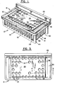
- FIG. 1 a magnetic separator 10 which includes an upper rack portion 12 and a lower base portion 14.
- Base portion 14 includes bottom 72 having associated therewith an array of magnets 46 (see Figures 7 and 8).
- Rack portion 12 includes top 24 having an array of apertures 32 therein, each aperture being sized to receive one container 34.
- the apertures can be numbered, e.g., from 1 to 60 beginning with the left hand, frontmost aperture.
- Containers 34 are typically open ended, 12x75 mm test tubes made of, for example, glass or polypropylene.
- Rack 12 mates with base 14 through movement of the rack in a generally vertical direction to bring a first portion 52 of each container 34 into the proximity of a north pole of one of magnets 46 and to bring a second portion 54 of each container 34 into the proximity of south pole of one of magnets 46 (see Figure 8).
- Rack 12 is most conveniently composed of upper portion 16 and lower portion 18 (see Figures 6 and 9), which portions can be combined by various standard techniques, such as, with screws and/or by gluing.
- the rack At the rear portion of top 24, the rack includes upwardly directed shoulder 26. This shoulder gives the rack a front-back orientation so that in use confusion does not arise with regard to which row of containers 34 is the front row and which row is the back row. Also, as described below, shoulder 26 serves to stabilize rack 12 when the rack is inverted during the decanting step of an immunoassay.
- each aperture 32 in top 24 has associated therewith one or more finger members 36 for engaging the sides of the containers.
- These finger members gently but firmly hold containers 34 in rack 12 so that the rack can be moved about by the user without any relative slippage between the containers and the rack.
- the finger members can include outwardly- extending protuberances 74 at their upper ends (see Figure 8).
- finger members 36 are molded as an integral part of top 24. In this way, dirt, spilled reagents and the like do not collect around apertures 32, as has been the case with prior art systems employing add-on plastic inserts, rather than integral fingers.
- top 24 Associated with opposite left and right hand ends of top 24 are downwardly directed legs 28.
- the distance from the bottoms 58 of legs 28 to the top of shoulder 26 is approximately equal to the heights of containers 34. As will now be described, this makes the rack self-supporting when inverted, even with only the frontmost row of apertures filled with containers.
- apertures 32 are filled one row at a time, beginning with the frontmost row. In some cases all the rows are filled; in other cases, only a few rows at the front of the rack are filled.
- Containers 34 are inserted into apertures 32 with rack 12 sitting on, for example, a table top. The containers are pushed downwardly against the restraining force of finger members 36 until the bottoms of the containers contact the surface of the table top. Because the distance from the bottoms 58 of legs 28 to the top of shoulder 26 is essentially equal to the height of containers 34, this puts the tops of containers 34 in essentially the same plane as the top of shoulder 26. Accordingly, when separator 10 is inverted, e.g., during decanting, it will support itself through contact of the top of shoulder 26 and the tops of containers 34 with, for example, a table top.
- Rack 12 also includes handle members 30 at opposite ends of top 24. As described below, these handle members mate with handle members 38 of base 14 to form a combined handle 68 for separator 10, which combined handle, when employed by the user, automatically results in rack 12 and base 14 being moved as a unit.
- legs 28 are conveniently made hollow, rather than solid. This makes rack 12 lighter and consumes less material, while still providing broad bottoms 58 for legs 28 so that rack 12 will set stably on a table top or the like.
- legs 28 include apertures 60 associated with their bottoms 58 and vents 62 associated with their tops for the ingress and egress of water to and from the interior of the leg.
- rack 12 includes two recesses 56 at opposite ends of top 24 for receiving the bottoms 58 of legs 28. As shown in Figure 6, recesses 56 are sized and configured to readily accept and hold the bottoms of legs 28.
- bottoms 58 of legs 28 also include recesses 64. These recesses are designed to mate with projections 66 formed in bottom 72 of base 14. The projections and recesses serve to guide rack 12 into the proper front-back alignment with respect to base 14 as the rack and the base are mated. As shown in Figures 6 and 9, recesses 64 have tapered sides to aid in this guiding and alignment process.
- base 14 the base is most conveniently composed of frame portion 20 and magnet cover 22 (see Figures 7 and 8).
- the frame portion and the magnet cover can be combined by various standard techniques, such as, by screws or other mechanical fasteners.
- a sealant or gasket (not shown) is used at the junction of frame portion 20 with magnetic cover 22 to prevent reagents or other fluids from entering the interior of base 14 and corroding magnets 46.
- Base 14 includes two handle members 38 at opposite ends of bottom 72.
- Each handle member includes a horizontal portion 40, which is grasped by the user, a vertical portion 42 and two side portions 44 (see Figure 2).
- handle members 38 are designed to mate with handle members 30 on rack 12 to form combined handles 68 for the entire separator 10.
- Horizontal portion 40 of handle member 38 closely engages the lower portion of handle member 30 so that when the user grasps combined handle 68, he perceives only a single handle and is not aware that there are actually two mechanically separate handles.
- the mating of rack 12 with base 14 can be done by moving rack 12 in a generally vertical direction, i.e., by simply setting the rack down onto the base, and yet the complete separator automatically moves as a unit when the combined handle is grasped by the user.
- Bottom 72 of base 14 has associated therewith an array of disc magnets 46.
- the magnets are arranged in lines or rows extending from the left-hand side to the right-hand side of base 14. These rows correspond to the rows of apertures 32 in top 24 of rack 12.
- the number of magnets in each row is equal to the number of apertures in a row plus one. All the magnets in a row are aligned with their north poles pointing in the same direction (see Figure 8). In this way, the mating of rack 12 with base 14 brings a first portion 52 of each container 34 into the proximity of a north pole of a magnet 46 and a second portion 54 of each container into the proximity of a south pole of a magnet 46.
- the magnets are held in upstanding rib members 50 which extend from the front to the back of the bottom 72 of base 14. These rib members include spacers 48 for holding magnets 46 in their respective rows (see Figure 7). In order to increase the strength of the magnetic fields within containers 34, rib members 50 have a reduced wall thickness in the regions 70 which are in closest proximity to containers 34 when rack 12 and base 14 are mated (see Figure 8).
- magnets 46 in base 14 is designed to minimize stray magnetic fields both below and throughout the space surrounding separator 10.
- magnets 46 are arranged with their axes parallel to bottom 72 of base 14. This places the strongest magnetic fields produced by the magnets in a plane parallel to the bottom of base 14, where those fields produce the desirable result of separating magnetically responsive particles from a surrounding medium, rather than the undesirable result of accidently attaching the separator to metallic structures.
- a magnetic shield is not required below the magnets, as was the case in the prior art commercial separator.
- the magnets are also arranged so that the north poles of the magnets in adjacent rows point in opposite directions.
- Figure 8 shows the orientation of the north poles for the magnets lying in an exemplary second row of magnets from the front of separator 10 (see section line in Figure 3). These magnets have their north poles pointing towards the left-hand side of the separator. In accordance with the preferred arrangement of the magnets, the magnets in the first and third rows will then have their north poles pointing towards the right-hand side of separator 10.
- the magnets at the ends of the rows do not all have the same orientation; that is, instead of being all north poles or all south poles, the magnets at the ends of the rows are alternately north pole, south pole, north pole, etc.
- This arrangement tends to cause the magnetic fields produced by the magnets at the ends of the rows to cancel each other out and thus reduce the net stray magnetic field produced in the space surrounding the right and left hand sides of separator 10.
- the stray magnetic fields along the front and back of separator 10 are generally small and confined to the region immediately around the magnets, so that overall the separator generates a minimum of stray magnetic fields.
- rack 12 and base 14 are each molded out of a plastic material.
- the plastic material For racks which are going to be subjected to boiling water for extended periods of time, the plastic material must be carefully chosen so that the molded parts will not deform or deteriorate during this treatment.
- the types of materials which can be used when boiling water treatment is contemplated include polyetherimides, polyethersulfones and polysulfones.
- Particularly preferred plastic materials for use with the present invention are polyetherimides.
- a polyetherimide sold the General Electric Company (Fairfield, Connecticut) under the trademark ULTEM (lot #1000-8102) has been found particularly suitable for use in constructing rack 12 and base 14.
- the separator is to be used only with immunoassays which do not require a boiling step, a variety of other plastic materials, including polypropylenes, impact-modified styrenes and medical grade ABS plastics, can be used. It should be noted that since base 14 is not normally subjected to boiling water treatment, it does not have to be composed of a plastic material which is resistent to boiling water, but rather a wider range of plastic materials can be used for this part of the separator.
- Magnets 46 can be of various types and grades.
- a particularly preferred magnet for use with the present invention is the INCOR 18 rare earth cobalt magnet manufactured by Electronic Memories & Magnetics Corp., Valparaiso, Indiana.
- the magnetically responsive particles can be used with the magnetic separator of the present invention.
- the magnetically responsive particles should have an average diameter in the submicron range so as to achieve the advantages of small particles described above.
- a suitable technique for obtaining such particles is described in U.S. Patent Application Serial No. 493,991, filed on May 12, 1983, in the names of Mark S. Chagnon, Ernest V. Groman, Lee Josephson and Roy A. Whitehead, the pertinent portions of which are incorporated herein by reference.
- the progress of the separation is easily monitored by the user by observing the change in turbidity of the aqueous solution, as well as the accumulation of particles in the regions of the poles of the magnets.
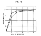
- the assay used was a radioimmunoassay for thyroid stimulating hormone (TSH).
- TSH thyroid stimulating hormone
- the magnetic particles and the procedures employed were those described in sections 7.10.2 and 7.12 of the above-referenced co-pending U.S. Patent Application Serial No. 493,991, the pertinent portions of which are incorporated herein by reference. Specifically, 500 microliters of magnetic particles were combined with 100 microliters of 125 1-rabbit anti-TSH antibody in phosphate buffered saline (Corning Medical and Scientific, No. 474185, Medfield, Mass.), and 100 microliters of a 60 pIU/ml TSH standard (Corning Medical and Scientific, No. 474186, Medfield, Mass.) in 12x75 mm test tubes. The mixture was incubated for 18 hours at room temperature, after which 500 microliters of water were added to each test tube to bring the total volume to 1.2 milliliters.
- the difference between the separation times achieved with the present invention and the prior art is even greater than that shown in Figure 10.
- the magnet arrangement of the present invention produces a distinct time advantage over the prior art arrangement for assay volumes greater than approximately 1.0 milliliter.
- the magnets need not be arranged with their poles aligned in transverse rows as illustrated herein, but can be arranged on the base portion of the separator in a variety of other configurations.
- the handles on the rack and the base can take a variety of configurations other than those shown and described herein.
Landscapes
- Sampling And Sample Adjustment (AREA)
- Investigating Or Analyzing Materials By The Use Of Magnetic Means (AREA)
Claims (9)
caractérisé en ce que les aimants (46) sont disposés avec leurs axes parallèles au fond de la base (14) afin de réduire les champs magnétiques de dispersion dans l'espace situé au-dessous de l'appareil (10), et le râtelier (12) et la base (14) s'adaptant l'un à l'autre pour placer une première partie de chaque conteneur (34) au voisinage d'un pôle nord d'un aimant (46) et une seconde partie de chaque conteneur (34) au voisinage d'un pôle sud d'un aimant (46).
Applications Claiming Priority (2)
| Application Number | Priority Date | Filing Date | Title |
|---|---|---|---|
| US53115883A | 1983-09-09 | 1983-09-09 | |
| US531158 | 1983-09-09 |
Publications (3)
| Publication Number | Publication Date |
|---|---|
| EP0136126A2 EP0136126A2 (fr) | 1985-04-03 |
| EP0136126A3 EP0136126A3 (en) | 1986-03-05 |
| EP0136126B1 true EP0136126B1 (fr) | 1989-06-14 |
Family
ID=24116497
Family Applications (1)
| Application Number | Title | Priority Date | Filing Date |
|---|---|---|---|
| EP19840306122 Expired EP0136126B1 (fr) | 1983-09-09 | 1984-09-07 | Séparateur magnétique pour immunoassay en phase solide |
Country Status (4)
| Country | Link |
|---|---|
| EP (1) | EP0136126B1 (fr) |
| JP (1) | JPS6067858A (fr) |
| CA (1) | CA1220168A (fr) |
| DE (1) | DE3478665D1 (fr) |
Cited By (5)
| Publication number | Priority date | Publication date | Assignee | Title |
|---|---|---|---|---|
| US6605213B1 (en) | 1998-05-01 | 2003-08-12 | Gen-Probe Incorporated | Method and apparatus for performing a magnetic separation purification procedure on a sample solution |
| US8361316B2 (en) | 1995-02-21 | 2013-01-29 | Sigris Research, Inc. | Device for mixing and separation of magnetic particles |
| TWI464400B (zh) * | 2013-07-03 | 2014-12-11 | Wistron Corp | 生醫檢測裝置 |
| WO2015088201A1 (fr) * | 2013-12-09 | 2015-06-18 | (주)바이오니아 | Dispositif de séparation de particules magnétiques et procédé de séparation et de purification d'acide nucléique ou de protéine l'utilisant |
| US9238226B2 (en) | 2009-12-10 | 2016-01-19 | Roche Molecular Systems, Inc. | Combo-tip rack |
Families Citing this family (50)
| Publication number | Priority date | Publication date | Assignee | Title |
|---|---|---|---|---|
| FI851702A0 (fi) * | 1985-04-29 | 1985-04-29 | Labsystems Oy | Foerfarande och anordning foer utfoering immunobestaemningar. |
| US4710472A (en) * | 1985-09-25 | 1987-12-01 | The United States Of America As Represented By The Secretary Of The Navy | Magnetic separation device |
| ATE108556T1 (de) * | 1987-11-16 | 1994-07-15 | Gene Trak Systems | Magnetische trennvorrichtung und verfahren zur anwendung in heterogenen prüfungen. |
| NO168811C (no) * | 1989-05-31 | 1992-04-08 | Dynal As | Separasjonsanordning for separering av magnetiserbare partikler |
| ATE154981T1 (de) * | 1990-04-06 | 1997-07-15 | Perkin Elmer Corp | Automatisiertes labor für molekularbiologie |
| DE4041080A1 (de) | 1990-12-21 | 1992-06-25 | Behringwerke Ag | Verfahren zur bestimmung eines analyten |
| US5395752A (en) * | 1993-03-19 | 1995-03-07 | Ciba Corning Diagnostics Corp. | Long emission wavelength chemiluminescent compounds and their use in test assays |
| DE59410037D1 (de) * | 1993-09-17 | 2002-03-14 | Hoffmann La Roche | Analysengerät mit einer Vorrichtung zum Abtrennen magnetischer Mikropartikel |
| DE4421058A1 (de) | 1994-06-16 | 1995-12-21 | Boehringer Mannheim Gmbh | Verfahren zur magnetischen Abtrennung von Flüssigkeitskomponenten |
| US5837144A (en) * | 1994-06-16 | 1998-11-17 | Boehringer Mannheim Gmbh | Method of magnetically separating liquid components |
| DE4429155A1 (de) | 1994-08-17 | 1996-02-22 | Hans Schiesl | Meßanordnung und Verfahren zur Durchführung luminometrischer Reihenanalysen sowie Mehrfachküvette zur Aufnahme von Flüssigkeitsproben hierfür |
| US5571481A (en) * | 1995-02-17 | 1996-11-05 | Vicam, L.P. | Magnetic capture rack with slidable magnetic member |
| US20030127396A1 (en) * | 1995-02-21 | 2003-07-10 | Siddiqi Iqbal Waheed | Apparatus and method for processing magnetic particles |
| ATE446141T1 (de) | 1997-11-14 | 2009-11-15 | Gen Probe Inc | Arbeitsgerät zur analyse |
| US5993745A (en) * | 1998-03-04 | 1999-11-30 | Roche Diagnostics Corporation | Archival storage tray for multiple test tubes |
| US8337753B2 (en) | 1998-05-01 | 2012-12-25 | Gen-Probe Incorporated | Temperature-controlled incubator having a receptacle mixing mechanism |
| US6019225A (en) * | 1998-10-26 | 2000-02-01 | Matrix Technologies Corp. | Pipette tip rack with array of interconnected sleeves |
| EP3718635A1 (fr) | 2003-07-31 | 2020-10-07 | Handylab, Inc. | Traitement d'échantillons contenant des particules |
| FI20031635A0 (fi) | 2003-11-11 | 2003-11-11 | Thermo Electron Oy | Partikkelien erotusväline |
| FR2863626B1 (fr) * | 2003-12-15 | 2006-08-04 | Commissariat Energie Atomique | Procede et dispositif de division d'un echantillon biologique par effet magnetique |
| US8852862B2 (en) | 2004-05-03 | 2014-10-07 | Handylab, Inc. | Method for processing polynucleotide-containing samples |
| US7964413B2 (en) | 2005-03-10 | 2011-06-21 | Gen-Probe Incorporated | Method for continuous mode processing of multiple reaction receptacles in a real-time amplification assay |
| JP4837410B2 (ja) * | 2006-03-22 | 2011-12-14 | 富士フイルム株式会社 | 標的化合物の検出方法 |
| US10900066B2 (en) | 2006-03-24 | 2021-01-26 | Handylab, Inc. | Microfluidic system for amplifying and detecting polynucleotides in parallel |
| ES2692380T3 (es) | 2006-03-24 | 2018-12-03 | Handylab, Inc. | Método para realizar PCR con un cartucho con varias pistas |
| US11806718B2 (en) | 2006-03-24 | 2023-11-07 | Handylab, Inc. | Fluorescence detector for microfluidic diagnostic system |
| US7998708B2 (en) | 2006-03-24 | 2011-08-16 | Handylab, Inc. | Microfluidic system for amplifying and detecting polynucleotides in parallel |
| WO2008060604A2 (fr) | 2006-11-14 | 2008-05-22 | Handylab, Inc. | Système microfluidique utilisé pour amplifier et détecter des polynucléotides en parallèle |
| US8765076B2 (en) | 2006-11-14 | 2014-07-01 | Handylab, Inc. | Microfluidic valve and method of making same |
| US9199247B2 (en) | 2007-05-29 | 2015-12-01 | Invitrogen Dynal As | Magnetic separation rack |
| GB0724404D0 (en) | 2007-05-29 | 2008-01-30 | Invitrogen Dynal As | A sample vessel retaining portion |
| US8287820B2 (en) | 2007-07-13 | 2012-10-16 | Handylab, Inc. | Automated pipetting apparatus having a combined liquid pump and pipette head system |
| AU2008276211B2 (en) | 2007-07-13 | 2015-01-22 | Handylab, Inc. | Polynucleotide capture materials, and methods of using same |
| US8105783B2 (en) | 2007-07-13 | 2012-01-31 | Handylab, Inc. | Microfluidic cartridge |
| AU2013205254B8 (en) * | 2007-07-13 | 2015-10-29 | Handylab, Inc. | Integrated apparatus for performing nucleic acid extraction and diagnostic testing on multiple biological samples |
| US9186677B2 (en) | 2007-07-13 | 2015-11-17 | Handylab, Inc. | Integrated apparatus for performing nucleic acid extraction and diagnostic testing on multiple biological samples |
| US8182763B2 (en) | 2007-07-13 | 2012-05-22 | Handylab, Inc. | Rack for sample tubes and reagent holders |
| US8268264B2 (en) | 2009-02-09 | 2012-09-18 | Caprotec Bioanalytics Gmbh | Devices, systems and methods for separating magnetic particles |
| DE102009027454A1 (de) * | 2009-07-03 | 2011-01-05 | Robert Bosch Gmbh | Aufnahmebehälter für pharmazeutische Behältnisse |
| US9046507B2 (en) | 2010-07-29 | 2015-06-02 | Gen-Probe Incorporated | Method, system and apparatus for incorporating capacitive proximity sensing in an automated fluid transfer procedure |
| EP2678664B1 (fr) | 2011-02-24 | 2019-08-07 | Gen-Probe Incorporated | Systèmes et procédés de distinction de signaux optiques de différentes fréquences de modulation dans un détecteur de signaux optiques |
| JP6088487B2 (ja) | 2011-04-15 | 2017-03-01 | ベクトン・ディキンソン・アンド・カンパニーBecton, Dickinson And Company | 走査リアルタイムマイクロ流体熱サイクラーと同期熱サイクリング及び走査光学検出の方法 |
| JP6072033B2 (ja) * | 2011-07-29 | 2017-02-01 | コーニング インコーポレイテッド | 磁気分離装置及び方法 |
| WO2013067202A1 (fr) | 2011-11-04 | 2013-05-10 | Handylab, Inc. | Dispositif de préparation d'échantillons de polynucléotides |
| GB201208547D0 (en) | 2012-05-15 | 2012-06-27 | Life Technologies As | Sample holder |
| JP5974230B2 (ja) * | 2012-07-12 | 2016-08-23 | 多摩川精機株式会社 | 磁気スタンド |
| US11179296B2 (en) | 2015-09-04 | 2021-11-23 | Daikyo Seiko, Ltd. | Container holding member and medical container set |
| EP3887052A1 (fr) | 2018-11-28 | 2021-10-06 | Corning Incorporated | Plateau de pointe de pipette et ensemble portoir |
| CN111440702A (zh) * | 2020-05-26 | 2020-07-24 | 珠海圣美生物诊断技术有限公司 | 样品架和样品处理设备 |
| JP2024069923A (ja) * | 2022-11-10 | 2024-05-22 | 株式会社日立ハイテク | 試験管ラック用治具 |
Family Cites Families (9)
| Publication number | Priority date | Publication date | Assignee | Title |
|---|---|---|---|---|
| US3796879A (en) * | 1972-03-24 | 1974-03-12 | Searle & Co | Automated multiple sample processing for well type radioactivity counters |
| JPS5413107Y2 (fr) * | 1973-11-13 | 1979-06-05 | ||
| US3933997A (en) * | 1974-03-01 | 1976-01-20 | Corning Glass Works | Solid phase radioimmunoassay of digoxin |
| US3985649A (en) * | 1974-11-25 | 1976-10-12 | Eddelman Roy T | Ferromagnetic separation process and material |
| US3970518A (en) * | 1975-07-01 | 1976-07-20 | General Electric Company | Magnetic separation of biological particles |
| US4090850A (en) * | 1976-11-01 | 1978-05-23 | E. R. Squibb & Sons, Inc. | Apparatus for use in radioimmunoassays |
| US4219411A (en) * | 1978-09-18 | 1980-08-26 | California Institute Of Technology | Cell sorting apparatus |
| DE3070333D1 (en) * | 1979-11-13 | 1985-04-25 | Technicon Instr | Test-tube assembly, kit for making it and method of manual immunoassay |
| DE3102029A1 (de) * | 1981-01-22 | 1982-08-26 | Europäisches Laboratorium für Molekularbiologie (EMBL), 6900 Heidelberg | Vorrichtung zum abtrennen ferromagnetischer partikel |
-
1984
- 1984-05-08 CA CA000453810A patent/CA1220168A/fr not_active Expired
- 1984-07-04 JP JP13887484A patent/JPS6067858A/ja active Granted
- 1984-09-07 EP EP19840306122 patent/EP0136126B1/fr not_active Expired
- 1984-09-07 DE DE8484306122T patent/DE3478665D1/de not_active Expired
Cited By (12)
| Publication number | Priority date | Publication date | Assignee | Title |
|---|---|---|---|---|
| US8361316B2 (en) | 1995-02-21 | 2013-01-29 | Sigris Research, Inc. | Device for mixing and separation of magnetic particles |
| US6605213B1 (en) | 1998-05-01 | 2003-08-12 | Gen-Probe Incorporated | Method and apparatus for performing a magnetic separation purification procedure on a sample solution |
| US6764649B2 (en) | 1998-05-01 | 2004-07-20 | Gen-Probe Incorporated | Transport mechanism |
| US6890742B2 (en) | 1998-05-01 | 2005-05-10 | Gen-Probe Incorporated | Automated process for isolating and amplifying a target nucleic acid sequence |
| US7033820B2 (en) | 1998-05-01 | 2006-04-25 | Gen-Probe Incorporated | Automated system for isolating and amplifying a target nucleic acid sequence |
| US7135145B2 (en) | 1998-05-01 | 2006-11-14 | Gen-Probe Incorporated | Device for agitating the fluid contents of a container |
| US7267795B2 (en) | 1998-05-01 | 2007-09-11 | Gen-Probe Incorporated | Incubator for use in an automated diagnostic analyzer |
| US7384600B2 (en) | 1998-05-01 | 2008-06-10 | Gen-Probe Incorporated | Multiple ring assembly for providing specimen to reaction receptacles within an automated analyzer |
| US9238226B2 (en) | 2009-12-10 | 2016-01-19 | Roche Molecular Systems, Inc. | Combo-tip rack |
| TWI464400B (zh) * | 2013-07-03 | 2014-12-11 | Wistron Corp | 生醫檢測裝置 |
| WO2015088201A1 (fr) * | 2013-12-09 | 2015-06-18 | (주)바이오니아 | Dispositif de séparation de particules magnétiques et procédé de séparation et de purification d'acide nucléique ou de protéine l'utilisant |
| US10441957B2 (en) | 2013-12-09 | 2019-10-15 | Bioneer Corporation | Magnetic particle separating device, and method of separating and purifying nucleic acid or protein using same |
Also Published As
| Publication number | Publication date |
|---|---|
| JPH0522181B2 (fr) | 1993-03-26 |
| EP0136126A2 (fr) | 1985-04-03 |
| JPS6067858A (ja) | 1985-04-18 |
| CA1220168A (fr) | 1987-04-07 |
| EP0136126A3 (en) | 1986-03-05 |
| DE3478665D1 (en) | 1989-07-20 |
Similar Documents
| Publication | Publication Date | Title |
|---|---|---|
| EP0136126B1 (fr) | Séparateur magnétique pour immunoassay en phase solide | |
| CA1152559A (fr) | Dosage immunologique et appareil a cette fin | |
| EP0358948B1 (fr) | Méthode pour effectuer automatiquement des réactifs magnétiques en phase solide | |
| US5795470A (en) | Magnetic separation apparatus | |
| US4895650A (en) | Magnetic separation rack for diagnostic assays | |
| US5318914A (en) | Process and magnetic device for immunological analysis of a solid phase | |
| EP0296724B1 (fr) | Essai et dispositif utilisant une membrane non-buvant permettant un courant latéral | |
| AU706911B2 (en) | Multisample magnetic separation device | |
| US5985153A (en) | Magnetic separation apparatus and methods employing an internal magnetic capture gradient and an external transport force | |
| EP0593480B1 (fr) | Appareil et procede de separation magnetique | |
| US5837144A (en) | Method of magnetically separating liquid components | |
| US8852958B2 (en) | Magnetic immunodiagnostic method for the demonstration of antibody/antigen complexes especially of blood groups | |
| US20080206099A1 (en) | Magnetic separator and analyzer using the same | |
| JPH0829425A (ja) | 液体中の被検成分を磁気的に分離する方法 | |
| WO1997046882A9 (fr) | Separation magnetique au moyen de gradients externes et internes | |
| JPH01201156A (ja) | 磁気的分離デバイスおよび不均質検定における使用法 | |
| EP0631669A1 (fr) | Tests de liaison fondes sur le magnetisme et mettant en oeuvre des elements de liaison marques magnetiquement | |
| JP4964161B2 (ja) | 磁性粒子を用いた分析方法 | |
| US20110207151A1 (en) | Utilisation de ferrofluides pour le phenotypage sanguin et applications derivees | |
| US20110287555A1 (en) | Reusable sheaths for separating magnetic particles | |
| EP1151271A1 (fr) | Methode et dispositif permettant de separer des matieres biologiques et autres substances |
Legal Events
| Date | Code | Title | Description |
|---|---|---|---|
| PUAI | Public reference made under article 153(3) epc to a published international application that has entered the european phase |
Free format text: ORIGINAL CODE: 0009012 |
|
| AK | Designated contracting states |
Designated state(s): DE FR GB IT |
|
| PUAL | Search report despatched |
Free format text: ORIGINAL CODE: 0009013 |
|
| AK | Designated contracting states |
Kind code of ref document: A3 Designated state(s): DE FR GB IT |
|
| 17P | Request for examination filed |
Effective date: 19860807 |
|
| 17Q | First examination report despatched |
Effective date: 19871210 |
|
| GRAA | (expected) grant |
Free format text: ORIGINAL CODE: 0009210 |
|
| AK | Designated contracting states |
Kind code of ref document: B1 Designated state(s): DE FR GB IT |
|
| ITF | It: translation for a ep patent filed | ||
| REF | Corresponds to: |
Ref document number: 3478665 Country of ref document: DE Date of ref document: 19890720 |
|
| ET | Fr: translation filed | ||
| PLBE | No opposition filed within time limit |
Free format text: ORIGINAL CODE: 0009261 |
|
| STAA | Information on the status of an ep patent application or granted ep patent |
Free format text: STATUS: NO OPPOSITION FILED WITHIN TIME LIMIT |
|
| 26N | No opposition filed | ||
| ITTA | It: last paid annual fee | ||
| PGFP | Annual fee paid to national office [announced via postgrant information from national office to epo] |
Ref country code: GB Payment date: 19970804 Year of fee payment: 14 |
|
| PGFP | Annual fee paid to national office [announced via postgrant information from national office to epo] |
Ref country code: FR Payment date: 19970905 Year of fee payment: 14 |
|
| PGFP | Annual fee paid to national office [announced via postgrant information from national office to epo] |
Ref country code: DE Payment date: 19970930 Year of fee payment: 14 |
|
| PG25 | Lapsed in a contracting state [announced via postgrant information from national office to epo] |
Ref country code: GB Free format text: LAPSE BECAUSE OF NON-PAYMENT OF DUE FEES Effective date: 19980907 |
|
| GBPC | Gb: european patent ceased through non-payment of renewal fee |
Effective date: 19980907 |
|
| PG25 | Lapsed in a contracting state [announced via postgrant information from national office to epo] |
Ref country code: FR Free format text: LAPSE BECAUSE OF NON-PAYMENT OF DUE FEES Effective date: 19990531 |
|
| PG25 | Lapsed in a contracting state [announced via postgrant information from national office to epo] |
Ref country code: DE Free format text: LAPSE BECAUSE OF NON-PAYMENT OF DUE FEES Effective date: 19990701 |
|
| REG | Reference to a national code |
Ref country code: FR Ref legal event code: ST |