EP0136127A2 - Echangeur tubulaire à enveloppe - Google Patents
Echangeur tubulaire à enveloppe Download PDFInfo
- Publication number
- EP0136127A2 EP0136127A2 EP84306126A EP84306126A EP0136127A2 EP 0136127 A2 EP0136127 A2 EP 0136127A2 EP 84306126 A EP84306126 A EP 84306126A EP 84306126 A EP84306126 A EP 84306126A EP 0136127 A2 EP0136127 A2 EP 0136127A2
- Authority
- EP
- European Patent Office
- Prior art keywords
- tube
- tube plate
- tubes
- normal
- heat exchanger
- Prior art date
- Legal status (The legal status is an assumption and is not a legal conclusion. Google has not performed a legal analysis and makes no representation as to the accuracy of the status listed.)
- Granted
Links
- 238000007789 sealing Methods 0.000 claims abstract description 7
- 238000003466 welding Methods 0.000 claims description 8
- 239000002360 explosive Substances 0.000 claims description 4
- 238000012544 monitoring process Methods 0.000 claims description 2
- 229910001338 liquidmetal Inorganic materials 0.000 description 8
- 239000012530 fluid Substances 0.000 description 4
- XKRFYHLGVUSROY-UHFFFAOYSA-N Argon Chemical compound [Ar] XKRFYHLGVUSROY-UHFFFAOYSA-N 0.000 description 2
- 238000005219 brazing Methods 0.000 description 2
- 239000007789 gas Substances 0.000 description 2
- XLYOFNOQVPJJNP-UHFFFAOYSA-N water Substances O XLYOFNOQVPJJNP-UHFFFAOYSA-N 0.000 description 2
- 229910052786 argon Inorganic materials 0.000 description 1
- 230000000903 blocking effect Effects 0.000 description 1
- 238000006243 chemical reaction Methods 0.000 description 1
- 238000010276 construction Methods 0.000 description 1
- 230000008602 contraction Effects 0.000 description 1
- 230000008878 coupling Effects 0.000 description 1
- 238000010168 coupling process Methods 0.000 description 1
- 238000005859 coupling reaction Methods 0.000 description 1
- 230000007547 defect Effects 0.000 description 1
- 230000004927 fusion Effects 0.000 description 1
- 231100001261 hazardous Toxicity 0.000 description 1
- 239000011261 inert gas Substances 0.000 description 1
- 238000005304 joining Methods 0.000 description 1
- 238000004519 manufacturing process Methods 0.000 description 1
- 239000002184 metal Substances 0.000 description 1
- 238000005070 sampling Methods 0.000 description 1
- 230000035939 shock Effects 0.000 description 1
- 125000006850 spacer group Chemical group 0.000 description 1
Images

Classifications
-
- F—MECHANICAL ENGINEERING; LIGHTING; HEATING; WEAPONS; BLASTING
- F28—HEAT EXCHANGE IN GENERAL
- F28F—DETAILS OF HEAT-EXCHANGE AND HEAT-TRANSFER APPARATUS, OF GENERAL APPLICATION
- F28F9/00—Casings; Header boxes; Auxiliary supports for elements; Auxiliary members within casings
- F28F9/02—Header boxes; End plates
- F28F9/0229—Double end plates; Single end plates with hollow spaces
-
- F—MECHANICAL ENGINEERING; LIGHTING; HEATING; WEAPONS; BLASTING
- F22—STEAM GENERATION
- F22B—METHODS OF STEAM GENERATION; STEAM BOILERS
- F22B1/00—Methods of steam generation characterised by form of heating method
- F22B1/02—Methods of steam generation characterised by form of heating method by exploitation of the heat content of hot heat carriers
- F22B1/06—Methods of steam generation characterised by form of heating method by exploitation of the heat content of hot heat carriers the heat carrier being molten; Use of molten metal, e.g. zinc, as heat transfer medium
- F22B1/063—Methods of steam generation characterised by form of heating method by exploitation of the heat content of hot heat carriers the heat carrier being molten; Use of molten metal, e.g. zinc, as heat transfer medium for metal cooled nuclear reactors
Definitions
- This invention relates to tube-in-shell heat exchangers.
- double sealing joints between the tubes and a tube plate manifest by a secondary tube plate adjacent to but spaced from the normal tube plate, each tube extending through the secondary tube plate and being sealed thereto as well as being sealingly secured to the normal tube plate, and the secondary tube plate being sealed in its spaced position by a bellows sealingly secured to both the normal and the secondary tube plates and disposed so as to envelope the said tubes.
- the space between the normal and secondary tube plates can be employed for monitoring for leakage.
- the joints between the tubes and the normal tube plate can be by explosive welding or by welding of each tube to a pintle depending from each bore in the tube plate.
- the joints between the tubes and the secondary tube plate can be by brazing, with or without the provision of pintles provided on the outer surface of the secondary tube plate.
- a feature of the invention is that the secondary tube plate is not rigidly connected to the main tube plate (as in the heat exchanger disclosed in British Patent No 785 862).
- the bellows not only serves to seal the space between the main and secondary tube plates but also allows some degree of relative movement to take place between the tube plates by virtue of bellows deflection. In this way, axial loading of the tube-to-plate joints in response to thermal shocks causing differential expansion or contraction is substantially reduced.
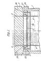
- a tube-in-shell heat exchanger which is of U-form, the upper end of one limb only being shown in Figure 1, the upper end of the other limb being similar.
- the heat exchanger has a casing 1 secured by welding to a tube plate 2 which has a plurality, for example over 900, of bores 3 (2 only of which are shown but the axis of others being indicated in dot-and-dash lines), each bore containing a tube 4 of the heat exchanger, each tube 4 being sealingly secured to the tube plate 2, for example by explosive welding at the region designated 5 in Figure 2, or alternatively by fusion welding 6 to a pintle 7 provided at the lower surface of the tube plate 2 and indicated in dot-and-dash lines in Figure 2.
- a secondary tube plate 8 is disposed beneath the normal tube plate 2 and spaced significantly therefrom, and having bores 9 corresponding with the bores 3 of tube plate 2.
- Each tube 4 extends through a bore 9 and is secured to the secondary tube plate 8 by brazing.
- a pintle 10 depending from the tube plate 8 and continuing each bore 9 so as to facilitate the production of the brazed sealing joints. These are indicated by the regions of brazed metal 11 and the expanded part 12 of the relevant tube 4.
- the normal tube plate 2 has a depending flange 13 of sufficient diameter to embrace all the tubes 4 associated with the tube plate 2.
- a ring 15 itself secured by welding at 16 to a bellows 17 which extends downwardly sufficiently to enclose the said space beneath the tube plate and above the secondary tube plate 8, being secured by welding at 18 to a ring 19 itself welded at 20 to a depending rim 21 of the secondary tube plate 8.
- the space between the two tube plates, designated 22, is conveniently occupied by a clean inert gas such as Argon and an inclined bore 23 serves not only for maintaining the space 22 at a slight positive pressure but also for enabling sampling of the gas in space 22 for testing it for a change of composition which would indicate that there was a defect in one of the sealing joints,it being inconceivable that liquid metal could penetrate into this region other than by catastrophic failure.
- Further inclined holes 24 extend through the tube plate 2 and communicate with the space outside the bellows but within the casing and above the liquid metal 4, indicated by reference 25 in Figure 1.
- a tube spacer plate 26 can be provided beneath the secondary tube plate 8 and secured to the tube plate 2 by depending columns 27.
- the invention provides greater reliability and a greater safety margin by isolating the normal tube to tube plate joints from the hazardous liquid metal environment by means of the provision of the secondary tube plate.
Landscapes
- Engineering & Computer Science (AREA)
- Physics & Mathematics (AREA)
- Thermal Sciences (AREA)
- Mechanical Engineering (AREA)
- General Engineering & Computer Science (AREA)
- High Energy & Nuclear Physics (AREA)
- Life Sciences & Earth Sciences (AREA)
- Sustainable Development (AREA)
- Sustainable Energy (AREA)
- Heat-Exchange Devices With Radiators And Conduit Assemblies (AREA)
- Details Of Heat-Exchange And Heat-Transfer (AREA)
Applications Claiming Priority (2)
| Application Number | Priority Date | Filing Date | Title |
|---|---|---|---|
| GB8325948 | 1983-09-28 | ||
| GB08325948A GB2147403B (en) | 1983-09-28 | 1983-09-28 | Tube-in-shell heat exchangers |
Publications (3)
| Publication Number | Publication Date |
|---|---|
| EP0136127A2 true EP0136127A2 (fr) | 1985-04-03 |
| EP0136127A3 EP0136127A3 (en) | 1985-12-18 |
| EP0136127B1 EP0136127B1 (fr) | 1988-03-09 |
Family
ID=10549406
Family Applications (1)
| Application Number | Title | Priority Date | Filing Date |
|---|---|---|---|
| EP84306126A Expired EP0136127B1 (fr) | 1983-09-28 | 1984-09-07 | Echangeur tubulaire à enveloppe |
Country Status (5)
| Country | Link |
|---|---|
| US (1) | US4640343A (fr) |
| EP (1) | EP0136127B1 (fr) |
| JP (1) | JPS6093296A (fr) |
| DE (2) | DE136127T1 (fr) |
| GB (1) | GB2147403B (fr) |
Cited By (2)
| Publication number | Priority date | Publication date | Assignee | Title |
|---|---|---|---|---|
| FR2683897A1 (fr) * | 1991-11-19 | 1993-05-21 | Framatome Sa | Echangeur de chaleur a tubes droits perfectionne dans lequel circule un fluide a temperature elevee et variable. |
| EP1014026A3 (fr) * | 1998-12-23 | 2001-08-22 | L'air Liquide, Societe Anonyme Pour L'etude Et L'exploitation Des Procedes Georges Claude | Echangeur de chaleur pour préchauffer un gaz oxydant |
Families Citing this family (5)
| Publication number | Priority date | Publication date | Assignee | Title |
|---|---|---|---|---|
| SE511440C2 (sv) | 1997-05-28 | 1999-09-27 | Sandvik Ab | Värmeväxlare med rör hängande ned i en dubbelväggig, kyld och bälgförsedd tubplatta, samt tubplatta för rörvärmeväxlare |
| DE50214106D1 (de) * | 2001-10-24 | 2010-01-28 | Behr Gmbh & Co Kg | Wärmeübertrager |
| JP2008122248A (ja) * | 2006-11-13 | 2008-05-29 | Toshiba Corp | 高速炉 |
| US9109614B1 (en) * | 2011-03-04 | 2015-08-18 | Lightsail Energy, Inc. | Compressed gas energy storage system |
| US9036986B2 (en) | 2012-03-21 | 2015-05-19 | Bruce Amberson | Heater |
Family Cites Families (18)
| Publication number | Priority date | Publication date | Assignee | Title |
|---|---|---|---|---|
| DE13601C (de) * | C. ZIEGLER in Nippes bei Cöln | Neuerung an der Befestigung der Reifen auf Rädern der Eisenbahnfuhrwerke | ||
| FR650058A (fr) * | 1928-02-09 | 1929-01-04 | Delas Condenseurs | Dispositif pour éviter les mélanges de fluides dans les échangeurs thermiques à faisceau tubulaire |
| US2152266A (en) * | 1937-05-14 | 1939-03-28 | Andale Co | Heat exchange equipment |
| US2658728A (en) * | 1948-06-25 | 1953-11-10 | Lummus Co | Method of detecting leakage between heat transfer fluids |
| NL101229C (fr) * | 1955-02-08 | |||
| GB790704A (en) * | 1955-08-16 | 1958-02-12 | Serck Radiators Ltd | Tubular heat exchange apparatus |
| GB842530A (en) * | 1958-01-04 | 1960-07-27 | Rosenblads Patenter Ab | Improvements in or relating to an arrangement in indirect heat exchangers |
| GB984373A (en) * | 1962-06-21 | 1965-02-24 | Parsons C A & Co Ltd | Improvements in and relating to tubular heat exchangers |
| US4171014A (en) * | 1972-11-28 | 1979-10-16 | Sulzer Brothers Limited | Arrangement for mounting tubes in a tank wall |
| DE2327842A1 (de) * | 1973-06-01 | 1974-12-19 | Prvni Brnenska Strojirna | Hochdruckwaermetauscher |
| SU664010A1 (ru) * | 1977-01-03 | 1979-05-25 | Предприятие П/Я А-3513 | Теплообменник |
| GB1585045A (en) * | 1977-06-28 | 1981-02-18 | Westinghouse Electric Corp | Heat exchanger with double walled tubes |
| US4117966A (en) * | 1977-10-13 | 1978-10-03 | The United States Of America As Represented By The United States Department Of Energy | Explosive welding of a tube into a tube sheet |
| CH630718A5 (de) * | 1978-02-13 | 1982-06-30 | Agresto Ag International Sa | Rohrbuendelwaermeaustauscher. |
| US4249593A (en) * | 1979-01-19 | 1981-02-10 | The United States Of America As Represented By The United States Department Of Energy | Heat exchanger with leak detecting double wall tubes |
| US4252182A (en) * | 1979-03-20 | 1981-02-24 | Ecolaire Incorporated | Tube sheet shield |
| US4237968A (en) * | 1979-05-02 | 1980-12-09 | Westinghouse Electric Corp. | Heat exchanger with double wall tubes and three tube sheets |
| FR2499212A1 (fr) * | 1981-02-02 | 1982-08-06 | Commissariat Energie Atomique | Dispositif de protection de la plaque tubulaire a l'extremite chaude d'un echangeur de chaleur vertical |
-
1983
- 1983-09-28 GB GB08325948A patent/GB2147403B/en not_active Expired
-
1984
- 1984-09-07 DE DE198484306126T patent/DE136127T1/de active Pending
- 1984-09-07 DE DE8484306126T patent/DE3469796D1/de not_active Expired
- 1984-09-07 EP EP84306126A patent/EP0136127B1/fr not_active Expired
- 1984-09-12 US US06/649,669 patent/US4640343A/en not_active Expired - Fee Related
- 1984-09-19 JP JP59196515A patent/JPS6093296A/ja active Pending
Cited By (2)
| Publication number | Priority date | Publication date | Assignee | Title |
|---|---|---|---|---|
| FR2683897A1 (fr) * | 1991-11-19 | 1993-05-21 | Framatome Sa | Echangeur de chaleur a tubes droits perfectionne dans lequel circule un fluide a temperature elevee et variable. |
| EP1014026A3 (fr) * | 1998-12-23 | 2001-08-22 | L'air Liquide, Societe Anonyme Pour L'etude Et L'exploitation Des Procedes Georges Claude | Echangeur de chaleur pour préchauffer un gaz oxydant |
Also Published As
| Publication number | Publication date |
|---|---|
| GB2147403A (en) | 1985-05-09 |
| JPS6093296A (ja) | 1985-05-25 |
| GB8325948D0 (en) | 1983-11-23 |
| DE3469796D1 (en) | 1988-04-14 |
| EP0136127B1 (fr) | 1988-03-09 |
| US4640343A (en) | 1987-02-03 |
| EP0136127A3 (en) | 1985-12-18 |
| GB2147403B (en) | 1987-05-07 |
| DE136127T1 (de) | 1985-08-14 |
Similar Documents
| Publication | Publication Date | Title |
|---|---|---|
| US4216821A (en) | Pump/heat exchanger | |
| US4192374A (en) | Heat exchangers | |
| US4332401A (en) | Insulated casing assembly | |
| US3655224A (en) | Multi-ply bellows structure with fluid pervious spacer | |
| US4182408A (en) | Multilayered tube sheet assembly for heat exchangers | |
| EP0136127B1 (fr) | Echangeur tubulaire à enveloppe | |
| US3465727A (en) | Steam generator and method of making the same | |
| US4182407A (en) | Tube sheet comprising two interspaced sheet members and heat exchanger comprising at least one such tube sheet | |
| US2956704A (en) | Removable tube sheet construction for heat exchangers | |
| US4547944A (en) | Tube-in-shell heat exchangers | |
| EP0110707B1 (fr) | Echangeurs de chaleur du type "tubes-dans-enveloppe" | |
| US4612976A (en) | Steam generator for a nuclear reactor cooled with liquid metal | |
| GB2079204A (en) | Methods of Securing a Tube in the Bore of a Wall | |
| US5167907A (en) | Process for plugging a tube of a straight-tube heat exchanger | |
| JPS61139737A (ja) | フランジ継手の漏洩防止装置 | |
| WO1996005493A1 (fr) | Joint de transition soude par explosion pour multiplicateur de pression | |
| JPS62209293A (ja) | 配管用伸縮継手 | |
| JPS5844199B2 (ja) | 溶接による盲栓が可能な多管式熱交換器 | |
| CN223393456U (zh) | 复合板塔 | |
| JPH0440637B2 (fr) | ||
| JPS60200096A (ja) | 熱交換器伝熱管の盲栓法 | |
| KR100494879B1 (ko) | 화공유체용 탱크의 용접선의 누설 차단구조 | |
| JPH0240958B2 (fr) | ||
| JPS5945868B2 (ja) | 高温用シ−ル構造 | |
| WO1990015418A1 (fr) | Procede de reparation de parties de systeme d'un reacteur nucleaire, en contact avec le milieu de traitement |
Legal Events
| Date | Code | Title | Description |
|---|---|---|---|
| PUAI | Public reference made under article 153(3) epc to a published international application that has entered the european phase |
Free format text: ORIGINAL CODE: 0009012 |
|
| AK | Designated contracting states |
Designated state(s): DE FR IT |
|
| ITCL | It: translation for ep claims filed |
Representative=s name: JACOBACCI CASETTA & PERANI S.P.A. |
|
| EL | Fr: translation of claims filed | ||
| DET | De: translation of patent claims | ||
| PUAL | Search report despatched |
Free format text: ORIGINAL CODE: 0009013 |
|
| AK | Designated contracting states |
Designated state(s): DE FR IT |
|
| 17P | Request for examination filed |
Effective date: 19860218 |
|
| 17Q | First examination report despatched |
Effective date: 19861024 |
|
| GRAA | (expected) grant |
Free format text: ORIGINAL CODE: 0009210 |
|
| AK | Designated contracting states |
Kind code of ref document: B1 Designated state(s): DE FR IT |
|
| ITF | It: translation for a ep patent filed | ||
| REF | Corresponds to: |
Ref document number: 3469796 Country of ref document: DE Date of ref document: 19880414 |
|
| ET | Fr: translation filed | ||
| PLBE | No opposition filed within time limit |
Free format text: ORIGINAL CODE: 0009261 |
|
| STAA | Information on the status of an ep patent application or granted ep patent |
Free format text: STATUS: NO OPPOSITION FILED WITHIN TIME LIMIT |
|
| 26N | No opposition filed | ||
| PG25 | Lapsed in a contracting state [announced via postgrant information from national office to epo] |
Ref country code: FR Effective date: 19900531 |
|
| PG25 | Lapsed in a contracting state [announced via postgrant information from national office to epo] |
Ref country code: DE Effective date: 19900601 |
|
| REG | Reference to a national code |
Ref country code: FR Ref legal event code: ST |