EP0136156A2 - Elektrischer Verbinder - Google Patents
Elektrischer Verbinder Download PDFInfo
- Publication number
- EP0136156A2 EP0136156A2 EP84306423A EP84306423A EP0136156A2 EP 0136156 A2 EP0136156 A2 EP 0136156A2 EP 84306423 A EP84306423 A EP 84306423A EP 84306423 A EP84306423 A EP 84306423A EP 0136156 A2 EP0136156 A2 EP 0136156A2
- Authority
- EP
- European Patent Office
- Prior art keywords
- housing
- coupler
- head
- electric coupler
- cable
- Prior art date
- Legal status (The legal status is an assumption and is not a legal conclusion. Google has not performed a legal analysis and makes no representation as to the accuracy of the status listed.)
- Granted
Links
- 239000002184 metal Substances 0.000 claims abstract description 29
- 229910052751 metal Inorganic materials 0.000 claims abstract description 29
- 239000004020 conductor Substances 0.000 claims abstract description 20
- 239000004033 plastic Substances 0.000 claims abstract description 15
- 229920003023 plastic Polymers 0.000 claims abstract description 15
- 150000001875 compounds Chemical class 0.000 claims abstract description 7
- 239000012777 electrically insulating material Substances 0.000 claims abstract description 3
- 238000012216 screening Methods 0.000 claims description 6
- 239000000463 material Substances 0.000 claims description 5
- 230000000063 preceeding effect Effects 0.000 claims 3
- 229920005989 resin Polymers 0.000 description 4
- 239000011347 resin Substances 0.000 description 4
- 229910001369 Brass Inorganic materials 0.000 description 3
- 239000010951 brass Substances 0.000 description 3
- 238000005266 casting Methods 0.000 description 2
- 210000004907 gland Anatomy 0.000 description 2
- 239000011810 insulating material Substances 0.000 description 2
- 229920000728 polyester Polymers 0.000 description 2
- 239000004814 polyurethane Substances 0.000 description 2
- 229920002635 polyurethane Polymers 0.000 description 2
- 238000007789 sealing Methods 0.000 description 2
- 229920001187 thermosetting polymer Polymers 0.000 description 2
- 239000011800 void material Substances 0.000 description 2
- RYGMFSIKBFXOCR-UHFFFAOYSA-N Copper Chemical compound [Cu] RYGMFSIKBFXOCR-UHFFFAOYSA-N 0.000 description 1
- NIXOWILDQLNWCW-UHFFFAOYSA-N acrylic acid group Chemical group C(C=C)(=O)O NIXOWILDQLNWCW-UHFFFAOYSA-N 0.000 description 1
- 239000000853 adhesive Substances 0.000 description 1
- 230000001070 adhesive effect Effects 0.000 description 1
- 229910052802 copper Inorganic materials 0.000 description 1
- 239000010949 copper Substances 0.000 description 1
- 229920006332 epoxy adhesive Polymers 0.000 description 1
- 239000003822 epoxy resin Substances 0.000 description 1
- 239000012212 insulator Substances 0.000 description 1
- 230000000704 physical effect Effects 0.000 description 1
- 229920000647 polyepoxide Polymers 0.000 description 1
- 229920001169 thermoplastic Polymers 0.000 description 1
- 239000004416 thermosoftening plastic Substances 0.000 description 1
Images

Classifications
-
- H—ELECTRICITY
- H02—GENERATION; CONVERSION OR DISTRIBUTION OF ELECTRIC POWER
- H02G—INSTALLATION OF ELECTRIC CABLES OR LINES, OR OF COMBINED OPTICAL AND ELECTRIC CABLES OR LINES
- H02G15/00—Cable fittings
- H02G15/08—Cable junctions
- H02G15/10—Cable junctions protected by boxes, e.g. by distribution, connection or junction boxes
-
- H—ELECTRICITY
- H01—ELECTRIC ELEMENTS
- H01R—ELECTRICALLY-CONDUCTIVE CONNECTIONS; STRUCTURAL ASSOCIATIONS OF A PLURALITY OF MUTUALLY-INSULATED ELECTRICAL CONNECTING ELEMENTS; COUPLING DEVICES; CURRENT COLLECTORS
- H01R13/00—Details of coupling devices of the kinds covered by groups H01R12/70 or H01R24/00 - H01R33/00
- H01R13/46—Bases; Cases
- H01R13/52—Dustproof, splashproof, drip-proof, waterproof, or flameproof cases
- H01R13/527—Flameproof cases
Definitions
- This invention relates to an electric coupler, especially, though not exclusively, an electric coupler for use in mines and quarries.
- an electric coupler comprises a metal housing; a plastics head at one end of the housing within which electric contacts are secured; an opening at the other end of the housing through which the insulated conductors of an electric cable pass, the conductors being attached to the contacts; and a gland for clamping the wire armouring of the cable to the outer surface of the housing; the voids within the coupler being filled with a resin or compound passed through an aperture in the housing after the coupler has been assembled, and which hardens to form a weatherproof coupler.
- an electric coupler comprising a plastics housing; a metal head at one end of the housing; at least two tubes of electrically insulating material secured in the head; an electric contact positioned within each tube; an opening at the other end of the housing through which an electric cable passes, each conductor of the cable being electrically connected to one of the contacts; and clamping means positioned within the housing, and electrically connected to the head, for clamping the wire armouring of the cable; the voids within the housing being filled with a hard-setting resinous insulating compound inserted through an aperture in the housing after the coupler has been assembled, and which hardens to form a weatherproof coupler.
- the conductors are crimped to the contacts.
- An insulating sleeve preferably surrounds each crimped joint.
- the sleeve is of heat shrinkable plastics.
- the sleeve may be formed from a wound tape of insulating material.
- portions of the head can be designed to extend between the contacts, thereby screening the contacts from one another.
- the metal head is preferably in one piece.
- the head may be in two parts, a front part forming a face for the coupler, and a rear part forming screening fins between the contacts.
- the wire armour clamping means is mounted on to at least one metal support pillar attached to the metal head.
- the clamping means has a fastening screw or screws by which each conductor screen can be mechanically and electrically connected to the clamping means.
- the clamping means preferably comprises at least two metal rings through which the cable conductors pass, the rings being fastened together by nuts which are screwed on to threaded portions on the support pillars, with the wire armouring clamped between the rings.
- the support pillars are screw threaded to the head.
- a threaded portion of at least one support pillar extends through an aperture in the rear part and is screw threaded to the front part thereby securing the parts together.
- the contact insulating tubes are preferably bonded to the metal head by a suitable adhesive.
- the tubes may be held in position by clamping a portion of each tube between the two parts of the head.
- the tubes are preferably of a thermoset polyester dough moulded material.
- the plastics housing may be of any polymeric material with suitable physical properties that will not be injured by contact with the insulating compound.
- a thermo plastics material that can be vacuum formed, preferably of PVC.
- the housing may be internally sprayed with metal to form an outer screen around the contacts and conductors.
- a preformed metal (e.g. brass) mesh may be positioned around the contacts and conductors to form an outer screen, the mesh being mechanically and electrically connected by clamping rings to the head and the wire armouring clamping means.
- the outer screen may be preformed, and the plastics housing is vacuum formed over the screen to form an integral screen and housing.
- the plastics housing is preferably clamped to the head.
- the housing is preferably stepped to reduce the diameter of the housing.
- the housing may be secured and sealed to the cable by clamping the housing to the cable around which sealing tape has been wound.
- the steps on the housing may be short, and may be accurately cut to form an opening having substantially the same diameter as the outer diameter of the cable, thereby forming a tight fit with the cable.
- the housing is in two parts which are fastened together.
- the insulating compound is preferably based on an epoxy resin, a polyurethane or an acrylic casting resin.
- the wire armouring clamping means can be used for cables having a diameter within a predetermined range.
- the metal head can provide a screen between the contacts, and the coupler can therefore be fully screened.
- This coupler has particular use at 3.3 kV and 6.6 kV.
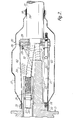
- An electric coupler (1) as shown in Figure 1, comprises a single part metal head (2) having three tubes (3) secured within it.
- the tubes (3) are of a thermoset dough-moulded polyester insulating material and are secured in the head by an epoxy adhesive.
- Each tube (3) forms an insulator for a contact (4) on the end of a respective conductor (5) of a three core wire armoured cable (6).
- the contact (4) is made of copper and is crimped on to its exposed conductor (5) and held within the corresponding tube (3) by a brass contact securing ring (7) screwed on to the contact.
- An insulating sleeve (8) formed from a heat shrinkable plastics material, surrounds each crimped joint to keep the interstices of the stranded conductor free from the insulating compound with which the coupler will in due course be filled.
- the cable armouring (9) is connected to a clamp (10) which is mounted on metal support pillars (11) which are screwed into and extend from the metal head (2).
- the clamp (10) comprises three metal rings (12) through which the cable conductors pass, the rings being fastened together by nuts (13) which are screwed on to the support pillars (11), with the armouring clamped between the rings.
- the void space (17) within the housing (14) is filled with an polyurethane casting resin which was poured through an aperture (18) in the housing after the coupler had been assembled.
- An alternative electric coupler (20), as shown in Figure 2, is substantially the same except for the features about to be described. It comprises a two part metal head (21); a front part (22) forming a face for the coupler, and a rear part (23) forming screening fins between the contacts (24).
- the insulating tubes (25) which form the contact housings are secured in position by clamping a portion (26) of each tube between the two parts of the head.
- the front part (22) and rear part (23) of the metal head (21) are secured together by the support pillars (27) which extend through apertures (28) in the rear part and are screwed into the front part.
- the support pillars (27) form the mountings for the armour clamp (29).
- the cable (30) comprises three screened conductors (31)
- the conductor screens (32) are mechanically and electrically connected to the clamp (29) by a fastening screw (33).
- a brass screening mesh (34) is positioned around the contacts and conductors to form an outer screen, the mesh being mechanically and electrically connected by clamping rings (35,36) to the head (21) and the clamp (29).
- a sealing tape (39) is wrapped around the cable before the housing is clamped down.
- the void space (40) is filled with a resin after the coupler has been assembled.
Landscapes
- Surgical Instruments (AREA)
- Amplifiers (AREA)
- Electrochromic Elements, Electrophoresis, Or Variable Reflection Or Absorption Elements (AREA)
- Insulators (AREA)
- Connector Housings Or Holding Contact Members (AREA)
- Details Of Connecting Devices For Male And Female Coupling (AREA)
- Coupling Device And Connection With Printed Circuit (AREA)
Priority Applications (1)
| Application Number | Priority Date | Filing Date | Title |
|---|---|---|---|
| AT84306423T ATE70668T1 (de) | 1983-09-20 | 1984-09-20 | Elektrischer verbinder. |
Applications Claiming Priority (2)
| Application Number | Priority Date | Filing Date | Title |
|---|---|---|---|
| GB838325115A GB8325115D0 (en) | 1983-09-20 | 1983-09-20 | Electric coupler |
| GB8325115 | 1983-09-20 |
Publications (3)
| Publication Number | Publication Date |
|---|---|
| EP0136156A2 true EP0136156A2 (de) | 1985-04-03 |
| EP0136156A3 EP0136156A3 (en) | 1987-09-23 |
| EP0136156B1 EP0136156B1 (de) | 1991-12-18 |
Family
ID=10549025
Family Applications (1)
| Application Number | Title | Priority Date | Filing Date |
|---|---|---|---|
| EP84306423A Expired - Lifetime EP0136156B1 (de) | 1983-09-20 | 1984-09-20 | Elektrischer Verbinder |
Country Status (6)
| Country | Link |
|---|---|
| EP (1) | EP0136156B1 (de) |
| AT (1) | ATE70668T1 (de) |
| CA (1) | CA1214837A (de) |
| DE (1) | DE3485362D1 (de) |
| GB (2) | GB8325115D0 (de) |
| ZA (1) | ZA847420B (de) |
Cited By (7)
| Publication number | Priority date | Publication date | Assignee | Title |
|---|---|---|---|---|
| EP0203686A1 (de) * | 1985-04-02 | 1986-12-03 | BICC Public Limited Company | Elektrische Verbindung |
| GB2254739A (en) * | 1991-03-25 | 1992-10-14 | Raychem Ltd | Cable joint |
| GB2284110A (en) * | 1991-03-25 | 1995-05-24 | Raychem Ltd | Sealing of cable crutch |
| WO1998015037A1 (en) * | 1996-09-30 | 1998-04-09 | Metal Manufactures Limited | Electrical plug |
| US6039604A (en) * | 1996-09-30 | 2000-03-21 | Metal Manufactures Limited | Cable coupling assembly |
| AU744118B2 (en) * | 1996-09-30 | 2002-02-14 | Metal Manufactures Limited | Electrical plug |
| CN102263341A (zh) * | 2010-05-25 | 2011-11-30 | 泰科电子(上海)有限公司 | 电连接器组件的密封方法以及密封结构 |
Families Citing this family (2)
| Publication number | Priority date | Publication date | Assignee | Title |
|---|---|---|---|---|
| GB8508558D0 (en) * | 1985-04-02 | 1985-05-09 | Bicc Plc | Electric coupler |
| GB8512134D0 (en) * | 1985-05-14 | 1985-06-19 | Bicc Plc | Electric coupler |
Family Cites Families (4)
| Publication number | Priority date | Publication date | Assignee | Title |
|---|---|---|---|---|
| GB856106A (en) * | 1958-03-11 | 1960-12-14 | British Insulated Callenders | Improvements in and relating to electric cable couplings |
| DE1640048A1 (de) * | 1967-09-20 | 1971-06-16 | Elektra Tailfingen | Isolierstoff-Kragensteckvorrichtung |
| GB1362270A (en) * | 1972-07-06 | 1974-08-07 | British Insulated Callenders | Two-part electric couplings |
| GB2079547B (en) * | 1980-06-25 | 1984-06-27 | Bicc Ltd | Electric connectors |
-
1983
- 1983-09-20 GB GB838325115A patent/GB8325115D0/en active Pending
-
1984
- 1984-09-20 ZA ZA847420A patent/ZA847420B/xx unknown
- 1984-09-20 DE DE8484306423T patent/DE3485362D1/de not_active Expired - Lifetime
- 1984-09-20 AT AT84306423T patent/ATE70668T1/de not_active IP Right Cessation
- 1984-09-20 GB GB08423873A patent/GB2147154B/en not_active Expired
- 1984-09-20 CA CA000463698A patent/CA1214837A/en not_active Expired
- 1984-09-20 EP EP84306423A patent/EP0136156B1/de not_active Expired - Lifetime
Cited By (9)
| Publication number | Priority date | Publication date | Assignee | Title |
|---|---|---|---|---|
| EP0203686A1 (de) * | 1985-04-02 | 1986-12-03 | BICC Public Limited Company | Elektrische Verbindung |
| GB2254739A (en) * | 1991-03-25 | 1992-10-14 | Raychem Ltd | Cable joint |
| GB2284110A (en) * | 1991-03-25 | 1995-05-24 | Raychem Ltd | Sealing of cable crutch |
| GB2284110B (en) * | 1991-03-25 | 1995-10-04 | Raychem Ltd | Cable closure arrangement |
| GB2254739B (en) * | 1991-03-25 | 1995-10-04 | Raychem Ltd | Cable joint |
| WO1998015037A1 (en) * | 1996-09-30 | 1998-04-09 | Metal Manufactures Limited | Electrical plug |
| US6039604A (en) * | 1996-09-30 | 2000-03-21 | Metal Manufactures Limited | Cable coupling assembly |
| AU744118B2 (en) * | 1996-09-30 | 2002-02-14 | Metal Manufactures Limited | Electrical plug |
| CN102263341A (zh) * | 2010-05-25 | 2011-11-30 | 泰科电子(上海)有限公司 | 电连接器组件的密封方法以及密封结构 |
Also Published As
| Publication number | Publication date |
|---|---|
| EP0136156A3 (en) | 1987-09-23 |
| GB8423873D0 (en) | 1984-10-24 |
| ATE70668T1 (de) | 1992-01-15 |
| DE3485362D1 (de) | 1992-01-30 |
| EP0136156B1 (de) | 1991-12-18 |
| GB8325115D0 (en) | 1983-10-19 |
| GB2147154A (en) | 1985-05-01 |
| ZA847420B (en) | 1985-04-24 |
| CA1214837A (en) | 1986-12-02 |
| GB2147154B (en) | 1987-04-15 |
Similar Documents
| Publication | Publication Date | Title |
|---|---|---|
| CA2962049C (en) | Cable gland assembly | |
| EP0391520A1 (de) | Abgeschirmte Verbindungen für einen elektrischen Kabelsteckverbinder | |
| US2788385A (en) | Splice closure for sheathed cable | |
| US4152538A (en) | Pressurized cable termination seal and methods of making | |
| EP0136156B1 (de) | Elektrischer Verbinder | |
| US4518819A (en) | Clamp assembly for power cables | |
| EP0203686B1 (de) | Elektrische Verbindung | |
| GB2173359A (en) | Electric coupler | |
| US3792191A (en) | Enclosure for conductor of electrical transmission system | |
| US4169966A (en) | Electrical cable joint casing | |
| US4357067A (en) | Connector for a coaxial cable | |
| US6485326B1 (en) | High-voltage connection enclosure and method | |
| EP0203751A2 (de) | Elektrischer Verbinder | |
| GB2060281A (en) | Electric cable barrier | |
| US5941717A (en) | Arrangement for introducing the end of a shielded electric line into a metal housing | |
| EP0071482A1 (de) | Verbindungszusammenbau und Verfahren für Energiekabel | |
| GB2075770A (en) | Improvements in or relating to cable glands | |
| GB2080010A (en) | High Tension Ignition Cable | |
| SU674130A1 (ru) | Муфта дл соединени коаксиальных кабелей | |
| GB2081529A (en) | Electric plug assembly | |
| SE8203157L (sv) | Oljefylld elektrisk kabelledning | |
| GB2262835A (en) | Multi-core electric power cables | |
| GB2246027A (en) | Screw-clamp earth terminals | |
| JPS5895302A (ja) | 光フアイバケ−ブルの製造方法 | |
| GB2277642A (en) | Split collar |
Legal Events
| Date | Code | Title | Description |
|---|---|---|---|
| PUAI | Public reference made under article 153(3) epc to a published international application that has entered the european phase |
Free format text: ORIGINAL CODE: 0009012 |
|
| AK | Designated contracting states |
Designated state(s): AT BE CH DE FR IT LI LU NL SE |
|
| PUAL | Search report despatched |
Free format text: ORIGINAL CODE: 0009013 |
|
| AK | Designated contracting states |
Kind code of ref document: A3 Designated state(s): AT BE CH DE FR IT LI LU NL SE |
|
| 17P | Request for examination filed |
Effective date: 19871214 |
|
| 17Q | First examination report despatched |
Effective date: 19891005 |
|
| GRAA | (expected) grant |
Free format text: ORIGINAL CODE: 0009210 |
|
| AK | Designated contracting states |
Kind code of ref document: B1 Designated state(s): AT BE CH DE FR IT LI LU NL SE |
|
| PG25 | Lapsed in a contracting state [announced via postgrant information from national office to epo] |
Ref country code: SE Effective date: 19911218 |
|
| REF | Corresponds to: |
Ref document number: 70668 Country of ref document: AT Date of ref document: 19920115 Kind code of ref document: T |
|
| ET | Fr: translation filed | ||
| REF | Corresponds to: |
Ref document number: 3485362 Country of ref document: DE Date of ref document: 19920130 |
|
| ITF | It: translation for a ep patent filed | ||
| RAP2 | Party data changed (patent owner data changed or rights of a patent transferred) |
Owner name: BICC PUBLIC LIMITED COMPANY |
|
| PLBE | No opposition filed within time limit |
Free format text: ORIGINAL CODE: 0009261 |
|
| STAA | Information on the status of an ep patent application or granted ep patent |
Free format text: STATUS: NO OPPOSITION FILED WITHIN TIME LIMIT |
|
| 26N | No opposition filed | ||
| PGFP | Annual fee paid to national office [announced via postgrant information from national office to epo] |
Ref country code: FR Payment date: 19930809 Year of fee payment: 10 |
|
| PGFP | Annual fee paid to national office [announced via postgrant information from national office to epo] |
Ref country code: AT Payment date: 19930810 Year of fee payment: 10 |
|
| PGFP | Annual fee paid to national office [announced via postgrant information from national office to epo] |
Ref country code: DE Payment date: 19930813 Year of fee payment: 10 Ref country code: CH Payment date: 19930813 Year of fee payment: 10 |
|
| PGFP | Annual fee paid to national office [announced via postgrant information from national office to epo] |
Ref country code: BE Payment date: 19930823 Year of fee payment: 10 |
|
| PGFP | Annual fee paid to national office [announced via postgrant information from national office to epo] |
Ref country code: LU Payment date: 19930903 Year of fee payment: 10 |
|
| PGFP | Annual fee paid to national office [announced via postgrant information from national office to epo] |
Ref country code: NL Payment date: 19930930 Year of fee payment: 10 |
|
| EPTA | Lu: last paid annual fee | ||
| PG25 | Lapsed in a contracting state [announced via postgrant information from national office to epo] |
Ref country code: LU Free format text: LAPSE BECAUSE OF NON-PAYMENT OF DUE FEES Effective date: 19940920 Ref country code: AT Effective date: 19940920 |
|
| PG25 | Lapsed in a contracting state [announced via postgrant information from national office to epo] |
Ref country code: LI Effective date: 19940930 Ref country code: CH Effective date: 19940930 Ref country code: BE Effective date: 19940930 |
|
| BERE | Be: lapsed |
Owner name: BICC P.L.C. Effective date: 19940930 |
|
| PG25 | Lapsed in a contracting state [announced via postgrant information from national office to epo] |
Ref country code: NL Effective date: 19950401 |
|
| NLV4 | Nl: lapsed or anulled due to non-payment of the annual fee | ||
| PG25 | Lapsed in a contracting state [announced via postgrant information from national office to epo] |
Ref country code: FR Effective date: 19950531 |
|
| REG | Reference to a national code |
Ref country code: CH Ref legal event code: PL |
|
| PG25 | Lapsed in a contracting state [announced via postgrant information from national office to epo] |
Ref country code: DE Effective date: 19950601 |
|
| REG | Reference to a national code |
Ref country code: FR Ref legal event code: ST |