EP0136220A1 - Système de pompage pour chromatographie en phase liquide - Google Patents
Système de pompage pour chromatographie en phase liquide Download PDFInfo
- Publication number
- EP0136220A1 EP0136220A1 EP84401725A EP84401725A EP0136220A1 EP 0136220 A1 EP0136220 A1 EP 0136220A1 EP 84401725 A EP84401725 A EP 84401725A EP 84401725 A EP84401725 A EP 84401725A EP 0136220 A1 EP0136220 A1 EP 0136220A1
- Authority
- EP
- European Patent Office
- Prior art keywords
- cylinder
- pumping system
- suction
- cylinders
- displacement
- Prior art date
- Legal status (The legal status is an assumption and is not a legal conclusion. Google has not performed a legal analysis and makes no representation as to the accuracy of the status listed.)
- Granted
Links
- 238000004587 chromatography analysis Methods 0.000 title claims 2
- 239000007791 liquid phase Substances 0.000 title claims 2
- 238000006073 displacement reaction Methods 0.000 claims abstract description 18
- 238000005086 pumping Methods 0.000 claims abstract description 13
- 239000007788 liquid Substances 0.000 claims abstract description 8
- 238000011144 upstream manufacturing Methods 0.000 claims description 12
- 239000012071 phase Substances 0.000 claims 3
- 238000004811 liquid chromatography Methods 0.000 abstract description 2
- XLYOFNOQVPJJNP-UHFFFAOYSA-N water Substances O XLYOFNOQVPJJNP-UHFFFAOYSA-N 0.000 description 1
Images
Classifications
-
- F—MECHANICAL ENGINEERING; LIGHTING; HEATING; WEAPONS; BLASTING
- F04—POSITIVE - DISPLACEMENT MACHINES FOR LIQUIDS; PUMPS FOR LIQUIDS OR ELASTIC FLUIDS
- F04B—POSITIVE-DISPLACEMENT MACHINES FOR LIQUIDS; PUMPS
- F04B5/00—Machines or pumps with differential-surface pistons
- F04B5/02—Machines or pumps with differential-surface pistons with double-acting pistons
-
- F—MECHANICAL ENGINEERING; LIGHTING; HEATING; WEAPONS; BLASTING
- F04—POSITIVE - DISPLACEMENT MACHINES FOR LIQUIDS; PUMPS FOR LIQUIDS OR ELASTIC FLUIDS
- F04B—POSITIVE-DISPLACEMENT MACHINES FOR LIQUIDS; PUMPS
- F04B11/00—Equalisation of pulses, e.g. by use of air vessels; Counteracting cavitation
- F04B11/005—Equalisation of pulses, e.g. by use of air vessels; Counteracting cavitation using two or more pumping pistons
- F04B11/0075—Equalisation of pulses, e.g. by use of air vessels; Counteracting cavitation using two or more pumping pistons connected in series
- F04B11/0083—Equalisation of pulses, e.g. by use of air vessels; Counteracting cavitation using two or more pumping pistons connected in series the pistons having different cross-sections
Definitions
- the object of the present invention is in improvements to pumping systems for liquids with a constant and precise flow over time, that is to say in which the instantaneous flow of liquid is precisely maintained at predetermined values.
- This type of pumping system finds many industrial applications, in particular in the field of precision instrumentation and, in particular, in liquid chromatography.
- the total flow must be 300 cm 3 in 40 seconds, or 75 cm 3 in 10 seconds.
- the upstream cylinder sucks 300 cm 3
- the downstream cylinder must discharge 75 cm 3 , which defines its capacity.
- the upstream cylinder delivers 300 cm 3
- the downstream cylinder draws 75 cm 3 , the rest.
- 225 cm 3 is driven back down at the rate of 75 cm 3 per 10 seconds. We then return to the beginning of the cycle.
- V is the volume of the upstream cylinder
- t A1 the suction time of the upstream cylinder t Ri
- t A1 + t R1 represent the period of the operating cycle
- the suction times of the upstream cylinder are followed by non-suction times since the second cylinder feeds on the discharge of the first. If so, the total flow is low, either because. small volumes, that is to say because of a long period for the cycle one does not run into too serious difficulties, but as soon as one increases the flow rates, i.e. either the volumes, or the frequencies , or both, we can witness various phenomena such as cavitation or water hammer.
- the object of the present invention is to remedy these drawbacks by ensuring constant flow both at suction and at delivery.
- devices of the type of the above assembly are preceded by at least one reserve cylinder mounted like the others in T on the supply pipe, the T being preceded on the pipe by a valve or equivalent .
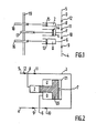
- FIGS. 1 and 2 each schematically represent in section two variants of devices according to the invention.
- FIG. 1 three cylinders 0, 1 and 2, are mounted in T on a pipe 3 taking at 4 the liquid from an upstream source not shown to discharge it at 5; the T fittings, 6, 7 and 8 are preceded, separated and followed by non-return valves or equivalent symbolized by the arrows 9, 10, 11 and 12, so that the liquid can only pass from 4 to 6, from 6 to 7, from 7 to 8 and from 8 to 5, except for the deviations towards the cylinders.
- the cylinders 0, 1 and 2 are provided with pistons 13, 14 and 15 controlled by cams 16, 17 and 18 carried by a common shaft.
- cams are identical here but mounted for 16 and 18 in the same position and for 17 in position shifted by ⁇ (180 °), their profile generates a linear movement of the pistons in one direction and in the other from where a profile of cam in arithmetic spirals, one for the going of the pistons and the other for the return.
- V 0 , V 1 and V 2 are the respective displacements of cylinders 0, 1 and 2
- t A is the suction time
- t R the delivery time with the indices 0, 1, 2 corresponding to the cylinders
- the sections of the cylinders 0, 1 and 2 are respectively proportional to t R1 , t A1 + t R1 and t A1 and their diameters to
- FIG. 2 there is shown schematically a double bore cylinder system with a single piston 20 with two diameters corresponding to the two bores and delimiting three chambers 0, 1 and 2 between piston and bottom of the double cylinder and between change planes double cylinder and piston section. These chambers 0, 1 and 2 correspond to those of FIG. 1. It can be seen that the stroke of the piston is the same for the three chambers, but opposite for 0, 2 on the one hand and 1 on the other hand. If the movement of the piston actuated by any device not shown is linear in one direction during t A 1 and in the other during t R 1 and if the sections of 0, 1 and 2 correspond to the above defined equation, we find a system equivalent to that of FIG. 1. These same indices designate equivalent elements there. Note that the section of 0 and the section of 2 necessarily have a sum equal to that of 1.
Landscapes
- Engineering & Computer Science (AREA)
- Mechanical Engineering (AREA)
- General Engineering & Computer Science (AREA)
- Reciprocating Pumps (AREA)
- Treatment Of Liquids With Adsorbents In General (AREA)
Abstract
Description
- La présente invention a pour objet dans perfectionnements aux systèmes de pompage de liquides à débit constant et précis dans le temps, c'est-à-dire dans lesquels le débit instantané de liquide est maintenu avec précision à des valeurs prédéterminées. Ce type de systèmes de pompage trouve de nombreuses applications industrielles, notamment dans le domaine de l'instrumentation de précision et, en particulier, en chromatographie en phase liquide.
- On a proposé dans l'art antérieur de monter deux cylindres munis de pistons montés en T sur la canalisation d'alimentation la canalisation étant équipée de part et d'autre des T et entre eux de clapets ou équivalents évitant un reflux du liquide vers la source. Le rôle du premier cylindre est d'alimenter en liquide pendant l'aller du piston, tandis que le second cylindre assure l'intérim de l'action du premier pendant la phase d'aspiration de ce premier cylindre. Si le cylindre amont (le premier cylindre) a une capacité de 300 cm3, une phase d'aspiration de 10 secondes et une phase de refoulement linéaire (à débit constant) de 30 secondes, le cylindre aval (le second) va prélever sur les 300 cm3 passant à hauteur de son T une quantité qui va ensuite compenser l'absence de débit du cylindre amont pendant sa période d'aspiration.
- On conçoit donc que le débit total doit être de 300 cm3 en 40 secondes, soit 75 cm3 par 10 secondes. Lorsque pendant 10 secondes, le cylindre amont aspire 300 cm3, le cylindre aval doit refouler 75 cm3, ce qui définit sa capacité. Lorsque pendant 30 secondes, le cylindre amont refoule 300cm3, le cylindre aval prélève 75 cm3, le reste.225 cm3 étant refoulé vers l'aval à raison de 75 cm3 par 10 secondes. On revient ensuite au début du cycle.
- Du côté aval, on a donc 75 cm3 provenant du cylindre aval pendant 10 secondes, puis 225 cm3 provenant du cylindre amont pendant 30 secondes. Si les pistons se déplacent linéairement, le débit est maintenu constant. Si leurs courses sont égales, les sections droites des cylindres sont proportionnelles aux capacités, 300 cm3 pour le cylindre amont et 75 cm3 pour le cylindre aval. Les pistons se déplacent alors à l'inverse, l'un refoulant pendant le temps d'aspiration de l'autre et réciproquement. Ceci peut être obtenu par montage en opposition, par arbre à cames ou tout autre moyen adéquat.
- Plus généralement, si V, est le volume du cylindre amont, Vz celui du cylindre aval, tA1 le temps d'aspiration du cylindre amont tRi, sont temps de refoulement, on déduit de ce principe que:

- En fait, du côté amont, les temps d'aspiration du cylindre amont sont suivis de temps de non-aspiration puisque le second cylindre s'alimente sur le refoulement du premier. Si donc, le débit total est faible, soit du fait. de petits volumes, soit du fait d'une période longue pour le cycle on ne se heurte pas à de trop graves difficultés, mais dès que l'on augmente les débits, c'est-à-dire soit les volumes, soit les fréquences,soit les deux, on peut assister à divers phénomènes tels que la cavitation ou les coups de bélier.
- La présente invention a pour but de porter remède à ces inconvénients en assurant une constance du débit tant à l'aspiration qu'au refoulement.
- Pour cela, on fait précéder des dispositifs du type de l'ensemble ci-dessus par au moins un cylindre de réserve monté comme les autres en T sur la canalisation d'alimentation, le T étant précédé sur la canalisation d'un clapet ou équivalent.
- Pour mieux faire comprendre les caractéristiques techniques et les avantages de la présente invention, on va en décrire deux exemples de réalisation étant bien entendu que ceux-ci ne sont pas limitatifs quant à leur mode de mise en oeuvre et aux applications qu'on peut en faire.
- On se reportera aux figures 1 et 2 qui représentent chacune schématiquement en coupe deux variantes de dispositifs conformes à l'invention.
- A la figure 1, trois cylindres 0, 1 et 2, sont montés en T sur une canalisation 3 prélevant en 4 du liquide dans une source amont non représentée pour le refouler en 5; les raccords en T, 6, 7 et 8 sont précédés, séparés et suivis par des clapets de non retour ou équivalents symbolisés par les flèches 9, 10, 11 et 12, de sorte que le liquide ne peut passer que de 4 en 6, de 6 en 7, de 7 en 8 et de 8 en 5, aux déviations vers les cylindres près.
- Les cylindres 0, 1 et 2 sont munis de pistons 13, 14 et 15 commandés par des cames 16, 17 et 18 portées par un arbre commun. Un système de rappel ou autre adéquat non représenté fait suivre, aux pistons, les mouvements des cames correspondantes aussi bien dans un sens de déplacement que dans l'autre.
- Ces cames sont ici identiques mais montées pour 16 et 18 dans la même position et pour 17 en position décalée de Π (180°), leur profil engendre un mouvement linéaire des pistons dans un sens et dans l'autre d'où un profil de came en spirales arithmétiques, l'une pour l'aller des pistons et l'autre pour le retour.
- Si V0, V1 et V2 sont les cylindrées respectives des cylindres 0, 1 et 2, si tA est le temps d'aspiration, tR le temps de refoulement avec les indices 0, 1, 2 correspondant aux cylindres, on a:


- Dans ces conditions, le débit en 4 et le débit en 5 sont constants. On déduit de l'égalité précédente que V0 + V2 = V1
- Si les courses des pistons 13, 14, 15 sont égales, les sections des cylindres 0, 1 et 2 sont respectivement proportionnelles à tR1, tA1 + tR1 et tA1 et leurs diamètres à

- On peut imaginer de remplacer chaque cylindre par un ou plusieurs, par exemple identiques, le nombre sera alors proportionnel aux temps tR1, tA
1 + t R1 et tA1 . - A la figure 2, on a représenté schématiquement un système à cylindre à double alésage et à piston unique 20 à deux diamètres correspondant aux deux alésages et délimitant trois chambres 0, 1 et 2 entre piston et fonds du double cylindre et entre plans de changement de section du double cylindre et du piston. Ces chambres 0, 1 et 2 correspondent à celles de la figure 1. On constate que la course du piston est la même pour les trois chambres, mais opposée pour 0, 2 d'une part et 1 d'autre part. Si le mouvement du piston actionné par tout dispositif non représenté est linéaire dans un sens pendant tA
1 et dans l'autre pendant tR1 et si les sections de 0, 1 et 2 répondent à l'équation ci-dessus définie, on retrouve un système équivalent à celui de la figure 1. Ces mêmes indices y désignent des éléments équivalents. On remarquera que nécessairement la section de 0 et la section de 2 ont une somme égale à celle de 1. - On remarquera qu'aux figures 1 et 2, les dispositifs anti-retour portent les mêmes repères et que, en pratique, les dispositifs 9 et 12 ne sont pas indispensables.
- On remarquera également que le double cylindre de la figure 2 peut être monté différemment, la cylindrée de gauche pouvant devenir la première (0), la cylindrée médiane la troisième (2) et la cylindrée de droite (1) restant la seconde. Il suffit, pour cela, d'inverser les dispositifs anti- retour 9, 10, 11 et 12.
- On peut également imaginer sans sortir du cadre de la présente invention des dispositifs dans lesquels on peut faire varier cylindrées et temps d'aspiration et de refoulement.
- Ceci peut se faire, par exemple, en modifiant la course des pistons, notamment en changeant ou en modifiant les cames.
- Ceci peut également se faire par exemple par des séries de cylindres montés en T sur une ou plusieurs canalisations parallèles, les T étant séparés par des clapets anti retour. On peut alors considérer des séries de cylindres successifs, par exemple identiques dont la cylindrée totale de chaque série correspond aux cylindrées 0,1 et 2 des exemples des figures 1 et 2 : par exemple un ensemble de douze cylindres peut être divisé en 3 + 6+3 ou en 4+6+2 ou en 5+6+1 les proportions des temps étant


Claims (10)
Applications Claiming Priority (2)
| Application Number | Priority Date | Filing Date | Title |
|---|---|---|---|
| FR8313995 | 1983-08-31 | ||
| FR8313995A FR2551505B1 (fr) | 1983-08-31 | 1983-08-31 | Systeme de pompage pour chromatographie en phase liquide |
Publications (2)
| Publication Number | Publication Date |
|---|---|
| EP0136220A1 true EP0136220A1 (fr) | 1985-04-03 |
| EP0136220B1 EP0136220B1 (fr) | 1988-01-20 |
Family
ID=9291925
Family Applications (1)
| Application Number | Title | Priority Date | Filing Date |
|---|---|---|---|
| EP84401725A Expired EP0136220B1 (fr) | 1983-08-31 | 1984-08-28 | Système de pompage pour chromatographie en phase liquide |
Country Status (7)
| Country | Link |
|---|---|
| US (1) | US4643651A (fr) |
| EP (1) | EP0136220B1 (fr) |
| JP (1) | JPS6073068A (fr) |
| BE (1) | BE900437A (fr) |
| DE (1) | DE3468917D1 (fr) |
| FR (1) | FR2551505B1 (fr) |
| IT (1) | IT1180812B (fr) |
Cited By (1)
| Publication number | Priority date | Publication date | Assignee | Title |
|---|---|---|---|---|
| EP0340374A1 (fr) * | 1988-05-02 | 1989-11-08 | Herbert Dr. Knauer | Installation de pompage pour des gradients de basse pression |
Families Citing this family (18)
| Publication number | Priority date | Publication date | Assignee | Title |
|---|---|---|---|---|
| JPH0754114B2 (ja) * | 1985-02-01 | 1995-06-07 | 日本電子株式会社 | 送液ポンプの制御方法 |
| SE8504362D0 (sv) * | 1985-09-20 | 1985-09-20 | Astra Tech Ab | Pump med kontinuerligt inflode och pulsativt utflode |
| DE3837325A1 (de) * | 1988-11-03 | 1990-05-10 | Bruker Franzen Analytik Gmbh | Fluessigkeits-kolbenpumpe fuer chromatographische analysegeraete |
| DE4211015A1 (de) * | 1992-04-02 | 1993-10-07 | Webasto Thermosysteme Gmbh | Zyklisch arbeitende Fluid-Fördervorrichtung |
| US5988165A (en) | 1997-10-01 | 1999-11-23 | Invacare Corporation | Apparatus and method for forming oxygen-enriched gas and compression thereof for high-pressure mobile storage utilization |
| FR2802577B1 (fr) | 1999-12-17 | 2002-03-08 | Peugeot Citroen Automobiles Sa | Pompe a pistons multiples et a comportement vibratoire ameliore |
| FI110960B (fi) * | 2000-04-27 | 2003-04-30 | Matti Vilenius | Kytkentä ja menetelmä hydraulikoneen tilavuusvirran vaihtelujen tasoittamiseksi |
| DE102004061813A1 (de) * | 2004-12-22 | 2006-07-06 | Robert Bosch Gmbh | Kolbenpumpe mit wenigstens einem Kolbenelement |
| US8062003B2 (en) * | 2005-09-21 | 2011-11-22 | Invacare Corporation | System and method for providing oxygen |
| JP4148425B1 (ja) * | 2007-03-12 | 2008-09-10 | 光治 馬上 | 高圧発生装置 |
| DE102009017918A1 (de) | 2009-04-17 | 2010-12-16 | Fachhochschule Jena | Verfahren und Vorrichtung zur pulsationsfreien volumetrischen Förderung von Fluiden und Suspensionen |
| DE102009027312A1 (de) * | 2009-06-30 | 2011-01-05 | Robert Bosch Gmbh | Mehrkolbenpumpe |
| EP2467578A1 (fr) * | 2009-08-17 | 2012-06-27 | Invacare Corporation | Compresseur |
| CN104220748B (zh) | 2012-02-03 | 2017-06-06 | 英瓦卡尔公司 | 泵送装置 |
| EP2667111B1 (fr) * | 2012-05-23 | 2017-07-12 | Amgat Citrus Products, S. A. | Appareil et procédé pour chauffage ohmique d'un liquide particulaire |
| JP5524285B2 (ja) * | 2012-07-10 | 2014-06-18 | 株式会社東芝 | ポンプユニット |
| JP2014066197A (ja) * | 2012-09-26 | 2014-04-17 | Hitachi Koki Co Ltd | 洗浄機 |
| AU2018204487B1 (en) * | 2017-11-10 | 2019-05-30 | Quantum Servo Pumping Technologies Pty Ltd | Pumping systems |
Citations (5)
| Publication number | Priority date | Publication date | Assignee | Title |
|---|---|---|---|---|
| GB817872A (en) * | 1956-06-09 | 1959-08-06 | Atomic Energy Authority Uk | Improvements in or relating to pumps |
| FR2294343A1 (fr) * | 1974-12-13 | 1976-07-09 | Sigma Hranice Np | Pompe a piston sans pulsations |
| FR2383330A1 (fr) * | 1977-03-08 | 1978-10-06 | Smirnov Igor | Pompe a pistons |
| DE2725464A1 (de) * | 1977-06-04 | 1978-12-14 | Mueszeripari Muevek Lab | Pulsationsfreie zumesspumpe |
| DE3203722A1 (de) * | 1982-02-04 | 1983-08-18 | Gynkotek Gesellschaft für den Bau wissenschaftlich-technischer Geräte mbH, 8000 München | Schubkolbenpumpe zur pulsationsarmen foerderung einer fluessigkeit |
Family Cites Families (10)
| Publication number | Priority date | Publication date | Assignee | Title |
|---|---|---|---|---|
| US7302A (en) * | 1850-04-23 | Subivlebged bogkee e ob | ||
| US370376A (en) * | 1887-09-27 | chichester | ||
| CH106875A (de) * | 1923-12-20 | 1925-01-16 | Escher Wyss Maschf Ag | Mehrzylindriger zweistufiger Kolben-Kompressor für Kältemaschinen. |
| US1889640A (en) * | 1931-05-25 | 1932-11-29 | Jan P Clary | Compressor apparatus |
| GB451110A (en) * | 1934-03-17 | 1936-07-27 | Kali Forschungsanstalt Gmbh | An improved process for the transport of solid or solid and liquid substances mixed with vapours and/or gases |
| DE1102787B (de) * | 1959-12-11 | 1961-03-23 | Linde Eismasch Ag | Verfahren und Einrichtung zur Verhuetung von Braenden in mehrstufigen Sauerstoffverdichtern |
| AT294586B (de) * | 1968-01-30 | 1971-11-25 | Ceskoslovenska Akademie Ved | Kolbenpumpe mit einem Hauptpumpzylinder und einem Kompensationszylinder |
| GB1258333A (fr) * | 1968-04-08 | 1971-12-30 | ||
| US3809507A (en) * | 1972-03-01 | 1974-05-07 | B Baglai | Nonpulsating fluid-flow pump |
| GB1534650A (en) * | 1977-06-14 | 1978-12-06 | Mueszeripari Muevek Lab | Pulsation-free feeding pump |
-
1983
- 1983-08-31 FR FR8313995A patent/FR2551505B1/fr not_active Expired
-
1984
- 1984-08-27 BE BE6/48002A patent/BE900437A/fr not_active IP Right Cessation
- 1984-08-28 EP EP84401725A patent/EP0136220B1/fr not_active Expired
- 1984-08-28 DE DE8484401725T patent/DE3468917D1/de not_active Expired
- 1984-08-29 JP JP59180263A patent/JPS6073068A/ja active Pending
- 1984-08-30 IT IT12591/84A patent/IT1180812B/it active
-
1985
- 1985-09-03 US US06/771,843 patent/US4643651A/en not_active Expired - Fee Related
Patent Citations (5)
| Publication number | Priority date | Publication date | Assignee | Title |
|---|---|---|---|---|
| GB817872A (en) * | 1956-06-09 | 1959-08-06 | Atomic Energy Authority Uk | Improvements in or relating to pumps |
| FR2294343A1 (fr) * | 1974-12-13 | 1976-07-09 | Sigma Hranice Np | Pompe a piston sans pulsations |
| FR2383330A1 (fr) * | 1977-03-08 | 1978-10-06 | Smirnov Igor | Pompe a pistons |
| DE2725464A1 (de) * | 1977-06-04 | 1978-12-14 | Mueszeripari Muevek Lab | Pulsationsfreie zumesspumpe |
| DE3203722A1 (de) * | 1982-02-04 | 1983-08-18 | Gynkotek Gesellschaft für den Bau wissenschaftlich-technischer Geräte mbH, 8000 München | Schubkolbenpumpe zur pulsationsarmen foerderung einer fluessigkeit |
Cited By (1)
| Publication number | Priority date | Publication date | Assignee | Title |
|---|---|---|---|---|
| EP0340374A1 (fr) * | 1988-05-02 | 1989-11-08 | Herbert Dr. Knauer | Installation de pompage pour des gradients de basse pression |
Also Published As
| Publication number | Publication date |
|---|---|
| IT1180812B (it) | 1987-09-23 |
| IT8412591A0 (it) | 1984-08-30 |
| EP0136220B1 (fr) | 1988-01-20 |
| DE3468917D1 (en) | 1988-02-25 |
| BE900437A (fr) | 1985-02-27 |
| FR2551505A1 (fr) | 1985-03-08 |
| JPS6073068A (ja) | 1985-04-25 |
| FR2551505B1 (fr) | 1988-02-26 |
| US4643651A (en) | 1987-02-17 |
Similar Documents
| Publication | Publication Date | Title |
|---|---|---|
| EP0136220A1 (fr) | Système de pompage pour chromatographie en phase liquide | |
| EP1876353B1 (fr) | Pompe transfert à plusieurs pistons | |
| FR2641509A1 (fr) | Dispositif pour une unite de commande hydraulique prevue notamment dans des systemes antiblocage de freins de vehicules | |
| FR2492008A1 (fr) | Pompe doseuse | |
| FR2783021A1 (fr) | Procede et systeme de pompage de fluide utilisant une pompe avec un debit constant a l'aspiration ou au refoulement | |
| FR2713583A1 (fr) | Dispositif de tension de chenille. | |
| FR2507144A1 (fr) | Direction assistee, notamment pour vehicules utilitaires | |
| FR2366473A1 (fr) | Systeme hydraulique pour milieux extremement froids | |
| FR2624215A1 (fr) | Pignons flottants pour machine a vis haute pression | |
| EP0840010A3 (fr) | Pompe à piston | |
| EP0072732B1 (fr) | Régulateur de débit pour installation de direction assistée | |
| FR2621354A1 (fr) | Dispositif de commande independant de la charge pour appareils utilisateurs hydrauliques | |
| FR2532694A1 (fr) | Entrainement hydrostatique comprenant, notamment, une pompe a palettes reglable | |
| FR2595416A1 (fr) | Pompe a pistons radiaux | |
| FR2492902A1 (fr) | Pompe volumetrique a perfusion a doigts et le dispositif d'entrainement de ces doigts | |
| FR2475643A1 (fr) | Tete de pompe mono-piston a volume interne constant, en particulier pour alimenter en solvant les colonnes chromatographiques | |
| FR2580833A1 (fr) | Dispositifs de regulation pour pompes doseuses a plusieurs corps et application de ces dispositifs a la chromatographie | |
| EP0604332A1 (fr) | Procédé et dispositif pour la mise en mouvement ou l'arrêt d'un moteur hydraulique entraînant un ensemble présentant une grande inertie | |
| FR2873765A1 (fr) | Pompe a piston de construction compacte | |
| FR2994230A1 (fr) | Pompe a engrenage a denture interieure dont l'intervalle du separateur comporte un passage | |
| EP1240429B1 (fr) | Pompe a pistons multiples et a comportement vibratoire ameliore | |
| FR2473973A1 (fr) | Regulateur de pression jumele pour installation de freinage hydraulique | |
| FR3091561A1 (fr) | Microcentrale hydraulique | |
| FR2645271A1 (fr) | Dispositif de reglage d'echantillonneur de prod uit liquide | |
| FR2566053A1 (fr) | Pompe hydraulique manuelle a debit et couple d'entree variables, assujetties a l'effort de l'utilisateur |
Legal Events
| Date | Code | Title | Description |
|---|---|---|---|
| PUAI | Public reference made under article 153(3) epc to a published international application that has entered the european phase |
Free format text: ORIGINAL CODE: 0009012 |
|
| AK | Designated contracting states |
Designated state(s): DE GB NL |
|
| TCNL | Nl: translation of patent claims filed | ||
| 17P | Request for examination filed |
Effective date: 19850720 |
|
| 17Q | First examination report despatched |
Effective date: 19860507 |
|
| GRAA | (expected) grant |
Free format text: ORIGINAL CODE: 0009210 |
|
| AK | Designated contracting states |
Kind code of ref document: B1 Designated state(s): DE GB NL |
|
| REF | Corresponds to: |
Ref document number: 3468917 Country of ref document: DE Date of ref document: 19880225 |
|
| GBT | Gb: translation of ep patent filed (gb section 77(6)(a)/1977) | ||
| PLBE | No opposition filed within time limit |
Free format text: ORIGINAL CODE: 0009261 |
|
| STAA | Information on the status of an ep patent application or granted ep patent |
Free format text: STATUS: NO OPPOSITION FILED WITHIN TIME LIMIT |
|
| 26N | No opposition filed | ||
| PGFP | Annual fee paid to national office [announced via postgrant information from national office to epo] |
Ref country code: GB Payment date: 19910802 Year of fee payment: 8 |
|
| PGFP | Annual fee paid to national office [announced via postgrant information from national office to epo] |
Ref country code: DE Payment date: 19910803 Year of fee payment: 8 |
|
| PGFP | Annual fee paid to national office [announced via postgrant information from national office to epo] |
Ref country code: NL Payment date: 19910831 Year of fee payment: 8 |
|
| PG25 | Lapsed in a contracting state [announced via postgrant information from national office to epo] |
Ref country code: GB Effective date: 19920828 |
|
| PG25 | Lapsed in a contracting state [announced via postgrant information from national office to epo] |
Ref country code: NL Effective date: 19930301 |
|
| NLV4 | Nl: lapsed or anulled due to non-payment of the annual fee | ||
| GBPC | Gb: european patent ceased through non-payment of renewal fee |
Effective date: 19920828 |
|
| PG25 | Lapsed in a contracting state [announced via postgrant information from national office to epo] |
Ref country code: DE Effective date: 19930501 |