EP0136276A1 - Procédé et appareil pour la fabrication d'une électrode à souder remplie de poudre - Google Patents
Procédé et appareil pour la fabrication d'une électrode à souder remplie de poudre Download PDFInfo
- Publication number
- EP0136276A1 EP0136276A1 EP84850249A EP84850249A EP0136276A1 EP 0136276 A1 EP0136276 A1 EP 0136276A1 EP 84850249 A EP84850249 A EP 84850249A EP 84850249 A EP84850249 A EP 84850249A EP 0136276 A1 EP0136276 A1 EP 0136276A1
- Authority
- EP
- European Patent Office
- Prior art keywords
- powder
- welding point
- metal strand
- welding
- tube
- Prior art date
- Legal status (The legal status is an assumption and is not a legal conclusion. Google has not performed a legal analysis and makes no representation as to the accuracy of the status listed.)
- Granted
Links
- 239000000843 powder Substances 0.000 title claims abstract description 122
- 238000003466 welding Methods 0.000 title claims abstract description 117
- 238000000034 method Methods 0.000 title claims description 16
- 230000008569 process Effects 0.000 title claims description 9
- 238000004519 manufacturing process Methods 0.000 title description 11
- 238000010924 continuous production Methods 0.000 claims abstract description 3
- 239000002184 metal Substances 0.000 claims description 55
- 229910052751 metal Inorganic materials 0.000 claims description 55
- 230000002411 adverse Effects 0.000 claims description 5
- 238000005192 partition Methods 0.000 claims description 4
- 230000001681 protective effect Effects 0.000 claims description 4
- 230000009467 reduction Effects 0.000 claims description 3
- 230000001133 acceleration Effects 0.000 claims description 2
- 239000002245 particle Substances 0.000 claims description 2
- 238000007493 shaping process Methods 0.000 claims description 2
- RYGMFSIKBFXOCR-UHFFFAOYSA-N Copper Chemical compound [Cu] RYGMFSIKBFXOCR-UHFFFAOYSA-N 0.000 description 4
- 229910052802 copper Inorganic materials 0.000 description 4
- 239000010949 copper Substances 0.000 description 4
- 230000008901 benefit Effects 0.000 description 3
- 239000000463 material Substances 0.000 description 3
- 238000007747 plating Methods 0.000 description 3
- 238000004140 cleaning Methods 0.000 description 2
- 238000009826 distribution Methods 0.000 description 2
- 238000010438 heat treatment Methods 0.000 description 2
- 238000005096 rolling process Methods 0.000 description 2
- 244000089486 Phragmites australis subsp australis Species 0.000 description 1
- 238000010521 absorption reaction Methods 0.000 description 1
- 238000009825 accumulation Methods 0.000 description 1
- 238000000137 annealing Methods 0.000 description 1
- 230000008859 change Effects 0.000 description 1
- 239000011248 coating agent Substances 0.000 description 1
- 238000000576 coating method Methods 0.000 description 1
- 238000011109 contamination Methods 0.000 description 1
- 230000005294 ferromagnetic effect Effects 0.000 description 1
- 239000012535 impurity Substances 0.000 description 1
- 238000005304 joining Methods 0.000 description 1
- 230000005291 magnetic effect Effects 0.000 description 1
- 239000000203 mixture Substances 0.000 description 1
- 230000035699 permeability Effects 0.000 description 1
- 238000003825 pressing Methods 0.000 description 1
- 230000001105 regulatory effect Effects 0.000 description 1
- 238000009751 slip forming Methods 0.000 description 1
- 230000007704 transition Effects 0.000 description 1
Images
Classifications
-
- B—PERFORMING OPERATIONS; TRANSPORTING
- B23—MACHINE TOOLS; METAL-WORKING NOT OTHERWISE PROVIDED FOR
- B23K—SOLDERING OR UNSOLDERING; WELDING; CLADDING OR PLATING BY SOLDERING OR WELDING; CUTTING BY APPLYING HEAT LOCALLY, e.g. FLAME CUTTING; WORKING BY LASER BEAM
- B23K35/00—Rods, electrodes, materials, or media, for use in soldering, welding, or cutting
- B23K35/40—Making wire or rods for soldering or welding
- B23K35/406—Filled tubular wire or rods
-
- B—PERFORMING OPERATIONS; TRANSPORTING
- B23—MACHINE TOOLS; METAL-WORKING NOT OTHERWISE PROVIDED FOR
- B23K—SOLDERING OR UNSOLDERING; WELDING; CLADDING OR PLATING BY SOLDERING OR WELDING; CUTTING BY APPLYING HEAT LOCALLY, e.g. FLAME CUTTING; WORKING BY LASER BEAM
- B23K35/00—Rods, electrodes, materials, or media, for use in soldering, welding, or cutting
- B23K35/40—Making wire or rods for soldering or welding
- B23K35/406—Filled tubular wire or rods
- B23K2035/408—Filled tubular wire or rods with welded longitudinal seam
-
- Y—GENERAL TAGGING OF NEW TECHNOLOGICAL DEVELOPMENTS; GENERAL TAGGING OF CROSS-SECTIONAL TECHNOLOGIES SPANNING OVER SEVERAL SECTIONS OF THE IPC; TECHNICAL SUBJECTS COVERED BY FORMER USPC CROSS-REFERENCE ART COLLECTIONS [XRACs] AND DIGESTS
- Y10—TECHNICAL SUBJECTS COVERED BY FORMER USPC
- Y10T—TECHNICAL SUBJECTS COVERED BY FORMER US CLASSIFICATION
- Y10T29/00—Metal working
- Y10T29/49—Method of mechanical manufacture
- Y10T29/49002—Electrical device making
- Y10T29/49117—Conductor or circuit manufacturing
Definitions
- the invention relates to a process for the continuous production of a powder-filled, tubular welding electrode, in which a metal strand is deformed into a channel during its advancement at a certain speed and then by joining the two edges of the channel into a tube, and the edges are continuously formed a welding point are welded together, the powder being introduced into the welded tube at a distance past the welding point, and then the cross section of the powder-filled tube is reduced to a desired dimension. Before the metal strand is formed, it has the shape of a band or wire, for example.
- this metal strand is first formed into a gutter, which is then continuously closed to form a tube, the longitudinal edges of the gutter forming a joint which is essentially parallel to the tube axis and is welded together continuously, so that the metal strand finally has the shape of a welded one Rohres has.
- a powder-filled welding electrode of this type with a welded tube, ie a seamless shell, has some essential advantages over a powder-filled welding electrode, the shell of which consists of a tube-shaped band with a fold or a closed but non-welded joint.
- the powder in the seamless welding electrode is completely shielded from the surrounding atmosphere and therefore also completely protected against unwanted moisture absorption from the air.
- it is possible to pass the seamless welding electrode during manufacture for example through a cleaning bath, in order to remove impurities, for example drawing oil residues, from its surface.
- Another advantage is that the seamless electrode is made by copper plating bad can be performed. The surface copper plating of the electrode significantly improves the current transfer properties between the electrode and a welding current supplying electrode contact.
- a band formed into a gutter is filled with powder before the edges of the gutter are welded together.
- an additional band is inserted into the welded tube synchronously with the feed speed of the channel, which serves as a welding base when the edges of the channel are welded together to form a tube.
- the welding pad is intended to protect the powder in the channel from inadmissible heating by the heat of welding.
- This manufacturing process is also complicated and, after reducing the cross section of the powder-filled and welded tube, leads to a non-uniform cross section of the casing along the periphery of the casing, which adversely affects the welding properties of this electrode.
- the channel is only filled with so much powder that the powder only takes up part of the cross-sectional area when the tube passes the welding station.
- the powder will be adversely affected by the heat of welding due to the slow transport past the welding point in time with the welding speed.
- the accumulation of the powder at the passage of the welding point cannot be checked, which would be particularly desirable if the powder is ferromagnetic and is influenced by the magnetic field generated by the welding current. This field can cause an uneven distribution of the powder in the tube, which is greatly promoted by the slow transport past the welding point. An uneven distribution of the powder in the welding electrode again adversely affects the properties of the electrode.
- the present invention has set itself the task of simplifying the manufacture of welding electrodes of the type mentioned and improving the quality of the electrodes.
- the solution to this problem according to the invention is that the metal strand is pushed downwards at least immediately in front of and behind the welding point at an angle to the horizontal plane which is greater than the angle of repose of the powder, and that the powder falls into the welded tube from such a height that it passes the welding point at a speed that is greater than the feed speed of the metal strand at the welding point.
- the angle of repose which is a measure of the internal friction of the powder, is understood to mean the angle which the lateral surface of the pouring cone forms with the horizontal plane when the powder is poured from above onto a base from a point.
- the angle of repose is a specific angle for each powder.
- the angle of repose of welding powder is roughly approx. 45 ° on average. However, there may be significant deviations from this mean. It depends, among other things, on the composition of the powder, the grain size and grain shape of the powder.
- the powder it is advantageous for the powder to pass the welding point at a speed that is at least 1.5 times as large is like the feed rate of the metal strand at the welding point.
- the greater the speed of the powder as it passes the welding point the smaller the flow cross-section used by the powder flow in the area of the welding point for a certain amount of powder per unit of time, and the shorter the time that the powder particles need to pass through the hot welding point.
- the speed of the powder after the passage of the welding point and before the reduction of the cross section by changing the feed direction of the metal strand in a direction that includes an angle with the horizontal plane that is less than the angle of repose of the powder, decelerated to the feed rate of the metal strand It is advantageous that the powder is introduced into the welded tube in such an amount per unit of time that it accumulates below the welding point after braking to the feed rate of the metal strand and the interior of the tube in time with the feed rate of the metal strand. This ensures that the powder is evenly distributed in the tube before it is compressed in the tube by the subsequent reduction in cross-section.
- the invention also relates to a device for carrying out the method, which comprises a metal strand supply, a device for feeding the metal strand, a forming arrangement for shaping the metal strand into a channel and then by bringing the edges together in a tube, a welding device for the Continuous welding of the two edges of the channel forming a weld joint, a powder magazine, a powder line with a mouthpiece which works together with the metal strand for feeding the powder from the powder magazine to the metal strand, a device for metering the supplied lines which is installed in the powder line The amount of powder per unit of time and a device attached to the welding station for reducing the cross-section of the welded, powder-filled tube is provided.
- the invention consists in that a guiding device for the downward guidance of the metal strand is provided immediately before and after it has passed through the welding station in a direction which includes an angle with the horizontal plane which is greater than the angle of repose of the powder, a drop distance for the Powder, which is formed at least partially from the powder line and the metal strand formed above the stationary welding point with respect to the device and below the welding point to the welded pipe, and this drop distance extends between an upper level above the mouthpiece and a lower level below the welding point , wherein the length of the fall distance between the upper level and the welding point for the acceleration of the falling powder is dimensioned at a speed at the passage of the welding point that is greater than the feed speed of the metal strand at the welding point is, and a second guide device is provided, which leads the powder at a distance past the welding point.
- the band of the coil 2 is usually obtained by slitting a wide metal band. This type of production often has the consequence that the cross section of the band does not remain uniform over the length of the band. The flat sides often show a somewhat convex shape. In order to ensure good welding quality, it is necessary that the ratio of the casing weight to the powder weight remains constant over the entire length of the electrode. With the calibration device, the required constant cross-section is achieved over the entire length of the belt.
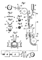
- the band 1 advanced here from the spool 2 through the calibration device 3 is guided over an upper deflection roller 5, from which the band is guided downwards steeply to a lower deflection roller 19.
- the belt forms an angle with the horizontal plane that is only slightly less than 90 °.
- the band is first successively formed into a groove 1a by the forming rollers 4a, 4b and 4c. More forming rollers 4d and 4e form the groove 1a closing l I in a pipe 1b.
- the number of forming rolls which are only shown schematically here, can vary.
- the change in the cross-sectional shape in the course of the forming is shown in FIGS. 2 to 5. These cross sections are shown on a larger scale.
- the cross-section transition forms from tape to Closed pipes can have very different appearances depending on the manufacturing process used.
- the edges 6, 7 of the channel form a joint 8.
- the tube is shown with a circular cross section (FIG. 5).
- FIG. 5 As mentioned above, other cross-sectional shapes are also conceivable, in particular elliptical shapes, the long axis of the ellipse being laid through the joint.
- the tube 1b is continuously welded along the joint in a welding station 9, which is only indicated here, and receives the cross section shown in FIG.
- continuous welding processes with or without additional material can be used to weld the pipe.
- the continuous welding processes also include, for example, welding processes in which the energy supply to the welding point is pulsating, such as pulse welding, AC welding and similar processes.
- a welding device suitable for this purpose is shown schematically in FIG. It is a resistance seam welding machine with two roller electrodes 10 and two support rollers 11 for pressing the edges 6, 7 together at the welding point 12.
- the welding point remains stationary within the welding station 9, while the metal strand 1 passes through at a predetermined speed, namely the welding speed the welding station is advanced.
- the powder 17 is fed from a powder container 13 with a metering device 14 with a connected powder quantity regulator 14a through a powder line 15 to the not completely closed channel 1a.
- the powder falling through the powder line 15 is guided by a mouthpiece 16 at the front end of the powder line 15 to the bottom of the channel 1a and slides and falls along the steeply inclined channel 1a past the welding point in the welding station 9 down into the welded tube 1b .
- the speed of the falling powder increases continuously.
- the length of the falling distance for the powder between an upper level - here the metering device 14 - and the stationary welding point in the welding station 9 is chosen so large that the speed of the powder as it passes through the welding point is at least about 1.5 times, preferably about 2 times is like the speed of the metal strand in the welding station.
- the fall of the powder is braked below the welding point by the deflection of the strand of material in a horizontal direction or possibly in a direction that includes an angle with the horizontal plane that is smaller than the angle of repose of the powder.
- the powder collects at a level 18 which is at a distance below the welding point such that the heat of welding can no longer adversely affect the powder.
- the position of the level 18 is achieved by a corresponding metering of the quantity of powder per unit of time by the quantity regulator 14a.
- the powder filling factor of the pipe is measured in the area of level 18 with a display device.
- the display device 24 is equipped with a coil 25 surrounding the tube 1b with which the common permeability of the tube and the powder filling is measured. If the powder filling factor at level 18 does not correspond to a predetermined value, the display device 24 emits an error signal via a signal line 26 to the powder quantity controller 14a, with which the powder quantity setting is changed until the correct filling factor is reached again. At the same time, the deviation of the powder filling from the specified value is also indicated by a warning lamp 27.
- the powder-filled pipe 1b is fed from the lower deflection roller 19 to a rolling device 20, where the cross section is reduced to a certain extent.
- the cross section is then reduced to the desired electrode diameter by a drawing process in a drawing system 21.
- the drawing process is expediently carried out with intermediate annealing of the electrode in several stages.
- the finished electrode passes through a loop stock 22 to compensate for length variations before it is wound up on a spool 23.
- the metal strand 1 is fed by means of the “forming rollers 4a-4e, the deflection rollers 5, 19 and the rolling device 20 and drawing system 21, which are all provided with corresponding feed devices (not shown here). These devices are operationally matched to one another such that the speed of the metal strand is always adapted to the dimension, so the speed of the metal strand through the drawing system is of course much greater than the speed of the metal strand at the welding point.
- a protective gas container is connected by means of a line 29a to a valve 29, from which a gas line 30 with a gas mouthpiece 31 leads into the interior of the not yet closed channel.
- the gas supply is regulated in such a way that the section of the pipe between the gas mouthpiece 31 and the level 18 is kept under a slight excess pressure, so that this section is essentially filled with protective gas, for example C0 2 .
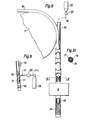
- the metal strand is guided downward essentially vertically from the upper deflection roller 5.
- the powder is introduced from a powder container 32 with a quantity regulator 33 and a powder line 34, which is only indicated here, through a filling tube 35 into the welded tube below the welding point.
- the filling tube 35 represents the front end of the powder line 34 and is inserted into the welded tube from above.
- the powder falling through the filling tube 35 at a greater speed than that of the metal strand is thus guided past the welding point at a distance, since the filling tube forms a partition between the welding point and powder, and, moreover, is only exposed to the welding heat for a very short time. Otherwise, the device is the same as that described in connection with FIG. 1.
Landscapes
- Engineering & Computer Science (AREA)
- Mechanical Engineering (AREA)
- Arc Welding In General (AREA)
- Butt Welding And Welding Of Specific Article (AREA)
- Powder Metallurgy (AREA)
Applications Claiming Priority (2)
| Application Number | Priority Date | Filing Date | Title |
|---|---|---|---|
| SE8304658 | 1983-08-29 | ||
| SE8304658A SE8304658L (sv) | 1983-08-29 | 1983-08-29 | Forfarande och anordning for kontinuerlig tillverkning av pulverfylld svetselektrod |
Publications (2)
| Publication Number | Publication Date |
|---|---|
| EP0136276A1 true EP0136276A1 (fr) | 1985-04-03 |
| EP0136276B1 EP0136276B1 (fr) | 1987-12-09 |
Family
ID=20352331
Family Applications (1)
| Application Number | Title | Priority Date | Filing Date |
|---|---|---|---|
| EP84850249A Expired EP0136276B1 (fr) | 1983-08-29 | 1984-08-27 | Procédé et appareil pour la fabrication d'une électrode à souder remplie de poudre |
Country Status (5)
| Country | Link |
|---|---|
| US (1) | US4587726A (fr) |
| EP (1) | EP0136276B1 (fr) |
| JP (1) | JPS6068193A (fr) |
| DE (1) | DE3467985D1 (fr) |
| SE (1) | SE8304658L (fr) |
Cited By (4)
| Publication number | Priority date | Publication date | Assignee | Title |
|---|---|---|---|---|
| EP0177468A1 (fr) * | 1984-10-03 | 1986-04-09 | Holmgren, Werner Adolf | Procédé pour la fabrication d'électrodes à souder tubulaires, chargées de poudre et dispositif pour la mise en oeuvre de ce procédé |
| EP0847831A1 (fr) * | 1998-02-09 | 1998-06-17 | La Soudure Autogene Francaise | Procédé de fabrication de fils fourrés étanches pour le soudage à l'arc |
| FR2897549A1 (fr) * | 2006-02-20 | 2007-08-24 | Air Liquide | Procede de fabrication de tubes remplis de poudres, tels des fils fourres de soudage |
| CN105195926A (zh) * | 2015-10-12 | 2015-12-30 | 安徽克里斯特新材料有限公司 | 一种焊丝成型机 |
Families Citing this family (19)
| Publication number | Priority date | Publication date | Assignee | Title |
|---|---|---|---|---|
| JPS60196294A (ja) * | 1984-03-16 | 1985-10-04 | Nippon Steel Corp | 粉体内封溶接管状体の製造装置 |
| JPS63132797A (ja) * | 1986-11-26 | 1988-06-04 | Nippon Steel Corp | フラツクス入りワイヤの連続的製造方法 |
| CA2034884C (fr) * | 1990-01-26 | 1996-10-22 | Tadashi Kamimura | Procede d'amelioration de materiaux et fil destine a cette fin |
| US5701648A (en) * | 1996-03-26 | 1997-12-30 | Ni; Chong Yang | Multi-functional fabricating system for welding electrodes |
| US5824992A (en) * | 1996-06-11 | 1998-10-20 | Illinois Tool Works Inc. | Metal-core weld wire with reduced core fill percentage |
| US6830632B1 (en) | 2002-07-24 | 2004-12-14 | Lucas Milhaupt, Inc. | Flux cored preforms for brazing |
| SE525658C2 (sv) * | 2002-09-16 | 2005-03-29 | Esab Ab | Svetselektrod för manuell metallbågssvetsning samt anordning vid tillverkning därav |
| AT500494B1 (de) * | 2004-05-27 | 2006-12-15 | Boehler Schweisstechnik | Zusatzwerkstoff für fügeverbindungen und verfahren zu dessen herstellung |
| EP1945397B1 (fr) * | 2005-11-10 | 2016-03-02 | Lucas-Milhaupt, Inc. | Materiau de brasage ayant une couche de longueur continue d' elastomere contenant un flux |
| US8274014B2 (en) | 2006-05-25 | 2012-09-25 | Bellman-Melcor Development, Llc | Filler metal with flux for brazing and soldering and method of making and using same |
| PL2038085T3 (pl) * | 2006-05-25 | 2020-03-31 | Bellman-Melcor Development, Llc | Drut z topnikiem do lutowania twardego i lutowania miękkiego oraz sposób jego wykonania |
| WO2008006057A2 (fr) * | 2006-07-07 | 2008-01-10 | Rev Wires Llc. | Procédé et appareil de réalisation d'un fil fourré |
| WO2008073419A2 (fr) | 2006-12-11 | 2008-06-19 | Lucas Milhaupt, Inc. | Métaux et alliages d'apport contenant peu ou pas d'argent, et systèmes et procédés de soudage correspondants |
| WO2008148088A1 (fr) * | 2007-05-25 | 2008-12-04 | Lucas Milhaupt, Inc. | Matériau de brasage |
| WO2011053506A1 (fr) | 2009-10-26 | 2011-05-05 | Lucas-Milhaupt, Inc. | Matériau de brasage à faible teneur en argent et faible teneur en nickel |
| US9731383B2 (en) | 2014-07-09 | 2017-08-15 | Bellman-Melcor Development, Llc | Filler metal with flux for brazing and soldering and method of using same |
| US10744601B2 (en) | 2015-08-07 | 2020-08-18 | Bellman-Melcor Development, Llc | Bonded brazing ring system and method for adhering a brazing ring to a tube |
| FR3113257B1 (fr) * | 2020-08-07 | 2022-09-02 | Sobracore | Procede pour la realisation d’un fil de brasure et fil de brasure en resultant |
| CN112475298A (zh) * | 2020-11-10 | 2021-03-12 | 赵方 | 一种金属粉末连续成型装置及方法 |
Citations (2)
| Publication number | Priority date | Publication date | Assignee | Title |
|---|---|---|---|---|
| JPS5844993A (ja) * | 1981-09-11 | 1983-03-16 | Nippon Steel Weld Prod & Eng Co Ltd | 溶接用フラツクス入りワイヤの製造方法 |
| JPS58112694A (ja) * | 1981-12-25 | 1983-07-05 | Kobe Steel Ltd | フラツクス入りワイヤの製造方法 |
Family Cites Families (11)
| Publication number | Priority date | Publication date | Assignee | Title |
|---|---|---|---|---|
| US1588761A (en) * | 1922-07-13 | 1926-06-15 | Plaques Et Poudres A Souder So | Method of making a brazing stick |
| US2442087A (en) * | 1945-03-02 | 1948-05-25 | Mills Alloys Inc | Welding rod |
| CH463246A (de) * | 1966-11-23 | 1968-09-30 | Oerlikon Buehrle Elektroden | Verfahren zur Herstellung eines einen Metallmantel aufweisenden und mit einem pulverförmigen Material gefüllten Rohrdrahts |
| US3513287A (en) * | 1969-04-08 | 1970-05-19 | R I Patents Inc | Welding apparatus and method utilizing compressible elastic electrode |
| FR2271898B1 (fr) * | 1974-05-22 | 1977-03-11 | Arbed | |
| US4203188A (en) * | 1974-05-22 | 1980-05-20 | Acieries Reunies De Burbach-Eich-Dudelange S.A. Arbed | Method of producing welding wire constituted by a core of welding powder enclosed by a mantle of metal |
| NL173491C (nl) * | 1978-01-19 | 1984-02-01 | Ver Buizenfab | Werkwijze en inrichting voor het continu vervaardigen van met poeder gevulde gelaste buis. |
| US4269639A (en) * | 1979-02-08 | 1981-05-26 | Lewis Robert J | Manufacture of mineral insulated cables |
| US4313247A (en) * | 1979-02-08 | 1982-02-02 | Associated Electrical Industries Limited | Apparatus for the manufacture of mineral insulated cables |
| GB2059304B (en) * | 1979-09-19 | 1983-02-02 | Ass Elect Ind | Manufacture of mineral insulated electric cables |
| GB2106428B (en) * | 1981-09-23 | 1984-11-28 | Gen Electric Co Plc | The manufacture of mineral insulated cables |
-
1983
- 1983-08-29 SE SE8304658A patent/SE8304658L/ not_active Application Discontinuation
-
1984
- 1984-08-27 EP EP84850249A patent/EP0136276B1/fr not_active Expired
- 1984-08-27 DE DE8484850249T patent/DE3467985D1/de not_active Expired
- 1984-08-27 US US06/644,774 patent/US4587726A/en not_active Expired - Fee Related
- 1984-08-29 JP JP59178529A patent/JPS6068193A/ja active Pending
Patent Citations (2)
| Publication number | Priority date | Publication date | Assignee | Title |
|---|---|---|---|---|
| JPS5844993A (ja) * | 1981-09-11 | 1983-03-16 | Nippon Steel Weld Prod & Eng Co Ltd | 溶接用フラツクス入りワイヤの製造方法 |
| JPS58112694A (ja) * | 1981-12-25 | 1983-07-05 | Kobe Steel Ltd | フラツクス入りワイヤの製造方法 |
Cited By (6)
| Publication number | Priority date | Publication date | Assignee | Title |
|---|---|---|---|---|
| EP0177468A1 (fr) * | 1984-10-03 | 1986-04-09 | Holmgren, Werner Adolf | Procédé pour la fabrication d'électrodes à souder tubulaires, chargées de poudre et dispositif pour la mise en oeuvre de ce procédé |
| EP0847831A1 (fr) * | 1998-02-09 | 1998-06-17 | La Soudure Autogene Francaise | Procédé de fabrication de fils fourrés étanches pour le soudage à l'arc |
| WO1999039864A1 (fr) * | 1998-02-09 | 1999-08-12 | La Soudure Autogene Francaise | Procede de fabrication de fils fourres etanches pour le soudage a l'arc |
| FR2897549A1 (fr) * | 2006-02-20 | 2007-08-24 | Air Liquide | Procede de fabrication de tubes remplis de poudres, tels des fils fourres de soudage |
| EP1820599A3 (fr) * | 2006-02-20 | 2007-09-19 | L'AIR LIQUIDE, Société Anonyme pour l'Etude et l'Exploitation des Procédés Georges Claude | Procédé de fabrication de fils fourrés de soudage, par soudage par faisceau laser |
| CN105195926A (zh) * | 2015-10-12 | 2015-12-30 | 安徽克里斯特新材料有限公司 | 一种焊丝成型机 |
Also Published As
| Publication number | Publication date |
|---|---|
| US4587726A (en) | 1986-05-13 |
| SE8304658D0 (sv) | 1983-08-29 |
| EP0136276B1 (fr) | 1987-12-09 |
| DE3467985D1 (en) | 1988-01-21 |
| SE8304658L (sv) | 1985-03-01 |
| JPS6068193A (ja) | 1985-04-18 |
Similar Documents
| Publication | Publication Date | Title |
|---|---|---|
| EP0136276B1 (fr) | Procédé et appareil pour la fabrication d'une électrode à souder remplie de poudre | |
| DE1291716C2 (de) | Edenbornhaspel mit senkrechter oder waagerechter, vorzugsweise waagerechter drahtfuehrung | |
| DE3004357C2 (fr) | ||
| DE19801641A1 (de) | Verfahren und Anordnung zum Herstellen eines Zigarettenstranges mit einer Einlage | |
| CH617162A5 (fr) | ||
| DE2522681C2 (de) | Vorrichtung zur Montage von spiralförmig gebogenen Rohren zur Herstellung von rotationssymmetrischen Bauteilen | |
| CH658005A5 (de) | Vorrichtung zum zufuehren eines drahtes aus einer drahtspule zu einer verarbeitungsstelle. | |
| DE1529948B1 (de) | Vorrichtung zum Aufbringen eines thermoplastischen UEberzuges auf langgestreckte Gegenstaende | |
| DE1508443B2 (de) | Vorrichtung zur Herstellung von patentiertem Stahldraht aus der Walzhitze | |
| DE2559038A1 (de) | Verfahren und vorrichtung zum stranggiessen von stahl | |
| DE2650590C2 (de) | Verfahren und Vorrichtung zum Herstellen einer Geflechtrolle | |
| EP0036968B1 (fr) | Procédé pour fabriquer des tubes en métal soudés à plusieurs couches et dispositif pour la réalisation de ce procédé | |
| DE19854675A1 (de) | Vorrichtung zum Kühlen eines Metallbandes, insbesondere eies Warmbreitbandes | |
| DE2640270A1 (de) | Ueberkopf-unterpulverschweissverfahren | |
| DE665405C (de) | Strangformvorrichtung | |
| DE19825423A1 (de) | Vorrichtung zur Herstellung eines optischen Kabels | |
| DE519435C (de) | Verfahren zur Herstellung von Lot- oder Schweissdraht | |
| CH660351A5 (de) | Vorrichtung zur aufnahme und steuerung einer ausgleichsschlaufe in einem kontinuierlich herangefuehrten und schrittweise weiterbewegten metallband. | |
| EP0295270A1 (fr) | Procede et dispositif de coulage de bandes ou de feuilles minces a partir d'une masse en fusion | |
| DE600688C (de) | Verfahren und Einrichtung zum elektrischen Schweissen der Laengsnaht rohrfoermiger Koerper | |
| EP0473741A1 (fr) | Procede et dispositif de fabrication continue d'un tuyau d'arrosage | |
| DE2945282C2 (de) | Rohrstück für Wärmeaustauscher | |
| DE3934975A1 (de) | Verfahren zur regelung der lage des giessspiegels in einer bandstranggiessanlage und einrichtung hierzu | |
| DE831474C (de) | Verfahren sowie Vorrichtung zur Erzeugung metallischer Niederschlaege durch Verdampfen im Vakuum | |
| DE1596400B2 (de) | Verfahren zur Herstellung von Schei benglas |
Legal Events
| Date | Code | Title | Description |
|---|---|---|---|
| PUAI | Public reference made under article 153(3) epc to a published international application that has entered the european phase |
Free format text: ORIGINAL CODE: 0009012 |
|
| AK | Designated contracting states |
Designated state(s): CH DE FR GB IT LI NL |
|
| 17P | Request for examination filed |
Effective date: 19850905 |
|
| 17Q | First examination report despatched |
Effective date: 19860401 |
|
| GRAA | (expected) grant |
Free format text: ORIGINAL CODE: 0009210 |
|
| AK | Designated contracting states |
Kind code of ref document: B1 Designated state(s): CH DE FR GB IT LI NL |
|
| PG25 | Lapsed in a contracting state [announced via postgrant information from national office to epo] |
Ref country code: NL Effective date: 19871209 Ref country code: IT Free format text: LAPSE BECAUSE OF FAILURE TO SUBMIT A TRANSLATION OF THE DESCRIPTION OR TO PAY THE FEE WITHIN THE PRESCRIBED TIME-LIMIT;WARNING: LAPSES OF ITALIAN PATENTS WITH EFFECTIVE DATE BEFORE 2007 MAY HAVE OCCURRED AT ANY TIME BEFORE 2007. THE CORRECT EFFECTIVE DATE MAY BE DIFFERENT FROM THE ONE RECORDED. Effective date: 19871209 Ref country code: FR Free format text: THE PATENT HAS BEEN ANNULLED BY A DECISION OF A NATIONAL AUTHORITY Effective date: 19871209 |
|
| REF | Corresponds to: |
Ref document number: 3467985 Country of ref document: DE Date of ref document: 19880121 |
|
| EN | Fr: translation not filed | ||
| NLV1 | Nl: lapsed or annulled due to failure to fulfill the requirements of art. 29p and 29m of the patents act | ||
| GBV | Gb: ep patent (uk) treated as always having been void in accordance with gb section 77(7)/1977 [no translation filed] | ||
| PG25 | Lapsed in a contracting state [announced via postgrant information from national office to epo] |
Ref country code: LI Effective date: 19880831 Ref country code: CH Effective date: 19880831 |
|
| PLBE | No opposition filed within time limit |
Free format text: ORIGINAL CODE: 0009261 |
|
| STAA | Information on the status of an ep patent application or granted ep patent |
Free format text: STATUS: NO OPPOSITION FILED WITHIN TIME LIMIT |
|
| 26N | No opposition filed | ||
| PG25 | Lapsed in a contracting state [announced via postgrant information from national office to epo] |
Ref country code: GB Free format text: LAPSE BECAUSE OF NON-PAYMENT OF DUE FEES Effective date: 19881123 |
|
| REG | Reference to a national code |
Ref country code: CH Ref legal event code: PL |
|
| PG25 | Lapsed in a contracting state [announced via postgrant information from national office to epo] |
Ref country code: DE Effective date: 19890503 |