EP0136277A2 - Gazéificateur et méthode pour produire du gaz combustible à partir de la biomasse - Google Patents
Gazéificateur et méthode pour produire du gaz combustible à partir de la biomasse Download PDFInfo
- Publication number
- EP0136277A2 EP0136277A2 EP84850250A EP84850250A EP0136277A2 EP 0136277 A2 EP0136277 A2 EP 0136277A2 EP 84850250 A EP84850250 A EP 84850250A EP 84850250 A EP84850250 A EP 84850250A EP 0136277 A2 EP0136277 A2 EP 0136277A2
- Authority
- EP
- European Patent Office
- Prior art keywords
- refractory
- fuel
- ramp
- gasifier
- retort
- Prior art date
- Legal status (The legal status is an assumption and is not a legal conclusion. Google has not performed a legal analysis and makes no representation as to the accuracy of the status listed.)
- Withdrawn
Links
- 239000002028 Biomass Substances 0.000 title claims abstract description 78
- 239000007789 gas Substances 0.000 title claims abstract description 63
- 238000004519 manufacturing process Methods 0.000 title claims abstract description 13
- 239000000463 material Substances 0.000 title claims description 8
- 239000000446 fuel Substances 0.000 claims abstract description 141
- 238000002485 combustion reaction Methods 0.000 claims abstract description 65
- 238000002309 gasification Methods 0.000 claims abstract description 42
- 238000003763 carbonization Methods 0.000 claims abstract description 40
- 238000000197 pyrolysis Methods 0.000 claims abstract description 12
- 239000011819 refractory material Substances 0.000 claims description 17
- 238000009834 vaporization Methods 0.000 claims description 12
- 230000008016 vaporization Effects 0.000 claims description 12
- 238000009413 insulation Methods 0.000 claims description 10
- 238000010438 heat treatment Methods 0.000 claims description 6
- 230000005484 gravity Effects 0.000 claims description 4
- 239000011449 brick Substances 0.000 claims description 3
- 238000012856 packing Methods 0.000 claims description 3
- 230000005855 radiation Effects 0.000 abstract 1
- 238000000034 method Methods 0.000 description 7
- 230000006866 deterioration Effects 0.000 description 5
- 229910052751 metal Inorganic materials 0.000 description 5
- 239000002184 metal Substances 0.000 description 5
- VNWKTOKETHGBQD-UHFFFAOYSA-N methane Chemical compound C VNWKTOKETHGBQD-UHFFFAOYSA-N 0.000 description 4
- OKTJSMMVPCPJKN-UHFFFAOYSA-N Carbon Chemical compound [C] OKTJSMMVPCPJKN-UHFFFAOYSA-N 0.000 description 3
- 229910000831 Steel Inorganic materials 0.000 description 3
- 229910052799 carbon Inorganic materials 0.000 description 3
- 238000006243 chemical reaction Methods 0.000 description 3
- 239000002803 fossil fuel Substances 0.000 description 3
- 239000010959 steel Substances 0.000 description 3
- CURLTUGMZLYLDI-UHFFFAOYSA-N Carbon dioxide Chemical compound O=C=O CURLTUGMZLYLDI-UHFFFAOYSA-N 0.000 description 2
- UGFAIRIUMAVXCW-UHFFFAOYSA-N Carbon monoxide Chemical compound [O+]#[C-] UGFAIRIUMAVXCW-UHFFFAOYSA-N 0.000 description 2
- 230000015572 biosynthetic process Effects 0.000 description 2
- 229910002091 carbon monoxide Inorganic materials 0.000 description 2
- 239000002737 fuel gas Substances 0.000 description 2
- 239000007788 liquid Substances 0.000 description 2
- 238000012423 maintenance Methods 0.000 description 2
- 239000000203 mixture Substances 0.000 description 2
- 239000003345 natural gas Substances 0.000 description 2
- 230000003647 oxidation Effects 0.000 description 2
- 238000007254 oxidation reaction Methods 0.000 description 2
- 230000002028 premature Effects 0.000 description 2
- QVGXLLKOCUKJST-UHFFFAOYSA-N atomic oxygen Chemical compound [O] QVGXLLKOCUKJST-UHFFFAOYSA-N 0.000 description 1
- 239000006227 byproduct Substances 0.000 description 1
- 229910002092 carbon dioxide Inorganic materials 0.000 description 1
- 239000001569 carbon dioxide Substances 0.000 description 1
- 239000005539 carbonized material Substances 0.000 description 1
- 238000001816 cooling Methods 0.000 description 1
- 230000007797 corrosion Effects 0.000 description 1
- 238000005260 corrosion Methods 0.000 description 1
- 230000001419 dependent effect Effects 0.000 description 1
- 230000000694 effects Effects 0.000 description 1
- 230000003628 erosive effect Effects 0.000 description 1
- 230000008676 import Effects 0.000 description 1
- 238000010348 incorporation Methods 0.000 description 1
- 239000012774 insulation material Substances 0.000 description 1
- 239000011490 mineral wool Substances 0.000 description 1
- 238000012986 modification Methods 0.000 description 1
- 230000004048 modification Effects 0.000 description 1
- 229910052760 oxygen Inorganic materials 0.000 description 1
- 239000001301 oxygen Substances 0.000 description 1
- 230000000135 prohibitive effect Effects 0.000 description 1
- 230000000630 rising effect Effects 0.000 description 1
- 239000002893 slag Substances 0.000 description 1
- 239000007787 solid Substances 0.000 description 1
- 239000004449 solid propellant Substances 0.000 description 1
- 238000012358 sourcing Methods 0.000 description 1
- 230000000087 stabilizing effect Effects 0.000 description 1
- 238000012546 transfer Methods 0.000 description 1
- 239000002023 wood Substances 0.000 description 1
Images


Classifications
-
- C—CHEMISTRY; METALLURGY
- C10—PETROLEUM, GAS OR COKE INDUSTRIES; TECHNICAL GASES CONTAINING CARBON MONOXIDE; FUELS; LUBRICANTS; PEAT
- C10J—PRODUCTION OF PRODUCER GAS, WATER-GAS, SYNTHESIS GAS FROM SOLID CARBONACEOUS MATERIAL, OR MIXTURES CONTAINING THESE GASES; CARBURETTING AIR OR OTHER GASES
- C10J3/00—Production of combustible gases containing carbon monoxide from solid carbonaceous fuels
- C10J3/02—Fixed-bed gasification of lump fuel
- C10J3/20—Apparatus; Plants
- C10J3/30—Fuel charging devices
-
- C—CHEMISTRY; METALLURGY
- C10—PETROLEUM, GAS OR COKE INDUSTRIES; TECHNICAL GASES CONTAINING CARBON MONOXIDE; FUELS; LUBRICANTS; PEAT
- C10J—PRODUCTION OF PRODUCER GAS, WATER-GAS, SYNTHESIS GAS FROM SOLID CARBONACEOUS MATERIAL, OR MIXTURES CONTAINING THESE GASES; CARBURETTING AIR OR OTHER GASES
- C10J3/00—Production of combustible gases containing carbon monoxide from solid carbonaceous fuels
- C10J3/02—Fixed-bed gasification of lump fuel
- C10J3/20—Apparatus; Plants
- C10J3/34—Grates; Mechanical ash-removing devices
- C10J3/36—Fixed grates
-
- C—CHEMISTRY; METALLURGY
- C10—PETROLEUM, GAS OR COKE INDUSTRIES; TECHNICAL GASES CONTAINING CARBON MONOXIDE; FUELS; LUBRICANTS; PEAT
- C10J—PRODUCTION OF PRODUCER GAS, WATER-GAS, SYNTHESIS GAS FROM SOLID CARBONACEOUS MATERIAL, OR MIXTURES CONTAINING THESE GASES; CARBURETTING AIR OR OTHER GASES
- C10J3/00—Production of combustible gases containing carbon monoxide from solid carbonaceous fuels
- C10J3/72—Other features
- C10J3/74—Construction of shells or jackets
-
- C—CHEMISTRY; METALLURGY
- C10—PETROLEUM, GAS OR COKE INDUSTRIES; TECHNICAL GASES CONTAINING CARBON MONOXIDE; FUELS; LUBRICANTS; PEAT
- C10J—PRODUCTION OF PRODUCER GAS, WATER-GAS, SYNTHESIS GAS FROM SOLID CARBONACEOUS MATERIAL, OR MIXTURES CONTAINING THESE GASES; CARBURETTING AIR OR OTHER GASES
- C10J2300/00—Details of gasification processes
- C10J2300/09—Details of the feed, e.g. feeding of spent catalyst, inert gas or halogens
- C10J2300/0913—Carbonaceous raw material
- C10J2300/0916—Biomass
-
- C—CHEMISTRY; METALLURGY
- C10—PETROLEUM, GAS OR COKE INDUSTRIES; TECHNICAL GASES CONTAINING CARBON MONOXIDE; FUELS; LUBRICANTS; PEAT
- C10J—PRODUCTION OF PRODUCER GAS, WATER-GAS, SYNTHESIS GAS FROM SOLID CARBONACEOUS MATERIAL, OR MIXTURES CONTAINING THESE GASES; CARBURETTING AIR OR OTHER GASES
- C10J2300/00—Details of gasification processes
- C10J2300/09—Details of the feed, e.g. feeding of spent catalyst, inert gas or halogens
- C10J2300/0953—Gasifying agents
- C10J2300/0956—Air or oxygen enriched air
-
- Y—GENERAL TAGGING OF NEW TECHNOLOGICAL DEVELOPMENTS; GENERAL TAGGING OF CROSS-SECTIONAL TECHNOLOGIES SPANNING OVER SEVERAL SECTIONS OF THE IPC; TECHNICAL SUBJECTS COVERED BY FORMER USPC CROSS-REFERENCE ART COLLECTIONS [XRACs] AND DIGESTS
- Y02—TECHNOLOGIES OR APPLICATIONS FOR MITIGATION OR ADAPTATION AGAINST CLIMATE CHANGE
- Y02P—CLIMATE CHANGE MITIGATION TECHNOLOGIES IN THE PRODUCTION OR PROCESSING OF GOODS
- Y02P20/00—Technologies relating to chemical industry
- Y02P20/141—Feedstock
- Y02P20/145—Feedstock the feedstock being materials of biological origin
Definitions
- This invention relates to apparatus for generating volatile and combustible gases from renewable fuel sources, and, more specifically, to an improved gasifier including an inclined massive refractory fuel supporting ramp and massive refractory above and opposing the fuel pile in a pyrolysis zone to stabilize and improve the efficiency of the gasification process, and further including a lower refractory ramp inclined to assure optimum fuel flow within the combustion zone.
- gasification equipment has included internal metal components which when subjected to high temperature, suffer deterioration in the form of erosion and/or corrosion through use in the extremely hot and complex combustion environment. As a consequence of such deterioration repeated shutdowns have been necessitated and prolonged periods of costly maintenance required. Another problem associated with earlier gasification equipment is apparent in the unreliability of such equipment. Gasification apparatus has utilized inordinately complex hardware which has been prone to failure.
- U.S. Patent 4,030,895 of the present assignee discloses a reactor for generating combustible fuel gases in which biomass fuel is fed from a conveyor through a diverging fuel inlet section to an inclined metal grate. The fuel is pyrolized. to drive off volatile gases as it slides downward along the inclined grate to a combustion region where combustible carbon monoxide gas is produced.
- the inclined, grate disclosed in the '895 patent includes air inlet apertures along the full length of the grate. Control of gas generation in the disclosed apparatus is dependent upon the control of air to the combustion region adjacent the lower portion of the grate. In operation, premature disintegration of the inclined grate, employed as a fuel support, occurs, necessitating maintenance more often than desirable for commercial application. Additionally, variations in gas output demand are disruptive of the gasification process.
- U.S. Patent 4,095,958 of the same inventor and assignee as the '895 patent attempts to alleviate the problem associated with premature grate disintegration by sourcing air continuously to a plenum along the underside of the grate and by providing heat transfer fins to further augment heat removal from the grate.
- the grate of the disclosed apparatus is provided with a regular pattern of holes to avoid the formation of hot spots along the grate and to minimize the formation of slag.
- the presence of holes along the entire length of the grate in the disclosed apparatus causes undesirable combustion within a carbonization region along the upper portion of the grate.
- U.S. Patent 1,813,156 discloses a furnace in which hot gases resulting from combustion are used directly to heat the contents of a boiler.
- the chamber of the furnace includes courses of brick arched in a manner intended to reflect and radiate a large amount of the heat back into the gases to further build up the temperature of the burning gases.
- refractory materials of substantial thickness are selectively disposed within a retort in a manner which enhances the reliability, efficiency and stability of combustible gas production biomass.
- the ramp is inclined from a fuel entry opening in the top rearward portion of the retort at a selected angle of inclination or steepness to achieve a desired flow rate of biomass material along the ramp.
- first inclined surface Opposing the first inclined surface is a frontal refractory layer disposed along the front wall of the retort.
- the refractory layer and ramp have substantial mass and thickness, and serve to reflect and radiate heat so as to produce a stable pyrolysis reaction within the carbonization zone adjacent the first inclined surface.
- massive refractory for the inclined ramp and frontal layer in accordance with the present disclosure provide several benefits.
- the refractory ramp is not plagued with problems of deterioration common to some prior fuel conveying systems and particularly systems incorporating metal grates.
- the ramp is typically a solid refractory layer, air is not delivered to the carbonization region through the ramp, and undesirable combustion of volatile gases in the carbonization zone is thus avoided.
- the added refractory mass additionally achieves more stable gas production by providing a substantial thermal mass which minimizes disturbing effects associated with wide variations in load requirements.
- a downward projecting refractory tongue extends into the gasifier retort to produce a converging region between the tongue and the inclined refractory ramp.
- Biomass material is fed into the fuel entry chamber above the retort and is gravity fed to the converging region between the tongue and the ramp.
- the biomass material packs between the tongue and the ramp so as to produce an effective air seal and minimize the undesirable entry of air into the carbonization zone and associated combustion of volatile gases that would accompany such air entry.
- the gasifier in accordance with the present invention includes means for concentrating the primary air supply directly into the carbon pile so as to produce combustion only in a specified combustion zone or region.
- the rate of carbon oxidation within the combustion zone controls the rate of biomass fuel input and consequently the total power output in the form of gas production.
- air is introduced to the carbon pile through holes in a refractory brick or cast layer having second inclined surface or ramp.
- the second ramp is inclined at an angle of inclination or steepness greater than the angle of inclination or steepness of the first inclined ramp to permit free and consistent flow of biomass fuel through respective zones of the gasification chamber.
- the use of refractory for the second inclined ramp assures longevity of a part within the gasification chamber subjected to extreme temperatures and complex chemical reactions and thus avoids the problem of grate deterioration common to prior gasifiers.
- the method of gasification in accordance with the present invention includes the step of feeding biomass fuel to a gasification chamber to create a fuel pile along the first inclined surface of a refractory ramp and to maintain the fuel pile at a desired level and fuel bed thickness.
- a restricting and converging throat portion is provided and means are provided for maintaining the throat portion packed with fuel so as to form an effective air seal therein.
- the biomass fuel is pre-heated by heat primarily radiated and conducted from a refractory mass adjacent the throat portion. Moisture is released in a vaporization zone just below the throat portion due to heat radiated and conducted by massive refractory provided within the gasification chamber.
- the fuel pile is pyrolized to extract volatile gases from the biomass fuel in a carbonization zone located below the vaporization zone by providing a stable source of heat in the form of heat radiated from the first inclined surface and frontal refractory layer and resulting from heat reflected from the frontal refractory layer.
- Carbonized fuel flows into a combustion zone located below the carbonization zone and air is delivered in a controlled manner to achieve combustion of the carbonized material and release of combustible gases.
- volatile gases produced during pyrolysis and combustible gases released during combustion of carbonized fuel in the combustion zone are drawn from the gasification chamber by a fan or other suitable means for application to an associated combustion device such as a furnace or boiler.
- an apparatus and method for producing combustible gases from biomass fuels is disclosed.
- the present invention achieves stable and reliable gas production by selective disposition and incorporation of massive refractory within a gasification chamber.
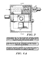
- the lining 10 of a typical prior art gasifier comprises an outer metallic shell 12, a layer of insulation 14 confronting the outer shell 12, and a lining of refractory material 16 confronting the layer of insulation 14.
- the refractory lining 16 is oriented inward toward the heat source, and in prior gasification equipment, is intended to protect the gasification apparatus from the extreme temperatures produced in the combustion chamber.
- the outer shell 12 is fabricated of a material such as 1/8" steel
- the insulation 14 is a 1-1/2" thick mineral wool block or other similar insulation
- the refractory lining 16 is a 3" thick refractory lining.
- the gasifier 18 includes a retort or outer shell 20 which is fabricated of a metal such as steel
- the retort 20 is bent, welded, or otherwise shaped and formed to provide a retort 20 having a gasification chamber 22 within the retort 20.
- the retort 20 includes a rear wall 24, a front wall 26, a base 28, and a fuel entry opening 30 in the upper region of the retort.
- a massive refractory layer 32 having an upper inclined surface is disposed along the rear wall 24 of the gasifier 18 and inclines, downward from an upper inclined ramp section 34 to a lower inclined ramp section 36.
- the inclined ramp 32 may be fabricated of any suitable refractory material, such' as HARCAST, produced by the Harbison-Walker Company.
- the refractory is cast to form a ramp 32 of desired shape.
- the ramp 32 may be fabricated of any other refractory material having similar characteristics.
- the ramp 32 is formed of refractory material of thickness typically greater than 7.5 inches.
- Biomass fuel is delivered to the gasifier 18 through a hopper 38, illustrated in Fig. 3.
- a screw conveyor 40 is employed to distribute the biomass fuel laterally across the width of the fuel delivery opening 30 located at the lower extreme of a fuel entry chamber 42.
- Biomass fuel delivered to the fuel entry chamber 42 flows by gravity feed downward through the fuel delivery opening 30 along the inclined refractory ramp 32 through a preheating zone P, a vaporization zone V, and a carbonization zone C.
- the ramp 32 is inclined from the fuel entry opening 30 at a selected angle of inclination to achieve a desired flow rate of biomass material along the ramp through the respective zones.
- a ramp 44 having an interior facing second inclined surface is disposed below the massive inclined ramp 32 and extends from the lower ramp end 36 of the ramp 32 to the base region 28 of the retort 18.
- the lower end 46 of the lower ramp 44 is oriented such that expended biomass fuel, in the form of ash, flows directly into an ash removal trough 48, located in the base region 28 of the retort 18.
- the ramp 44 is fabricated of a refractory material, such as NUCON, which is less subject to deterioration when subjected to extreme temperatures and complex chemical reactions found within the combustion zone F directly adjacent the ramp 44 than conventional metal grates.
- Air inlet holes 50 are provided in the ramp 44 in a preferred embodiment of the invention and an air plenum 52 is positioned on the rear wall 24 of the retort 20 to permit introduction of air through air inlet holes 50 of the ramp 44. Means are provided for introduction of the air at a controlled rate and pressure through the plenum 52 and air inlet holes 50.
- the massive inclined ramp 32 is oriented such that the upper surface of the ramp is inclined at a first angle "a" of inclination and the ramp 44 is oriented such that the upper surface of the ramp is inclined a second angle "b" of inclination or steepness.
- the second angle "b” of inclination or steepness is greater than the first angle "a” to achieve free and consistent flow of biomass fuel through the pre- heating, vaporization, carbonization, and combustion zones respectively.
- Biomass fuel upon pyrolysis and after carbonization within the carbonization zone C, obtains a different angle of repose, necessitating a steeper incline in accordance with the present disclosure, to achieve the desired fuel flow.
- the ramp 32 is typically provided with an angle of inclination "a" of approximately 60° and the air inlet ramp 44 is provided with an angle of inclination "b", of 70°. It is apparent that other angles of inclination are appropriate for other biomass fuels since different biomass fuels have different angles of repose.
- a massive refractory frontal layer 54 is disposed in opposed relation to the massive inclined ramp 32 and is located to confront the front wall 26 of the retort 20.
- the frontal refractory layer has an interior surface inclined at an angle substantially equivalent to the angle "a" of inclination of the first surface of the massive refractory layer 32, although this angular equivalence is not required for operation in accordance with the present invention.
- An opening 56 is provided in the frontal refractory layer 54 to permit withdrawal of volatile and combustible gases from the gasification chamber 32. Withdrawal of gases is typically achieved by means of suction induced by a fan (not shown) or any other suitable means. Volatile and combustible gases withdrawn from the gasification chamber are delivered to the fire box of a boiler, furnace, or other combustion device using gaseous or liquid fuels.
- Insulation 57 is typically provided between the massive refractory material and the outer wall of the retort 20.
- the insulation 57 serves to improve the heat retention properties of the gasifier.
- One form of insulation, known as MONOBLOCK, has been successfully employed in a preferred embodiment of the invention, although it is apparent that any suitable insulation material may be substituted.
- a tongue 58 of refractory material extends downward from the upper region and laterally across the gasification chamber 22 toward the inclined refractory ramp 32 so as to produce a constricting throat 60 between the tongue 58 and the ramp 32 along the entire width of the gasification chamber 22.
- Fuel delivered to the fuel entry chamber 42 feeds by gravity through the fuel delivery opening 30 to the throat 60 and is packed by reason of the constricting throat 60. Packing of the biomass fuel in the throat 60 region produces an air seal and precludes the undesirable introduction of air into the carbonization zone C of the gasification chamber 22. The entry of air into the carbonization zone C would result in undesirable combustion of volatile gases released in that zone, and the presence of the air seal provided in the manner indicated minimizes such disadvantageous combustion.
- the conveyor 40 which in the present embodiment is shown to be a screw conveyor.
- Biomass fuel drops downward within the fuel entry chamber 42, and, as previously discussed, is compacted due to constriction in the throat 60 region formed between the tongue 58 and the massive refractory ramp 32.
- the tongue 58 is heated from its lower frontal portion by hot gases rising from the combustion zone F, as well as by radiant heat from that zone.
- the heat conducted and radiated from the refractory tongue 58 serves fo preheat fuel in the throat 60 region and commence vaporization of remaining moisture in the biomass fuel. Free moisture is completely vaporized within the vaporization zone V located below the preheating zone P.
- the biomass fuel continues to slide downward from the vaporization zone V, it is subjected to intense radiated and reflected heat in a carbonization zone C. Radiated heat is provided by the massive refractory ramp 32, the tongue 58, and the frontal refractory layer 54. Additionally, heat generated in the combustion zone F is reflected from the frontal refractory layer 54 and back upon the fuel pile in the carbonization zone C.
- the frontal refractory layer in steady state operation, is heated to a temperature of approximately 1200-1400°F, and is incandescent.
- the frontal refractory layer 54 is angled so as to reflect heat generated within the combustion zone F directly back upon the biomass fuel pile in the carbonization zone to achieve optimum pyrolysis within the carbonization zone C.
- the frontal refractory layer 54 typically is formed of refractory material of thickness greater than 4.5 inches, and as discussed, offers significant benefits compared to gasification equipment incorporating linings of approximately 3 inches.
- the fuel As the biomass fuel slides downward along the inclined refractory ramp 32, the fuel is pyrolyzed in the carbonization zone C as discussed. By the time the fuel reaches the point of inflection 62 between the inclined refractory ramp 32 and the refractory ramp 44, the biomass fuel has been totally carbonized. Once the biomass fuel has been carbonized in the carbonization zone C, the fuel does not flow as readily as nonearbonized fueL Thus the angle of inclination or steepness of the ramp 44 is selected to maintain the flow of carbonized fuel smooth in relation to the rate of flow of fuel along the massive refractory ramp 32 above. As the carbonized fuel slides over the ramp 44, the fuel combusts in the presence of oxygen supplied through the air inlets 50 and the air plenum 52.
- Oxidation of the carbonized fuel in the combustion zone F results in the production of combustible gas, primarily in the form of carbon monoxide and amounts of noncombustible carbon dioxide.
- combustible gas primarily in the form of carbon monoxide and amounts of noncombustible carbon dioxide.
- ash Upon complete combustion of the carbonized fuel, only ash remains as a by-product of combustion, and the ash flows into the trough 48 in the base 28 of the retort 20.
- holes are provided in sidewall refractory material, or the frontal refractory layer instead of or in addition to air inlet holes provided in the ramp 44 to promote uniform combustion within the combustion zone F.
- the presently disclosed apparatus provides substantially improved gas production under conditions of varying load requirements. For example, a demand for increased gas production, momentarily results in greater combustion of carbonized fuel in the combustion zone F resulting in higher temperature in the combustion zone F. As more carbonized fuel is oxidized and reduced to ash, more fuel slides along the ramp 32 into the carbonization zone C. The greater heat generated within the combustion zone F is reflected from the frontal refractory layer 54 onto the fuel in the carbonization zone C, thereby producing greater volumes of volatile gases. The volatile gases are cooler than the combustible gases released in the combustion zone F. These cooler volatile gases lower the total gas temperature, thereby maintaining the system in balance. More specifically, more stable internal temperatures and gas compositions are maintained.
- Prior systems not incorporating massive refractory exhibited wide variations in temperature and gas composition within the gasification region 22 as a result of varying demands for gas output. Specifically, a combustion zone in some prior gasifiers might exhibit extremely hot temperatures under a demand condition while a carbonization zone exhibited undesired cooling as a consequence of greater fuel flow within the carbonization zone, thereby causing inadequate, pyrolysis under demand conditions.
- the massive refractory ramp 32 and the air inlet ramp 44 need not have planar surfaces as illustrated in the present embodiment, but may comprise curves or shapes varying to achieve the desired flow disclosed herein.
Landscapes
- Chemical & Material Sciences (AREA)
- Engineering & Computer Science (AREA)
- Combustion & Propulsion (AREA)
- Oil, Petroleum & Natural Gas (AREA)
- Organic Chemistry (AREA)
- Mechanical Engineering (AREA)
- Processing Of Solid Wastes (AREA)
- Solid-Fuel Combustion (AREA)
Applications Claiming Priority (2)
| Application Number | Priority Date | Filing Date | Title |
|---|---|---|---|
| US52836483A | 1983-08-31 | 1983-08-31 | |
| US528364 | 1983-08-31 |
Publications (2)
| Publication Number | Publication Date |
|---|---|
| EP0136277A2 true EP0136277A2 (fr) | 1985-04-03 |
| EP0136277A3 EP0136277A3 (fr) | 1986-01-08 |
Family
ID=24105392
Family Applications (1)
| Application Number | Title | Priority Date | Filing Date |
|---|---|---|---|
| EP84850250A Withdrawn EP0136277A3 (fr) | 1983-08-31 | 1984-08-27 | Gazéificateur et méthode pour produire du gaz combustible à partir de la biomasse |
Country Status (2)
| Country | Link |
|---|---|
| EP (1) | EP0136277A3 (fr) |
| FI (1) | FI843396A7 (fr) |
Cited By (3)
| Publication number | Priority date | Publication date | Assignee | Title |
|---|---|---|---|---|
| WO2003012013A1 (fr) | 2001-08-02 | 2003-02-13 | T.G.E. Tech. Ltd. | Procede et appareil de traitement des ordures menageres |
| AU2013203654B2 (en) * | 2006-10-26 | 2014-12-04 | Xyleco, Inc. | Processing biomass |
| US9023628B2 (en) | 2006-10-26 | 2015-05-05 | Xyleco, Inc. | Processing biomass |
Family Cites Families (4)
| Publication number | Priority date | Publication date | Assignee | Title |
|---|---|---|---|---|
| DE429878C (de) * | 1924-05-01 | 1926-06-04 | Rudolf Bergmans | Halbgas-Schraegrostfeuerung |
| US4030895A (en) * | 1976-03-17 | 1977-06-21 | Caughey Robert A | Apparatus for producing combustible gases from carbonaceous materials |
| US4095958A (en) * | 1977-06-21 | 1978-06-20 | Forest Fuels, Inc. | Apparatus and method for producing combustible gases from biomass material |
| US4233024A (en) * | 1978-11-20 | 1980-11-11 | Plass Vernon F | Apparatus for destructive distillation of cellulosic materials |
-
1984
- 1984-08-27 EP EP84850250A patent/EP0136277A3/fr not_active Withdrawn
- 1984-08-29 FI FI843396A patent/FI843396A7/fi not_active Application Discontinuation
Cited By (7)
| Publication number | Priority date | Publication date | Assignee | Title |
|---|---|---|---|---|
| WO2003012013A1 (fr) | 2001-08-02 | 2003-02-13 | T.G.E. Tech. Ltd. | Procede et appareil de traitement des ordures menageres |
| US7028624B2 (en) | 2001-08-02 | 2006-04-18 | T.G.E. Tech Ltd. | Method and apparatus for the treatment of domestic waste |
| AU2013203654B2 (en) * | 2006-10-26 | 2014-12-04 | Xyleco, Inc. | Processing biomass |
| US9023628B2 (en) | 2006-10-26 | 2015-05-05 | Xyleco, Inc. | Processing biomass |
| US9347661B2 (en) | 2006-10-26 | 2016-05-24 | Xyleco, Inc. | Processing biomass |
| US10287730B2 (en) | 2006-10-26 | 2019-05-14 | Xyleco, Inc. | Processing biomass |
| US10704196B2 (en) | 2006-10-26 | 2020-07-07 | Xyleco, Inc. | Processing biomass |
Also Published As
| Publication number | Publication date |
|---|---|
| FI843396A0 (fi) | 1984-08-29 |
| FI843396A7 (fi) | 1985-03-01 |
| EP0136277A3 (fr) | 1986-01-08 |
Similar Documents
| Publication | Publication Date | Title |
|---|---|---|
| CA1062012A (fr) | Appareil de production de gaz combustibles a partir de matieres carbonees | |
| CA1081954A (fr) | Appareil pour la production du gaz et methode connexe | |
| KR910007600B1 (ko) | 알카리 함유연료의 연소 방법 | |
| KR101890873B1 (ko) | 폐기물 가스화 용해로 | |
| WO1997015641A1 (fr) | Production d'energie thermique a partir de combustibles carbones solides | |
| US4480559A (en) | Coal and char burner | |
| US4749383A (en) | Method for producing low and medium BTU gas from coal | |
| JP5255510B2 (ja) | 廃棄物溶融処理方法および廃棄物溶融処理装置 | |
| US4095958A (en) | Apparatus and method for producing combustible gases from biomass material | |
| US4747355A (en) | Combustion apparatus and method of generating gas | |
| EP0136277A2 (fr) | Gazéificateur et méthode pour produire du gaz combustible à partir de la biomasse | |
| JPS5839468B2 (ja) | 連続的に運転する竪型のガス化炉およびその運転方法 | |
| US2996292A (en) | Gravity-fed combustion equipment applying crossfeed ignition principle | |
| US4781171A (en) | Gas fired particulate melting apparatus and method | |
| US2866696A (en) | Process for the gasification of granulated fluidized bed of carbonaceous material, over moving, sloping, horizontal, continuous grate | |
| US2395231A (en) | Cupola furnace | |
| WO2003025459A1 (fr) | Chaudiere et procede permettant d'extraire de l'energie d'un combustible | |
| US4058069A (en) | Process and apparatus for incinerating substances in a fluidized thermal reaction furnace | |
| US20070261616A1 (en) | solid fuel burner-gasifier methods and apparatus | |
| EP0248808B1 (fr) | Bruleur, notamment pour combustion de biomasse | |
| US3148128A (en) | Adjustable slope char oven | |
| EP0985009B1 (fr) | Procede et appareil de chauffage d'un four rotatif concu pour la gazeification et la pyrolyse d'une matiere organique | |
| CA2208835A1 (fr) | Reacteur pour le rechauffement et le traitement de materiaux en atmosphere controlee | |
| NO833932L (no) | Produksjonsanlegg for forbrennbar gass. | |
| US2694989A (en) | Apparatus for the automatic firing of solid fuel such as coke and similar fuels, and in particular relating to the firing of large coke |
Legal Events
| Date | Code | Title | Description |
|---|---|---|---|
| PUAI | Public reference made under article 153(3) epc to a published international application that has entered the european phase |
Free format text: ORIGINAL CODE: 0009012 |
|
| AK | Designated contracting states |
Designated state(s): DE FR GB SE |
|
| PUAL | Search report despatched |
Free format text: ORIGINAL CODE: 0009013 |
|
| AK | Designated contracting states |
Designated state(s): DE FR GB SE |
|
| 17P | Request for examination filed |
Effective date: 19860702 |
|
| 17Q | First examination report despatched |
Effective date: 19870805 |
|
| STAA | Information on the status of an ep patent application or granted ep patent |
Free format text: STATUS: THE APPLICATION IS DEEMED TO BE WITHDRAWN |
|
| 18D | Application deemed to be withdrawn |
Effective date: 19880416 |
|
| RIN1 | Information on inventor provided before grant (corrected) |
Inventor name: SEEL, TIMOTHY P. Inventor name: BROCHU, RICHARD R. |