EP0136324B1 - Verkleidungselement für aussenfassade und seine verwendung - Google Patents
Verkleidungselement für aussenfassade und seine verwendung Download PDFInfo
- Publication number
- EP0136324B1 EP0136324B1 EP84900989A EP84900989A EP0136324B1 EP 0136324 B1 EP0136324 B1 EP 0136324B1 EP 84900989 A EP84900989 A EP 84900989A EP 84900989 A EP84900989 A EP 84900989A EP 0136324 B1 EP0136324 B1 EP 0136324B1
- Authority
- EP
- European Patent Office
- Prior art keywords
- covering
- orifices
- returns
- return
- disposed
- Prior art date
- Legal status (The legal status is an assumption and is not a legal conclusion. Google has not performed a legal analysis and makes no representation as to the accuracy of the status listed.)
- Expired
Links
- 238000005253 cladding Methods 0.000 title abstract description 17
- 238000001125 extrusion Methods 0.000 claims abstract description 6
- 239000000463 material Substances 0.000 claims abstract description 5
- 229920002554 vinyl polymer Polymers 0.000 claims abstract 2
- 239000011810 insulating material Substances 0.000 claims description 6
- 230000003014 reinforcing effect Effects 0.000 claims description 6
- 238000009432 framing Methods 0.000 claims description 4
- 239000007859 condensation product Substances 0.000 claims description 3
- 238000005273 aeration Methods 0.000 claims 5
- 229920001169 thermoplastic Polymers 0.000 claims 3
- 239000004416 thermosoftening plastic Substances 0.000 claims 3
- 241000711981 Sais Species 0.000 claims 1
- 238000009833 condensation Methods 0.000 claims 1
- 230000005494 condensation Effects 0.000 claims 1
- 239000000047 product Substances 0.000 claims 1
- 229920003023 plastic Polymers 0.000 abstract 1
- 125000000391 vinyl group Chemical group [H]C([*])=C([H])[H] 0.000 abstract 1
- 238000009423 ventilation Methods 0.000 description 17
- 238000009413 insulation Methods 0.000 description 9
- 239000012815 thermoplastic material Substances 0.000 description 8
- 239000004800 polyvinyl chloride Substances 0.000 description 6
- 229920000915 polyvinyl chloride Polymers 0.000 description 6
- 239000012212 insulator Substances 0.000 description 5
- 239000011248 coating agent Substances 0.000 description 3
- 238000000576 coating method Methods 0.000 description 3
- 238000009434 installation Methods 0.000 description 3
- 230000000295 complement effect Effects 0.000 description 2
- 230000000284 resting effect Effects 0.000 description 2
- 239000004677 Nylon Substances 0.000 description 1
- 238000004140 cleaning Methods 0.000 description 1
- 238000005553 drilling Methods 0.000 description 1
- 230000000694 effects Effects 0.000 description 1
- 239000004794 expanded polystyrene Substances 0.000 description 1
- 238000010348 incorporation Methods 0.000 description 1
- 238000004519 manufacturing process Methods 0.000 description 1
- 238000000034 method Methods 0.000 description 1
- 229920001778 nylon Polymers 0.000 description 1
- 239000011505 plaster Substances 0.000 description 1
- 238000003825 pressing Methods 0.000 description 1
- XLYOFNOQVPJJNP-UHFFFAOYSA-N water Substances O XLYOFNOQVPJJNP-UHFFFAOYSA-N 0.000 description 1
Images



Classifications
-
- E—FIXED CONSTRUCTIONS
- E04—BUILDING
- E04F—FINISHING WORK ON BUILDINGS, e.g. STAIRS, FLOORS
- E04F13/00—Coverings or linings, e.g. for walls or ceilings
- E04F13/007—Outer coverings for walls with ventilating means
-
- B—PERFORMING OPERATIONS; TRANSPORTING
- B29—WORKING OF PLASTICS; WORKING OF SUBSTANCES IN A PLASTIC STATE IN GENERAL
- B29C—SHAPING OR JOINING OF PLASTICS; SHAPING OF MATERIAL IN A PLASTIC STATE, NOT OTHERWISE PROVIDED FOR; AFTER-TREATMENT OF THE SHAPED PRODUCTS, e.g. REPAIRING
- B29C35/00—Heating, cooling or curing, e.g. crosslinking or vulcanising; Apparatus therefor
- B29C35/16—Cooling
-
- B—PERFORMING OPERATIONS; TRANSPORTING
- B29—WORKING OF PLASTICS; WORKING OF SUBSTANCES IN A PLASTIC STATE IN GENERAL
- B29C—SHAPING OR JOINING OF PLASTICS; SHAPING OF MATERIAL IN A PLASTIC STATE, NOT OTHERWISE PROVIDED FOR; AFTER-TREATMENT OF THE SHAPED PRODUCTS, e.g. REPAIRING
- B29C48/00—Extrusion moulding, i.e. expressing the moulding material through a die or nozzle which imparts the desired form; Apparatus therefor
- B29C48/03—Extrusion moulding, i.e. expressing the moulding material through a die or nozzle which imparts the desired form; Apparatus therefor characterised by the shape of the extruded material at extrusion
- B29C48/07—Flat, e.g. panels
- B29C48/08—Flat, e.g. panels flexible, e.g. films
-
- B—PERFORMING OPERATIONS; TRANSPORTING
- B29—WORKING OF PLASTICS; WORKING OF SUBSTANCES IN A PLASTIC STATE IN GENERAL
- B29C—SHAPING OR JOINING OF PLASTICS; SHAPING OF MATERIAL IN A PLASTIC STATE, NOT OTHERWISE PROVIDED FOR; AFTER-TREATMENT OF THE SHAPED PRODUCTS, e.g. REPAIRING
- B29C48/00—Extrusion moulding, i.e. expressing the moulding material through a die or nozzle which imparts the desired form; Apparatus therefor
- B29C48/25—Component parts, details or accessories; Auxiliary operations
- B29C48/88—Thermal treatment of the stream of extruded material, e.g. cooling
- B29C48/90—Thermal treatment of the stream of extruded material, e.g. cooling with calibration or sizing, i.e. combined with fixing or setting of the final dimensions of the extruded article
-
- B—PERFORMING OPERATIONS; TRANSPORTING
- B29—WORKING OF PLASTICS; WORKING OF SUBSTANCES IN A PLASTIC STATE IN GENERAL
- B29C—SHAPING OR JOINING OF PLASTICS; SHAPING OF MATERIAL IN A PLASTIC STATE, NOT OTHERWISE PROVIDED FOR; AFTER-TREATMENT OF THE SHAPED PRODUCTS, e.g. REPAIRING
- B29C48/00—Extrusion moulding, i.e. expressing the moulding material through a die or nozzle which imparts the desired form; Apparatus therefor
- B29C48/25—Component parts, details or accessories; Auxiliary operations
- B29C48/88—Thermal treatment of the stream of extruded material, e.g. cooling
- B29C48/911—Cooling
-
- B—PERFORMING OPERATIONS; TRANSPORTING
- B29—WORKING OF PLASTICS; WORKING OF SUBSTANCES IN A PLASTIC STATE IN GENERAL
- B29C—SHAPING OR JOINING OF PLASTICS; SHAPING OF MATERIAL IN A PLASTIC STATE, NOT OTHERWISE PROVIDED FOR; AFTER-TREATMENT OF THE SHAPED PRODUCTS, e.g. REPAIRING
- B29C48/00—Extrusion moulding, i.e. expressing the moulding material through a die or nozzle which imparts the desired form; Apparatus therefor
- B29C48/25—Component parts, details or accessories; Auxiliary operations
- B29C48/88—Thermal treatment of the stream of extruded material, e.g. cooling
- B29C48/911—Cooling
- B29C48/9135—Cooling of flat articles, e.g. using specially adapted supporting means
- B29C48/915—Cooling of flat articles, e.g. using specially adapted supporting means with means for improving the adhesion to the supporting means
- B29C48/916—Cooling of flat articles, e.g. using specially adapted supporting means with means for improving the adhesion to the supporting means using vacuum
-
- B—PERFORMING OPERATIONS; TRANSPORTING
- B29—WORKING OF PLASTICS; WORKING OF SUBSTANCES IN A PLASTIC STATE IN GENERAL
- B29C—SHAPING OR JOINING OF PLASTICS; SHAPING OF MATERIAL IN A PLASTIC STATE, NOT OTHERWISE PROVIDED FOR; AFTER-TREATMENT OF THE SHAPED PRODUCTS, e.g. REPAIRING
- B29C48/00—Extrusion moulding, i.e. expressing the moulding material through a die or nozzle which imparts the desired form; Apparatus therefor
- B29C48/25—Component parts, details or accessories; Auxiliary operations
- B29C48/88—Thermal treatment of the stream of extruded material, e.g. cooling
- B29C48/919—Thermal treatment of the stream of extruded material, e.g. cooling using a bath, e.g. extruding into an open bath to coagulate or cool the material
-
- B—PERFORMING OPERATIONS; TRANSPORTING
- B29—WORKING OF PLASTICS; WORKING OF SUBSTANCES IN A PLASTIC STATE IN GENERAL
- B29C—SHAPING OR JOINING OF PLASTICS; SHAPING OF MATERIAL IN A PLASTIC STATE, NOT OTHERWISE PROVIDED FOR; AFTER-TREATMENT OF THE SHAPED PRODUCTS, e.g. REPAIRING
- B29C59/00—Surface shaping of articles, e.g. embossing; Apparatus therefor
- B29C59/02—Surface shaping of articles, e.g. embossing; Apparatus therefor by mechanical means, e.g. pressing
- B29C59/04—Surface shaping of articles, e.g. embossing; Apparatus therefor by mechanical means, e.g. pressing using rollers or endless belts
-
- E—FIXED CONSTRUCTIONS
- E04—BUILDING
- E04F—FINISHING WORK ON BUILDINGS, e.g. STAIRS, FLOORS
- E04F13/00—Coverings or linings, e.g. for walls or ceilings
- E04F13/07—Coverings or linings, e.g. for walls or ceilings composed of covering or lining elements; Sub-structures therefor; Fastening means therefor
- E04F13/08—Coverings or linings, e.g. for walls or ceilings composed of covering or lining elements; Sub-structures therefor; Fastening means therefor composed of a plurality of similar covering or lining elements
- E04F13/18—Coverings or linings, e.g. for walls or ceilings composed of covering or lining elements; Sub-structures therefor; Fastening means therefor composed of a plurality of similar covering or lining elements of organic plastics with or without reinforcements or filling materials or with an outer layer of organic plastics with or without reinforcements or filling materials; plastic tiles
-
- E—FIXED CONSTRUCTIONS
- E06—DOORS, WINDOWS, SHUTTERS, OR ROLLER BLINDS IN GENERAL; LADDERS
- E06B—FIXED OR MOVABLE CLOSURES FOR OPENINGS IN BUILDINGS, VEHICLES, FENCES OR LIKE ENCLOSURES IN GENERAL, e.g. DOORS, WINDOWS, BLINDS, GATES
- E06B1/00—Border constructions of openings in walls, floors, or ceilings; Frames to be rigidly mounted in such openings
- E06B1/04—Frames for doors, windows, or the like to be fixed in openings
- E06B1/34—Coverings, e.g. protecting against weather, for decorative purposes
- E06B1/342—Reveal covering members disposed alongside of a window frame
-
- B—PERFORMING OPERATIONS; TRANSPORTING
- B29—WORKING OF PLASTICS; WORKING OF SUBSTANCES IN A PLASTIC STATE IN GENERAL
- B29C—SHAPING OR JOINING OF PLASTICS; SHAPING OF MATERIAL IN A PLASTIC STATE, NOT OTHERWISE PROVIDED FOR; AFTER-TREATMENT OF THE SHAPED PRODUCTS, e.g. REPAIRING
- B29C48/00—Extrusion moulding, i.e. expressing the moulding material through a die or nozzle which imparts the desired form; Apparatus therefor
- B29C48/25—Component parts, details or accessories; Auxiliary operations
- B29C48/88—Thermal treatment of the stream of extruded material, e.g. cooling
- B29C48/90—Thermal treatment of the stream of extruded material, e.g. cooling with calibration or sizing, i.e. combined with fixing or setting of the final dimensions of the extruded article
- B29C48/904—Thermal treatment of the stream of extruded material, e.g. cooling with calibration or sizing, i.e. combined with fixing or setting of the final dimensions of the extruded article using dry calibration, i.e. no quenching tank, e.g. with water spray for cooling or lubrication
Definitions
- the present invention relates to a covering element for an exterior facade of a building and its application to the production of a cladding for said facade.
- Exterior thermal insulation systems are insulation systems for which the insulation is placed on the external facade of the external walls of a building, namely external concrete or masonry walls.
- an insulating covering is an external covering constituted by the assembly of prefabricated complexes which associate an insulator and an external skin, said complexes being glued and / or mechanically fixed on the support wall.
- a clothing formed of complex elements comprising one. core of an insulating material incorporated into an outer skin constituted by a clap consisting of a profile of a thermoplastic material. On its face in contact with the clapboard, the core of insulating material has raised portions forming shims to provide an air space.
- the clapboard consists of a flat central strip bordered on each lateral side by a return. One of said returns is extended by a folded part directed towards the inside of the clapboard and substantially parallel to the central strip so as to form a hook while the other return is extended by a wing directed towards the outside of the clapboard and substantially parallel to the central strip.
- Said wing is provided with orifices for the passage of the fixing screw of the clapboard to the support and also has at its end a folded part disposed on the side of the central strip and substantially parallel to the latter, said folded part forming an additional hook of that formed by the part extending the other return of the blink.
- the connection between two adjacent siding elements is carried out by engagement of the folded part extending one of the returns of a clapboard to the folded part in a complementary manner present at the end of the wing of the adjacent clapboard.
- a first drawback of this type of clothing resides in the fact that the clapboard connecting means do not allow the clapboards to be locked together, hence a risk of stalling in the event of pressure depression by the wind.
- a second drawback stems from the fact that means for evacuating the condensation products are not provided and that, if there is good ventilation between the insulating core and the clapboard thanks to the air gap formed by the parts in relief, the fact remains that ventilation or air renewal is not done satisfactorily.
- a third drawback lies in the fact that the heads for fixing the siding elements to the support are not protected from the weather.
- a fourth drawback stems from the difficulty of fitting the covering elements, for example, in the vertical U-shaped brackets for stopping around openings such as windows and doors.
- thermoplastic material of the type comprising a central strip bordered on each lateral side by a return and connecting means consisting of a latching blade associated with one of the returns , perpendicular to the central strip of the element, and a latching member constitutes by a box profile forming the other return, said profile being provided with a guide slot forming a groove and disposed parallel to the plane of the central strip of the item.
- the latching blade of an element can be forced into the guide slot of the box of an adjacent element, which ensures a connection of said adjacent elements by locking.
- the locking system chosen to connect said covering elements to each other makes it essential to use an additional wing-shaped part to fill the space left between the returns facing each other from any two adjacent elements in the locked position, this which leads to an increase in the cost of the coating on the one hand in material and on the other hand in exposure time.
- such elements are not provided with ventilation holes, which makes it difficult to renew the air space present between the covering elements and the support wall.
- the present invention provides a covering element capable of constituting a clapboard for a covering which can be fixed to the support wall both horizontally and vertically, said covering element making it possible to remedy the drawbacks of the above-mentioned covering elements.
- means allowing the fitting and fixing of the covering elements on support walls making a re-entrant or projecting angle with other support walls, without any discontinuities appearing.
- means according to the invention allow the connection of clothing parts at the level of the openings when the support wall includes them.
- the covering element according to FR-A-1 375 800 is produced by extruding a thermoplastic material, in particular polyvinyl chloride, and comprises a central strip bordered on each lateral side by a return, means of connection consisting of a latching blade disposed on one of the returns and a latching member disposed on the other return, the latching blade of the covering element being capable of cooperating with the latching member of an adja covering element cent to ensure a connection of said elements by locking, and means allowing the rigid attachment of the covering element to the wall serving as support for said covering element.
- a thermoplastic material in particular polyvinyl chloride
- the covering element is characterized in that the latching member consists of a latching blade having a shape complementary to the latching blade placed on the other return, said latching blades being directed towards the outside of the returns and being in substantially parallel planes, and in that on each of the returns is provided at least one series of orifices.
- one of the returns comprises two series of orifices arranged so that the latching blade present on this return is disposed between the two series of orifices.
- the other return preferably comprises a single series of orifices while the latching blade provided on this return is disposed between the series of orifices and the plane of the central strip of the element. .
- the cladding according to the invention is of the type comprising an insulating or insulating core, incorporated in an exterior clap, said insulator being made of a rigid insulating material and comprising raised studs arranged in staggered rows, distributed regularly over the entire outer face of said insulator and is characterized in that said studs are square, with rounded edges, and are arranged so as to have a diagonal substantially parallel to the longitudinal axis of the insulating core and in that said external flap is constituted by the coating element according to the invention, as defined in the claims.
- ventilation channels are provided in the insulating core and arranged so as to be able to be at least partially opposite the ventilation openings of the clapboard and thus to allow communication between said openings and the space between the studs.
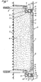
- the covering element 3 comprises an insulating core 4, or insulating material incorporated, of a rigid insulating material such as molded expanded polystyrene having a density in particular between 16 and 18 kg / m 3 and preferably fireproof, including the outer face 5 is provided with pads 6 of square shape and arranged in staggered rows (FIG. 2).
- the useful thickness of the insulation is for example between 60 and 120 mm.
- the studs 6 have a rounded edge, 10 mm thick and therefore form shims 10 mm thick.
- the insulation 4 is incorporated into a covering element constituting a clap 7, the insulating assembly 4 and clap 7 being fixed to the support wall 1 by means of complete fastening elements each comprising a dowel 8 made of nylon and a notched nail 9,
- three insulating blocks 4 are incorporated in each clapboard 7 having a useful width of approximately 300 mm for a length of the order of 3500 mm.
- the clapboard 7 is a profile obtained by extrusion, in an extruder not shown, of a thermoplastic material such as polyvinyl chloride, and is in the form of a central strip 10 bordered on each lateral side by a return or edge 11.12.
- the edges 11 and 12 will be designated respectively as being upper and lower, but it goes without saying that when the covering element 3 is arranged vertically and not horizontally, they will be left and / or right depending on the direction in which we look at them.
- the upper edge 11 comprises a reinforcing rib 13, through which are introduced the complete fixing elements 8, 9, ventilation holes 14 and hooking means constituted by an upper latching blade 15.
- the holes d 'ventilation 14 are oblong, of dimensions 8 x 32 mm for example, and regularly distributed over the entire length of the edge 11, of centers equal for example to 50 mm.
- the orifices 14 are formed on the edge 11 so as to come opposite ventilation channels 16 formed in the insulation 4.
- the channels 16 are preferably larger than the orifices 14, for example 20 x 40 mm, of so as to always have a communication between the channels 18 and the orifices 14 during the incorporation of said insulator 4 in the clapboard.
- the lower edge 12 also includes ventilation orifices 14, facing ventilation channels 16 of the 'insulator, a lower latching blade 15', and orifices 17 for evacuating condensation products or condensates.
- the blade 15 ' is disposed between the orifices 14 and 17 so that, when the blades 15 and 15' are snapped together, the condensates are prevented from entering the ventilation channels 16 of the insulation 4
- the guiding and the evacuation of the condensates towards the outside are ensured by a tongue 18 coming from extrusion and whose height is such that, when two adjacent clapboards 7 and 7 ′ or 7 ′′ are connected together, the free edge lower 19 of the tongue does not come
- a stop member 21 is provided on the lower bank 12, said member 21 being capable of coming to bear on a stop member 22 constituted by a part of the reinforcing rib 13.
- the stop members 21 and stop 22 are preferably slightly oblique so as to improve the contact between them.
- the members 21 and 22 are intended to limit any relative movement between two adjacent siding elements, the member 21 also constituting a guide during the laying of the clapboard.
- a bottom rail is installed first and serves as a level for the cladding, then the cladding elements are installed and when the last cladding element is attached, the cladding of the facade is finished with an upper beam so as to perfect the protection of clothing.
- the upper or upper rail 23 is made of an extruded thermoplastic material, such as polyvinyl chloride, and it is constituted by a hollow central rib 24 and two returns. 25 and 26.
- the return 25 is directed upwards and is fixed to the support wall 1 by means of suitable fixing elements, and in particular by means of complete fixing elements 8, 9.
- the return 26 is directed towards the bottom, therefore in the opposite direction of the return 25, and comprises a flange 27 pierced with oblong orifices 28 and bearing on the central strip of the upper clapboard. Thanks to the fact that the top rail 23 slightly covers said last clap, this ensures protection and ventilation of the last upper covering element 3, ventilation being effected through channels 16, the internal space 29 of the rail 23 and through the holes 28.
- the bottom or bottom rail 30 is also made of extruded thermoplastic material, and in particular of polyvinyl chloride, and it is constituted by a central reinforcing rib 31 and two returns 32 and 33 directed in the same direction.
- the return 32 is fixed to the support wall 1 by fixing elements, and in particular by complete fixing elements 8, 9 while the return 33, slightly elastic, comes to bear on the central strip of the first lower clap.
- On a thinner part 34 of the central rib 31 is provided a latching blade 15 cooperating with the latching blade 15 'of the adjacent clapboard, as well as ventilation openings 35 and evacuation 36 of the condensates, the ventilation and evacuation taking place through orifices 37.
- the central rib 31 also includes a free rim 38 constituting a stop member for the stop member 21 of the adjacent clapboard.
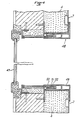
- the present invention provides an original solution to these problems by using an intermediate piece 39 as shown in FIG. 3.
- the intermediate piece 39 is the combination of the top rail 23 and the bottom rail 30, and therefore plays the role of low rail for the adjacent clap 7 located above said part 39 and the role of high rail for the adjacent clap 7 "located below said part 39.
- it comprises a reinforcing rib 40 similar to the rib 31, a return 41 analogous to the return 25 and fixed on the support wall 1, said fixing being for example made at by means of complete fastening elements 8, 9, a thinner part 42 similar to part 34 with its ventilation holes 35 and condensate drain 36 with the exception of the holes 37 and its latching blade 15, a top return 43 analogous to the return 33 and resting on the clapboard 7, and a return 44 analogous to the return 26 with its ventilation holes 28.
- a flap 46 is provided integral with the rib 40 and dest inée to serve as guide of evacuation for the condensates towards the openings 28.
- framing brackets 48 are used, made of thermoplastic material such as polyvinyl chloride and formed by profiles in two male parts 49 and female 50.
- the male part 49 comprises a fir tail 51 which allows the junction and locking of said male part in the female part 50 which is provided with a housing 52 suitable for receiving said tail of fir 51.
- Such framing brackets also include a pre-drilling and a water stop relief which allows them to be used in lintels.
- junction pieces 54 of a type analogous to that known per se from the quotation BE-A are used -688529.
- Each junction piece 54 is made up of two male 55 and female 56 parts in the form of profiles made of thermoplastic material, and in particular polyvinyl chloride.
- the male part 55 comprises two returns 57 and 58 located in perpendicular directions and, in the axis of symmetry 59 of the male part 55, a fir tail 60 locking by pressing into an appropriate housing 61 formed in the female part 56, the latter comprising also two perpendicular returns 62 and 63 fixed to the support wall by suitable fixing elements, and in particular by complete fixing elements 8, 9.
- the axis of symmetry 59 coincides with the interior bisector of the angle 53, and it is the female part 56 which is fixed to the support wall, the male part 55 taking support on the adjacent siding of the clothing.
- the procedure is the opposite, that is to say that it is the male part 55 which would be fixed on the support wall while the female part 56 would come to bear on the adjacent siding elements .
- siding elements 7, 7 ′ and 7 without specifying the surface condition of their external face.
- the siding elements in fact contribute to the aesthetics of the buildings protected by the clothing described in support of FIGS. 1 to 5. Consequently, the current trend is to give the clapboards a variable and pleasant external appearance.
- a wink having a grainy appearance, in particular an appearance of traditional plaster one can advantageously use the graining apparatus which is the subject of a divisional European patent application.
Landscapes
- Engineering & Computer Science (AREA)
- Mechanical Engineering (AREA)
- Physics & Mathematics (AREA)
- Thermal Sciences (AREA)
- Architecture (AREA)
- Civil Engineering (AREA)
- Structural Engineering (AREA)
- Health & Medical Sciences (AREA)
- Oral & Maxillofacial Surgery (AREA)
- Building Environments (AREA)
- Extrusion Moulding Of Plastics Or The Like (AREA)
- Coating Apparatus (AREA)
Claims (16)
Priority Applications (1)
| Application Number | Priority Date | Filing Date | Title |
|---|---|---|---|
| AT84900989T ATE34590T1 (de) | 1983-02-28 | 1984-02-27 | Verkleidungselement fuer aussenfassade und seine verwendung. |
Applications Claiming Priority (2)
| Application Number | Priority Date | Filing Date | Title |
|---|---|---|---|
| FR8303228A FR2541712B1 (fr) | 1983-02-28 | 1983-02-28 | Element de revetement pour facade exterieure de batiment et son application a la realisation d'une veture pour ladite facade |
| FR8303228 | 1983-02-28 |
Related Child Applications (2)
| Application Number | Title | Priority Date | Filing Date |
|---|---|---|---|
| EP87201599A Division EP0259916A3 (de) | 1983-02-28 | 1984-02-27 | Vorrichtung zum Prägen eines extrudierten thermoplastischen Profils |
| EP87201599.5 Division-Into | 1987-08-24 |
Publications (2)
| Publication Number | Publication Date |
|---|---|
| EP0136324A1 EP0136324A1 (de) | 1985-04-10 |
| EP0136324B1 true EP0136324B1 (de) | 1988-05-25 |
Family
ID=9286327
Family Applications (1)
| Application Number | Title | Priority Date | Filing Date |
|---|---|---|---|
| EP84900989A Expired EP0136324B1 (de) | 1983-02-28 | 1984-02-27 | Verkleidungselement für aussenfassade und seine verwendung |
Country Status (10)
| Country | Link |
|---|---|
| US (1) | US4686803A (de) |
| EP (1) | EP0136324B1 (de) |
| BE (1) | BE899011A (de) |
| CA (1) | CA1236959A (de) |
| DE (1) | DE3471498D1 (de) |
| ES (1) | ES530120A0 (de) |
| FR (1) | FR2541712B1 (de) |
| IT (1) | IT8419817A0 (de) |
| LU (1) | LU85230A1 (de) |
| WO (1) | WO1984003320A1 (de) |
Families Citing this family (30)
| Publication number | Priority date | Publication date | Assignee | Title |
|---|---|---|---|---|
| CH648888A5 (de) * | 1982-09-07 | 1985-04-15 | Haering & Kies Ag | Hinterlueftete isolierfassade. |
| FR2607171B1 (fr) * | 1986-11-24 | 1991-08-30 | Smac Acieroid | Lisse pour revetement de facade et revetement de facade utilisant de telles lisses |
| FR2649599B1 (fr) * | 1989-07-17 | 1995-06-02 | Guillou Alexandre | Meubles refrigeres |
| FR2667096B1 (fr) * | 1990-09-25 | 1998-01-30 | Debuschere Ets | Structure de revetement exterieur d'un batiment par une peau composite rapportee. |
| FR2720093B1 (fr) * | 1994-05-20 | 1996-07-26 | Neurone Soc Civ | Parement en matériau composite pour la réalisation d'un revêtement de façade. |
| US5918427A (en) * | 1996-10-04 | 1999-07-06 | Vanderwerf; Pieter A. | Termite shield for permeable sheathing |
| US6199334B1 (en) | 1998-02-25 | 2001-03-13 | Michael J. Malloy | Composite cladding system |
| US6101767A (en) * | 1998-06-10 | 2000-08-15 | Chem Link, Inc. | Structural termination system |
| US20020139059A1 (en) * | 2001-03-13 | 2002-10-03 | Zimmerman David L. | Device which secures external walls and components of a room and which has improved drainage capabilities and aesthetics |
| WO2003018924A1 (en) * | 2001-08-28 | 2003-03-06 | David Peter Dickinson | Cladding member and/or a cladding system and/or a method of cladding |
| US6584746B1 (en) * | 2002-05-10 | 2003-07-01 | Hohmann & Barnard, Inc. | Masonry flashing system |
| US7823355B1 (en) | 2002-05-10 | 2010-11-02 | Mitek Holdings, Inc. | Nonmetallic masonry flashing |
| US7882673B1 (en) | 2003-04-30 | 2011-02-08 | Mitek Holdings, Inc. | Single-ply masonry flashing |
| US8091313B2 (en) * | 2003-10-15 | 2012-01-10 | Progressive Foam Technologies, Inc. | Drainage place for exterior wall product |
| US7762040B2 (en) * | 2004-08-12 | 2010-07-27 | Progressive Foam Technologies, Inc. | Insulated fiber cement siding |
| US8844233B2 (en) * | 2004-08-12 | 2014-09-30 | Progressive Foam Technologies, Inc. | Foam insulation board with edge sealer |
| US8910443B2 (en) | 2004-08-12 | 2014-12-16 | Progressive Foam Technologies, Inc. | Foam backer for insulation |
| US8857123B2 (en) | 2004-08-12 | 2014-10-14 | Progressive Foam Technologies, Inc. | Foam insulation board |
| US8910444B2 (en) | 2004-08-12 | 2014-12-16 | Progressive Foam Technologies, Inc. | Foam insulation backer board |
| US8186119B1 (en) * | 2006-12-21 | 2012-05-29 | Mitek Holdings, Inc. | Thermal isolating housing structure |
| EP2137358A1 (de) * | 2007-03-21 | 2009-12-30 | James Hardie International Finance B.V. | Rahmenwandkonstruktion und verfahren |
| US20090056241A1 (en) * | 2007-08-28 | 2009-03-05 | Juergen Koessler | Moisture management systems and methods for building openings |
| US20090183453A1 (en) * | 2008-01-21 | 2009-07-23 | Juergen Koessler | Apparatus for providing air flow in a building wall |
| US8111813B2 (en) * | 2008-09-30 | 2012-02-07 | Avaya Inc. | Unified greeting service for telecommunications events |
| MX368074B (es) | 2015-01-23 | 2019-09-17 | Mitek Holdings Inc | Montaje de panel aislado. |
| US10316516B2 (en) | 2017-01-23 | 2019-06-11 | Mitek Holdings, Inc. | Insulated panel assembly |
| US10753099B2 (en) | 2018-06-20 | 2020-08-25 | Jerry D. O'Neal | Siding attachment system |
| US10550578B2 (en) * | 2018-06-20 | 2020-02-04 | Jerry D. O'Neal | Siding attachment system |
| US20210214933A1 (en) * | 2018-08-13 | 2021-07-15 | Building IP Holdings Pty Ltd | A Flashing Connector |
| FR3103506B1 (fr) | 2019-11-25 | 2021-12-03 | Sermeca Stephanoise | dispositif de vêture mobile pour bâtiments industriels de grande hauteur jusque 30 mètres de haut |
Family Cites Families (20)
| Publication number | Priority date | Publication date | Assignee | Title |
|---|---|---|---|---|
| CA688713A (en) * | 1964-06-16 | Aluminum Company Of America | Metallic sheathing | |
| US1882529A (en) * | 1931-03-02 | 1932-10-11 | Emil F Thulin | Covering for walls |
| US1998425A (en) * | 1934-07-28 | 1935-04-16 | United States Gypsum Co | Acoustical building construction |
| US2209283A (en) * | 1939-11-02 | 1940-07-23 | Peter A Parker | Building unit |
| BE531202A (de) * | 1953-08-21 | |||
| CH433029A (de) * | 1958-11-04 | 1967-03-31 | Menziken Aluminium Ag | Profilschienen aufweisende Wand |
| US3001332A (en) * | 1959-01-23 | 1961-09-26 | Shepard J Wilder | Ventilating devices for hollow building walls |
| US3233382A (en) * | 1962-08-30 | 1966-02-08 | Alside Inc | Aluminum siding panel having interlocking marginal edges |
| US3214876A (en) * | 1962-12-10 | 1965-11-02 | Mastic Corp | Nail anchored building siding |
| FR1375800A (fr) * | 1963-08-02 | 1964-10-23 | Disposition des revêtements pour les murs extérieurs des bâtiments ou similaires | |
| BE688529A (de) * | 1966-10-19 | 1967-03-31 | ||
| NL162167B (nl) * | 1968-01-05 | 1969-07-08 | Carl Rosenthal | Ruitsponningprofiel met condensgoot. |
| FR1599637A (de) * | 1968-05-11 | 1970-07-15 | ||
| AT323964B (de) * | 1971-11-02 | 1975-08-11 | Haas Ernst | Fassadenplatte |
| DE2418009A1 (de) * | 1973-04-16 | 1974-10-31 | Pjk Projects Ltd | Vorgefertigte paneeltafel zur herstellung von wandpaneelen |
| DE2447489A1 (de) * | 1974-10-04 | 1976-04-08 | Aluminiumwerke Ag Rorschach | Wasserdampfdurchlaessige verkleidung |
| JPS553265Y2 (de) * | 1974-12-26 | 1980-01-25 | ||
| US4454863A (en) * | 1976-08-30 | 1984-06-19 | Brown Donald P | Solar heat collecting panel assembly and method for covering structures |
| DE2900583A1 (de) * | 1979-01-09 | 1980-07-17 | Jun Bernd Seitner | Verfahren zur herstellung von druckfesten isoliertapeten und -platten |
| US4327528A (en) * | 1980-02-29 | 1982-05-04 | Wolverine Aluminum Corporation | Insulated siding system |
-
1983
- 1983-02-28 FR FR8303228A patent/FR2541712B1/fr not_active Expired
-
1984
- 1984-02-27 WO PCT/FR1984/000040 patent/WO1984003320A1/fr not_active Ceased
- 1984-02-27 BE BE0/212454A patent/BE899011A/fr unknown
- 1984-02-27 US US06/677,545 patent/US4686803A/en not_active Expired - Fee Related
- 1984-02-27 EP EP84900989A patent/EP0136324B1/de not_active Expired
- 1984-02-27 LU LU85230A patent/LU85230A1/fr unknown
- 1984-02-27 CA CA000448353A patent/CA1236959A/fr not_active Expired
- 1984-02-27 DE DE8484900989T patent/DE3471498D1/de not_active Expired
- 1984-02-28 ES ES530120A patent/ES530120A0/es active Granted
- 1984-02-28 IT IT8419817A patent/IT8419817A0/it unknown
Also Published As
| Publication number | Publication date |
|---|---|
| LU85230A1 (fr) | 1984-10-26 |
| IT8419817A0 (it) | 1984-02-28 |
| FR2541712A1 (fr) | 1984-08-31 |
| ES8507647A1 (es) | 1985-09-16 |
| DE3471498D1 (en) | 1988-06-30 |
| CA1236959A (fr) | 1988-05-24 |
| BE899011A (fr) | 1984-06-18 |
| ES530120A0 (es) | 1985-09-16 |
| EP0136324A1 (de) | 1985-04-10 |
| FR2541712B1 (fr) | 1986-01-31 |
| WO1984003320A1 (fr) | 1984-08-30 |
| US4686803A (en) | 1987-08-18 |
Similar Documents
| Publication | Publication Date | Title |
|---|---|---|
| EP0136324B1 (de) | Verkleidungselement für aussenfassade und seine verwendung | |
| EP0088658A1 (de) | Befestigungsvorrichtung für eine Kunststeinplattenverkleidung auf einer Wand | |
| FR2693849A1 (fr) | Ensemble profilé composite de type goulotte ou analogue. | |
| FR2466581A1 (fr) | Latte pour toiture | |
| FR2717842A1 (fr) | Faux plafond comportant une armature suspendue pourvue d'éléments décoratifs, et armature suspendue pour ce faux plafond. | |
| EP1282753A1 (de) | Befestigungsvorrichtung für die längsränder von platten, latten oder wandverkleidungen mit kraftverteilung | |
| EP0783064B1 (de) | Verbundprofilelement und mit diesem hergestellte Trennwand | |
| EP0354149A1 (de) | Verfahren und Vorrichtung zum dichten Verbinden von Beregnung ausgesetzten Platten | |
| EP0030508A1 (de) | Paneel für die Verkleidung von Gebäudefassaden | |
| EP0271400B1 (de) | Fassadeverkleidung mit ventilierter Luftschicht | |
| EP0373017A1 (de) | Mit Fliesen ausgerüstetes Einkleidungselement zum Abführen des Kondenswassers | |
| EP0559292A1 (de) | Anschlusselement für Bauprofile und Konstruktionen, die mittels solcher Anschlusselemente verbundene Bauprofile enthalten | |
| FR2541707A1 (fr) | Cloison amovible a montage et a demontage rapides | |
| EP2116657A1 (de) | Holzkonstruktionssystem mit doppelter Dichtungsbarriere | |
| FR2878875A1 (fr) | Module pour l'habillage de plafonds et de murs | |
| EP0120788A1 (de) | Zusammensetzung in einer thermischen Aussenisolation | |
| FR2479878A1 (fr) | Revetement compose de bardeaux encastres sur profils | |
| FR3094021A1 (fr) | Closoir ventilé pour toiture | |
| CA1229710A (fr) | Appareillage de grainage d'un profile | |
| FR2713260A1 (fr) | Baguette destinée à être fixée sur une paroi portant un revêtement. | |
| FR2873140A1 (fr) | Socle profile pour barre de seuil | |
| EP3388592A1 (de) | Selbsttragende dachplatte | |
| EP0791700A1 (de) | Befestigungshalterung und Abstandhalter zur Erstellung von Verkleidungen im Bausektor, und so hergestellte Verkleidungen | |
| EP0120751B1 (de) | Durch Luftströmung belüftete Verkleidung | |
| FR2808824A1 (fr) | Dispositif d'assemblage des bords longitudinaux de panneaux, lattes ou lambris, a repartition de forces |
Legal Events
| Date | Code | Title | Description |
|---|---|---|---|
| PUAI | Public reference made under article 153(3) epc to a published international application that has entered the european phase |
Free format text: ORIGINAL CODE: 0009012 |
|
| 17P | Request for examination filed |
Effective date: 19841018 |
|
| AK | Designated contracting states |
Designated state(s): AT CH DE FR GB LI NL SE |
|
| GRAA | (expected) grant |
Free format text: ORIGINAL CODE: 0009210 |
|
| RAP1 | Party data changed (applicant data changed or rights of an application transferred) |
Owner name: ELFISOL |
|
| RAP1 | Party data changed (applicant data changed or rights of an application transferred) |
Owner name: EFISOL |
|
| AK | Designated contracting states |
Kind code of ref document: B1 Designated state(s): AT CH DE FR GB LI NL SE |
|
| REF | Corresponds to: |
Ref document number: 34590 Country of ref document: AT Date of ref document: 19880615 Kind code of ref document: T |
|
| REF | Corresponds to: |
Ref document number: 3471498 Country of ref document: DE Date of ref document: 19880630 |
|
| GBT | Gb: translation of ep patent filed (gb section 77(6)(a)/1977) | ||
| PLBE | No opposition filed within time limit |
Free format text: ORIGINAL CODE: 0009261 |
|
| STAA | Information on the status of an ep patent application or granted ep patent |
Free format text: STATUS: NO OPPOSITION FILED WITHIN TIME LIMIT |
|
| 26N | No opposition filed | ||
| PGFP | Annual fee paid to national office [announced via postgrant information from national office to epo] |
Ref country code: CH Payment date: 19941227 Year of fee payment: 12 Ref country code: SE Payment date: 19941227 Year of fee payment: 12 |
|
| EAL | Se: european patent in force in sweden |
Ref document number: 84900989.9 |
|
| PGFP | Annual fee paid to national office [announced via postgrant information from national office to epo] |
Ref country code: GB Payment date: 19950217 Year of fee payment: 12 |
|
| PGFP | Annual fee paid to national office [announced via postgrant information from national office to epo] |
Ref country code: AT Payment date: 19950228 Year of fee payment: 12 |
|
| PG25 | Lapsed in a contracting state [announced via postgrant information from national office to epo] |
Ref country code: GB Effective date: 19960227 Ref country code: AT Effective date: 19960227 |
|
| PG25 | Lapsed in a contracting state [announced via postgrant information from national office to epo] |
Ref country code: SE Effective date: 19960228 |
|
| PG25 | Lapsed in a contracting state [announced via postgrant information from national office to epo] |
Ref country code: LI Effective date: 19960229 Ref country code: CH Effective date: 19960229 |
|
| REG | Reference to a national code |
Ref country code: CH Ref legal event code: PL |
|
| GBPC | Gb: european patent ceased through non-payment of renewal fee |
Effective date: 19960227 |
|
| PGFP | Annual fee paid to national office [announced via postgrant information from national office to epo] |
Ref country code: NL Payment date: 20010228 Year of fee payment: 18 |
|
| PGFP | Annual fee paid to national office [announced via postgrant information from national office to epo] |
Ref country code: DE Payment date: 20010426 Year of fee payment: 18 |
|
| PGFP | Annual fee paid to national office [announced via postgrant information from national office to epo] |
Ref country code: FR Payment date: 20020227 Year of fee payment: 19 |
|
| PG25 | Lapsed in a contracting state [announced via postgrant information from national office to epo] |
Ref country code: NL Free format text: LAPSE BECAUSE OF NON-PAYMENT OF DUE FEES Effective date: 20020901 |
|
| PG25 | Lapsed in a contracting state [announced via postgrant information from national office to epo] |
Ref country code: DE Free format text: LAPSE BECAUSE OF NON-PAYMENT OF DUE FEES Effective date: 20020903 |
|
| NLV4 | Nl: lapsed or anulled due to non-payment of the annual fee |
Effective date: 20020901 |
|
| PG25 | Lapsed in a contracting state [announced via postgrant information from national office to epo] |
Ref country code: FR Free format text: LAPSE BECAUSE OF NON-PAYMENT OF DUE FEES Effective date: 20031031 |
|
| REG | Reference to a national code |
Ref country code: FR Ref legal event code: ST |