EP0136413A2 - Automatisches Raumkoordinatenkalibriersystem eines Robotergreifers mit sechs Freiheitsgraden - Google Patents
Automatisches Raumkoordinatenkalibriersystem eines Robotergreifers mit sechs Freiheitsgraden Download PDFInfo
- Publication number
- EP0136413A2 EP0136413A2 EP84107438A EP84107438A EP0136413A2 EP 0136413 A2 EP0136413 A2 EP 0136413A2 EP 84107438 A EP84107438 A EP 84107438A EP 84107438 A EP84107438 A EP 84107438A EP 0136413 A2 EP0136413 A2 EP 0136413A2
- Authority
- EP
- European Patent Office
- Prior art keywords
- robot
- gripper
- cube
- compensate
- coordinate
- Prior art date
- Legal status (The legal status is an assumption and is not a legal conclusion. Google has not performed a legal analysis and makes no representation as to the accuracy of the status listed.)
- Granted
Links
Images





Classifications
-
- B—PERFORMING OPERATIONS; TRANSPORTING
- B25—HAND TOOLS; PORTABLE POWER-DRIVEN TOOLS; MANIPULATORS
- B25J—MANIPULATORS; CHAMBERS PROVIDED WITH MANIPULATION DEVICES
- B25J9/00—Program-controlled manipulators
- B25J9/16—Program controls
- B25J9/1679—Program controls characterised by the tasks executed
- B25J9/1692—Calibration of manipulator
Definitions
- the invention relates to a system for automatically compensating positioning errors of a robot gripper in all degrees of freedom in a robot or like system.
- the robot gripper is under computer control programmed to successively and repeatedly be positioned and operated in predetermined positions within the work envelope of the robot.
- IBM Robot System/l General Information Manual and User's Guide which describes such a robot system in detail.
- U.S. Pat.No. 4.362.977 describes such a method and apparatus for calibration of a robot and using the results of the calibration to compensate for inaccuracies of the robot.
- the method includes moving the robot gripper to a set of nominal positions, commanded by the robot controller or measured by position encoders built into the robot, and determining the associated actual positions by measuring the robot position with an independent accurate measuring means or by aligning the robot end effector with an accurate calibration mask.
- the calibration results are stored and subsequently used to compensate for robot inaccuracy so that the robot moves to the actual desired positions.
- the invention as claimed is intended to remedy the above mentioned drawbacks. It solves the problem by iteratively compensating for the errors in the different coordinate directions of movement of the robot gripper. This is performed by letting the robot gripper position a measuring body in a calibrating position within a measuring fixture which is fixedly mounted to the robot frame.
- the measuring body may, for example, consist of three cube surfaces which are exactly defined in relation to the gripper definition point.
- the measuring fixture may, for example, consist of an array of sensing means which are positioned in three surfaces of the measuring fixture corresponding to the above mentioned three surfaces of the measuring body.
- the difference in two suitably chosen sensor values are used for iteratively compensating the robot gripper in an associated angular coordinate direction (P).
- the pairs of equal sensor values are compared with nominal values in order to iteratively compensate the robot gripper in the orthogonal coordinate directions.
- the errors in respective coordinate directions P,a, 7 ,x, y and z may be sucessively calculated and the calculated error values used to sucessively compensate for the errors in the different coordinate directions.
- Figure 1 is an isometric view of a robot system.
- a robot gripper (1) operates under computer control within the work envelope 2 (shown in phantom) of the robot.
- the gripper is movable in six coordinate directions, a, ⁇ , y, x, y and z, where a is the yaw coordinate, ⁇ is the pitch coordinate and ⁇ is the circum gyrate coordinate.
- Tools and materials are positioned on a work table 3 fixedly mounted to the robot frame 4. These tools and materials are positioned on the work table in exactly defined positions to allow the robot gripper to find and handle them.
- the work space of the robot is defined by a robot coordinate system (x,y,z).
- the gripper At the start up of a new work process the gripper must first be calibrated and compensated, that means, to be positioned in a start position which is exactly defined in the robot coordinate system. From that position the robot gripper can start to operate under computer program control. Besides, during the work process of the robot, errors in the positioning of the gripper may occur due to drift in some or all of the six coordinate directions. Then, malfunction of the.robot operation may occur if the gripper does not find the tool or material needed. Therefore, compensation of the robot coordinates at suitable time intervals is a requisite.
- Fig. 2 shows an isometric view of a robot proyided with a calibration device 21 shown in schematic form.
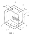
- the calibration device consists of two main parts (see also fig. 3), a first part 31 fixed to the robot frame and a second part, a cube formed measuring body 32 which is gripped by-the gripper.
- This second part may be positioned in a suitable position within the work envelope of the robot.
- the gripper grips the second part and moves it into the calibrating position within said first part of the calibration device.
- the second part is springingly mounted in a position within said first part 31.
- the second part is described more in detail below.
- the fixed part of the calibration device consists of three walls AAF, BBF and CCF of a cube 31.
- the fixed part is provided with sensing means S1-S6 (indicated in phantom) for determining the position in space of said second part 32, the measuring body, during calibration.
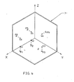
- the positions, P1-P6, of the sensors S may be as indicated in fig. 4 or in other suitable positions.
- Six such sensors are used to define the position in space of the measuring body.
- the distribution is two in surface (wall) AAF, two in surface (wall) BBF and two in surface (wall) CCF.
- the sensors are placed perpendicular to respective surfaces in positions defined for S1-S2 in the x-y-plane, for S3 - S4 in the x-z-plane and for S5-S6 in the y-z-plane of the robot coordinate system as indicated in phantom in fig. 4.
- Said first calibration part 31 is fixedly mounted to the robot frame in such a way that its coordinate axis x, y, z is exactly parallel to or coinciding with (fig. 5) respective coordinate axis x, y and z in fig. 1.
- Fig. 5a shows the relations between the different coordinate systems used.
- a home coordinate system (xHO, yHO, zHO) for the measuring body, the measuring cube, is indicated in dashed lines in fig. 5a.
- the cube central home coordinate system (xCHO, yCHO, zCHO) that is, a coordinate system coinciding with the cube central coordinate system, when the cube is in its home position.
- the central cube coordinate system (xC, yC, zC) has its origo in the central point of the measuring cube and has its axes perpendicular to the cube surfaces.
- Fig. 6 shows the intersectional points PEE, PDD and PFF between the positive cube central coordinate x-axis, y-axis and z-axis and the imaginary cube surfaces EE, DD and FF, respectively.
- the joint point PJJ is situated on the yC-axis of the cube.
- Fig. 7 is a separate view of the measuring cube.
- the cube is provided with an intermediate wall 33 having a guiding profile 34 for guiding the cube definition point 35 to coincide with the gripper definition point 35 when the gripper grips the cube.
- the robot gripper grips under computer program control the measuring body 32 and moves of into a calibrating position within the measuring fixture 31.
- the robot gripper grips the measuring body 32 in a premeasuring position within the measuring fixture 31.
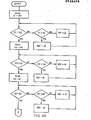
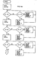
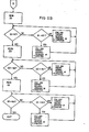
- the compensating process is performed by the following main steps a-g;
- the compensating process is performed by the following main steps k-q);
Landscapes
- Engineering & Computer Science (AREA)
- Robotics (AREA)
- Mechanical Engineering (AREA)
- Manipulator (AREA)
- Numerical Control (AREA)
Applications Claiming Priority (2)
| Application Number | Priority Date | Filing Date | Title |
|---|---|---|---|
| SE8304100A SE8304100L (sv) | 1983-07-22 | 1983-07-22 | System for automatisk kalibrering av rymdkoordinaterna hos en robotgripper i sex frihetsgrader |
| SE8304100 | 1983-07-22 |
Publications (3)
| Publication Number | Publication Date |
|---|---|
| EP0136413A2 true EP0136413A2 (de) | 1985-04-10 |
| EP0136413A3 EP0136413A3 (en) | 1985-07-24 |
| EP0136413B1 EP0136413B1 (de) | 1987-06-24 |
Family
ID=20352039
Family Applications (1)
| Application Number | Title | Priority Date | Filing Date |
|---|---|---|---|
| EP84107438A Expired EP0136413B1 (de) | 1983-07-22 | 1984-06-28 | Automatisches Raumkoordinatenkalibriersystem eines Robotergreifers mit sechs Freiheitsgraden |
Country Status (8)
| Country | Link |
|---|---|
| US (1) | US4642781A (de) |
| EP (1) | EP0136413B1 (de) |
| JP (1) | JPS6025680A (de) |
| DE (1) | DE3464338D1 (de) |
| DK (1) | DK357784A (de) |
| FI (1) | FI76276C (de) |
| NO (1) | NO158786C (de) |
| SE (1) | SE8304100L (de) |
Cited By (5)
| Publication number | Priority date | Publication date | Assignee | Title |
|---|---|---|---|---|
| EP0135494A3 (en) * | 1983-07-28 | 1986-12-17 | Polaroid Corporation | Combination photodetector array/mask positioning system |
| EP0223862A4 (de) * | 1985-05-31 | 1987-07-16 | Fanuc Ltd | Vorrichtung zum einstellen eines roboters in eine referenzlage. |
| EP0313775A1 (de) * | 1987-10-08 | 1989-05-03 | Siemens Aktiengesellschaft | Berührungsloses Messsystem für Genauigkeitskenngrössen, insbesondere von Industrierobotern |
| EP0381185A3 (de) * | 1989-02-01 | 1990-10-03 | Hitachi, Ltd. | Verfahren und Vorrichtung zur Kontrolle der Bearbeitungsspur eines Industrieroboters |
| WO1993011915A1 (en) * | 1991-12-10 | 1993-06-24 | Asea Brown Boveri Ab | Method and device for calibration of movement axes of an industrial robot |
Families Citing this family (16)
| Publication number | Priority date | Publication date | Assignee | Title |
|---|---|---|---|---|
| US4831549A (en) * | 1987-07-28 | 1989-05-16 | Brigham Young University | Device and method for correction of robot inaccuracy |
| US4939678A (en) * | 1987-11-19 | 1990-07-03 | Brown & Sharpe Manufacturing Company | Method for calibration of coordinate measuring machine |
| US4892457A (en) * | 1988-07-11 | 1990-01-09 | Gmf Robotics Corporation | Apparatus for mastering a robot |
| US4967370A (en) * | 1988-10-21 | 1990-10-30 | Robotic Vision Systems, Inc. | Robot and sensor error determination system |
| US5105368A (en) * | 1990-08-01 | 1992-04-14 | At&T Bell Laboratories | Method for improving robot accuracy |
| US5392384A (en) * | 1991-04-09 | 1995-02-21 | Kabushiki Kaisha Yaskawa Denki | Method of calibrating an industrial robot |
| US5535306A (en) * | 1993-01-28 | 1996-07-09 | Applied Materials Inc. | Self-calibration system for robot mechanisms |
| US5740328A (en) * | 1996-08-12 | 1998-04-14 | The Regents Of The University Of California | Apparatus for robotic positional referencing and calibration |
| US6070109A (en) * | 1998-03-10 | 2000-05-30 | Fanuc Robotics North America, Inc. | Robot calibration system |
| US6571148B1 (en) | 2000-05-03 | 2003-05-27 | The Boeing Company | System for automatically certifying the accuracy of a manufacturing machine and associated methods |
| SE529122C2 (sv) * | 2004-09-24 | 2007-05-02 | Jokab Safety Ab | Skyddsanordning för områdesbegränsning och övervakning |
| CA2646390C (en) * | 2006-02-17 | 2014-09-23 | Oceaneering International, Inc. | A multi-mode manipulator arm and drive system |
| EP1984642A2 (de) * | 2006-02-17 | 2008-10-29 | Oceaneering International, Inc. | Manipulator und antriebssystem mit variablem modus |
| KR100871857B1 (ko) * | 2007-06-11 | 2008-12-03 | 성균관대학교산학협력단 | 차량 내부의 네트워크 시스템 및 그 제어방법 |
| WO2011163184A1 (en) * | 2010-06-22 | 2011-12-29 | Siemens Healthcare Diagnostics Inc. | Methods, systems, and apparatus for calibration of a positional offset between an end effector and a position sensor |
| TWI754888B (zh) * | 2020-01-21 | 2022-02-11 | 財團法人工業技術研究院 | 校準方法及校準系統 |
Family Cites Families (12)
| Publication number | Priority date | Publication date | Assignee | Title |
|---|---|---|---|---|
| US3526886A (en) * | 1968-03-26 | 1970-09-01 | Westinghouse Air Brake Co | Precision location detector |
| US3795054A (en) * | 1970-08-13 | 1974-03-05 | American Welding Mfg Co | Method and apparatus for calibrating the position of a tool and for gauging the dimension of a workpiece |
| JPS5425196B2 (de) * | 1972-03-16 | 1979-08-25 | ||
| JPS51141165A (en) * | 1975-05-29 | 1976-12-04 | Toshiba Corp | Reference position adjusting system for industrial robot |
| US4140953A (en) * | 1976-03-03 | 1979-02-20 | Unimation, Inc. | Real time program modification apparatus |
| GB2045461A (en) * | 1979-03-22 | 1980-10-29 | Hall Automation Ltd | Servo control system |
| US4362977A (en) * | 1980-06-30 | 1982-12-07 | International Business Machines Corporation | Method and apparatus for calibrating a robot to compensate for inaccuracy of the robot |
| US4356554A (en) * | 1980-09-12 | 1982-10-26 | Thermwood Corporation | Method and apparatus for compensating for system error in an industrial robot control |
| US4403281A (en) * | 1981-04-03 | 1983-09-06 | Cincinnati Milacron Industries, Inc. | Apparatus for dynamically controlling the tool centerpoint of a robot arm off a predetermined path |
| US4372721A (en) * | 1981-05-18 | 1983-02-08 | Nordson Corporation | Apparatus for calibrating link position transducers of a teaching robot and a work robot |
| EP0076135A3 (de) * | 1981-09-28 | 1984-05-09 | Hitachi, Ltd. | Handhabungsgerät für Gegenstände |
| US4486843A (en) * | 1982-03-03 | 1984-12-04 | Nordson Corporation | Transitional command position modification for a controller |
-
1983
- 1983-07-22 SE SE8304100A patent/SE8304100L/ not_active Application Discontinuation
-
1984
- 1984-06-20 JP JP59125444A patent/JPS6025680A/ja active Granted
- 1984-06-28 DE DE8484107438T patent/DE3464338D1/de not_active Expired
- 1984-06-28 EP EP84107438A patent/EP0136413B1/de not_active Expired
- 1984-07-09 US US06/628,922 patent/US4642781A/en not_active Expired - Fee Related
- 1984-07-16 FI FI842846A patent/FI76276C/fi not_active IP Right Cessation
- 1984-07-16 NO NO842907A patent/NO158786C/no unknown
- 1984-07-20 DK DK357784A patent/DK357784A/da not_active Application Discontinuation
Cited By (5)
| Publication number | Priority date | Publication date | Assignee | Title |
|---|---|---|---|---|
| EP0135494A3 (en) * | 1983-07-28 | 1986-12-17 | Polaroid Corporation | Combination photodetector array/mask positioning system |
| EP0223862A4 (de) * | 1985-05-31 | 1987-07-16 | Fanuc Ltd | Vorrichtung zum einstellen eines roboters in eine referenzlage. |
| EP0313775A1 (de) * | 1987-10-08 | 1989-05-03 | Siemens Aktiengesellschaft | Berührungsloses Messsystem für Genauigkeitskenngrössen, insbesondere von Industrierobotern |
| EP0381185A3 (de) * | 1989-02-01 | 1990-10-03 | Hitachi, Ltd. | Verfahren und Vorrichtung zur Kontrolle der Bearbeitungsspur eines Industrieroboters |
| WO1993011915A1 (en) * | 1991-12-10 | 1993-06-24 | Asea Brown Boveri Ab | Method and device for calibration of movement axes of an industrial robot |
Also Published As
| Publication number | Publication date |
|---|---|
| NO842907L (no) | 1985-01-23 |
| DE3464338D1 (en) | 1987-07-30 |
| NO158786B (no) | 1988-07-25 |
| NO158786C (no) | 1988-11-02 |
| SE8304100L (sv) | 1985-01-23 |
| FI76276B (fi) | 1988-06-30 |
| EP0136413A3 (en) | 1985-07-24 |
| FI76276C (fi) | 1988-10-10 |
| JPH0429515B2 (de) | 1992-05-19 |
| SE8304100D0 (sv) | 1983-07-22 |
| JPS6025680A (ja) | 1985-02-08 |
| DK357784A (da) | 1985-01-23 |
| US4642781A (en) | 1987-02-10 |
| FI842846A0 (fi) | 1984-07-16 |
| EP0136413B1 (de) | 1987-06-24 |
| DK357784D0 (da) | 1984-07-20 |
| FI842846A7 (fi) | 1985-01-23 |
Similar Documents
| Publication | Publication Date | Title |
|---|---|---|
| EP0136413A2 (de) | Automatisches Raumkoordinatenkalibriersystem eines Robotergreifers mit sechs Freiheitsgraden | |
| EP0132616B1 (de) | System zur automatischen Kalibrierung der Raumkoordinaten eines Robotgreifers in sechs Freiheitsgraden | |
| US4815006A (en) | Method and device for calibrating a sensor on an industrial robot | |
| EP2547490B1 (de) | Kalibrierung eines basiskoordinatensystems für einen industrieroboter | |
| JP5459486B2 (ja) | ロボットのキャリブレーション方法および装置 | |
| EP1936458B1 (de) | Vorrichtung, Verfahren, Programm und Aufzeichnungsmedium zur Offlineprogrammierung von Robotern | |
| EP2208572B1 (de) | Verfahren und vorrichtung zur herstellung einer fehlertabelle und numerisch gesteuerte werkzeugmaschine mit einer fehlertabellenherstellungsfunktion | |
| US5239855A (en) | Positional calibration of robotic arm joints relative to the gravity vector | |
| JP3326175B2 (ja) | 産業用ロボットの運動軸の較正方法及び装置 | |
| JP2651251B2 (ja) | スカラ型ロボットの機構誤差補正方法 | |
| US4722063A (en) | Method of calculating actual arm lengths and compensating for angular errors | |
| EP1474271A1 (de) | Kalibrierung der position und ausrichtung eines roboterbearbeitungswerkzeugs | |
| EP1899774A1 (de) | Programmgesteuerter prozess | |
| US4542467A (en) | Method of operating a machine tool with a sensing probe in order to gather positional data for the calculation of tool offset parameters | |
| JPH06131032A (ja) | ロボット装置およびロボット装置のティ−チング方法。 | |
| CN116457158A (zh) | 用于校准并联运动学机构的方法和装置 | |
| EP0149682A1 (de) | Verfahren zur bestimmung der referenzortung eines industriellen roboters | |
| CA1208747A (en) | System for automatically calibrating the space coordinates of a robot gripper in six degrees of freedom | |
| JPH05329786A (ja) | 産業用ロボット装置 | |
| EP0573962B1 (de) | Numerische Steuerungsvorrichtung zur Werkzeugführung entlang nicht-orthogonaler mechanischer Achsen | |
| JP2520324B2 (ja) | ロボット定数の自動補正方法 | |
| JPH0561648B2 (de) | ||
| CA1204864A (en) | System for automatically calibrating the space coordinates of a robot gripper in six degrees of freedom | |
| Schroer | RoboCal—the IPK robot calibration package | |
| JP2734868B2 (ja) | 多軸ロボットの位置精度点検装置 |
Legal Events
| Date | Code | Title | Description |
|---|---|---|---|
| PUAI | Public reference made under article 153(3) epc to a published international application that has entered the european phase |
Free format text: ORIGINAL CODE: 0009012 |
|
| 17P | Request for examination filed |
Effective date: 19841123 |
|
| AK | Designated contracting states |
Designated state(s): DE FR GB IT NL SE |
|
| PUAL | Search report despatched |
Free format text: ORIGINAL CODE: 0009013 |
|
| RHK1 | Main classification (correction) |
Ipc: B25J 13/08 |
|
| AK | Designated contracting states |
Designated state(s): DE FR GB IT NL SE |
|
| 17Q | First examination report despatched |
Effective date: 19860401 |
|
| GRAA | (expected) grant |
Free format text: ORIGINAL CODE: 0009210 |
|
| AK | Designated contracting states |
Kind code of ref document: B1 Designated state(s): DE FR GB IT NL SE |
|
| PG25 | Lapsed in a contracting state [announced via postgrant information from national office to epo] |
Ref country code: NL Effective date: 19870624 |
|
| PGFP | Annual fee paid to national office [announced via postgrant information from national office to epo] |
Ref country code: NL Payment date: 19870630 Year of fee payment: 4 |
|
| REF | Corresponds to: |
Ref document number: 3464338 Country of ref document: DE Date of ref document: 19870730 |
|
| ET | Fr: translation filed | ||
| ITF | It: translation for a ep patent filed | ||
| NLV1 | Nl: lapsed or annulled due to failure to fulfill the requirements of art. 29p and 29m of the patents act | ||
| PLBE | No opposition filed within time limit |
Free format text: ORIGINAL CODE: 0009261 |
|
| STAA | Information on the status of an ep patent application or granted ep patent |
Free format text: STATUS: NO OPPOSITION FILED WITHIN TIME LIMIT |
|
| 26N | No opposition filed | ||
| PGFP | Annual fee paid to national office [announced via postgrant information from national office to epo] |
Ref country code: SE Payment date: 19910530 Year of fee payment: 8 |
|
| ITTA | It: last paid annual fee | ||
| PG25 | Lapsed in a contracting state [announced via postgrant information from national office to epo] |
Ref country code: SE Effective date: 19920629 |
|
| EUG | Se: european patent has lapsed |
Ref document number: 84107438.8 Effective date: 19930109 |
|
| PGFP | Annual fee paid to national office [announced via postgrant information from national office to epo] |
Ref country code: GB Payment date: 19950522 Year of fee payment: 12 |
|
| PGFP | Annual fee paid to national office [announced via postgrant information from national office to epo] |
Ref country code: FR Payment date: 19950606 Year of fee payment: 12 |
|
| PGFP | Annual fee paid to national office [announced via postgrant information from national office to epo] |
Ref country code: DE Payment date: 19950616 Year of fee payment: 12 |
|
| PG25 | Lapsed in a contracting state [announced via postgrant information from national office to epo] |
Ref country code: GB Effective date: 19960628 |
|
| GBPC | Gb: european patent ceased through non-payment of renewal fee |
Effective date: 19960628 |
|
| PG25 | Lapsed in a contracting state [announced via postgrant information from national office to epo] |
Ref country code: FR Effective date: 19970228 |
|
| PG25 | Lapsed in a contracting state [announced via postgrant information from national office to epo] |
Ref country code: DE Effective date: 19970301 |
|
| REG | Reference to a national code |
Ref country code: FR Ref legal event code: ST |