EP0149682A1 - Verfahren zur bestimmung der referenzortung eines industriellen roboters - Google Patents
Verfahren zur bestimmung der referenzortung eines industriellen roboters Download PDFInfo
- Publication number
- EP0149682A1 EP0149682A1 EP84902818A EP84902818A EP0149682A1 EP 0149682 A1 EP0149682 A1 EP 0149682A1 EP 84902818 A EP84902818 A EP 84902818A EP 84902818 A EP84902818 A EP 84902818A EP 0149682 A1 EP0149682 A1 EP 0149682A1
- Authority
- EP
- European Patent Office
- Prior art keywords
- reference positions
- fixed base
- determining
- robot
- motion
- Prior art date
- Legal status (The legal status is an assumption and is not a legal conclusion. Google has not performed a legal analysis and makes no representation as to the accuracy of the status listed.)
- Granted
Links
Images


Classifications
-
- B—PERFORMING OPERATIONS; TRANSPORTING
- B25—HAND TOOLS; PORTABLE POWER-DRIVEN TOOLS; MANIPULATORS
- B25J—MANIPULATORS; CHAMBERS PROVIDED WITH MANIPULATION DEVICES
- B25J9/00—Program-controlled manipulators
- B25J9/02—Program-controlled manipulators characterised by movement of the arms, e.g. cartesian coordinate type
- B25J9/04—Program-controlled manipulators characterised by movement of the arms, e.g. cartesian coordinate type by rotating at least one arm, excluding the head movement itself, e.g. cylindrical coordinate type or polar coordinate type
- B25J9/046—Revolute coordinate type
-
- B—PERFORMING OPERATIONS; TRANSPORTING
- B25—HAND TOOLS; PORTABLE POWER-DRIVEN TOOLS; MANIPULATORS
- B25J—MANIPULATORS; CHAMBERS PROVIDED WITH MANIPULATION DEVICES
- B25J9/00—Program-controlled manipulators
- B25J9/10—Program-controlled manipulators characterised by positioning means for manipulator elements
-
- B—PERFORMING OPERATIONS; TRANSPORTING
- B25—HAND TOOLS; PORTABLE POWER-DRIVEN TOOLS; MANIPULATORS
- B25J—MANIPULATORS; CHAMBERS PROVIDED WITH MANIPULATION DEVICES
- B25J9/00—Program-controlled manipulators
- B25J9/16—Program controls
- B25J9/1679—Program controls characterised by the tasks executed
- B25J9/1692—Calibration of manipulator
Definitions
- the present invention relates to a method and a device for determining the reference positions of an industrial robot, more specifically to a method and a device capable of simply and highly precisely determining the reference positions of an industrial robot having a fixed base and a wrist front section of a plurality of degrees of freedom of motion relative to the fixed base.
- Industrial robots equipped with a wrist unit attached to the extremity of the robot arm, i.e., one of the motion systems, and having a plurality of degrees of freedom of motion relative to a- fixed base have come into use.
- Industrial robots in general, are numerically controlled according to a program, in which the wrist unit holding a robot work tool or a robot hand is controlled relative to the fixed base for predetermined working motions according to the program through the motion systems such as a swivel body, robot arms, and a wrist. Accordingly, it is necessary to determine the reference positions of the motion systems with respect to all the directions of motion corresponding to the degrees of freedom of motion of the industrial robot to make a program for numerically controlling the industrial robot. In the case of a six-axis articulated industrial robot, reference positions of the arms and other motion systems for motion about six axes must be determined.
- the original position of the arm is a horizontal position determined by a level.
- This method has the disadvantage that the unchanging determination of the original position of each arm with respect to the fixed base of the robot is difficult, when the floor surface on which the robot is installed is not horizontal.
- marks or indices for indicating the reference positions or locating pins are provided on the corresponding ends of arms at the joint.
- This method has the disadvantage that a large cumulative error in the position of the wrist unit results from the accumulation of errors in the alignment between the marks or locating pins.
- the above-mentioned determination of reference positions of an industrial robot is necessary when the industrial robot is to be controlled by the use of the same program as has been used, after changing the industrial robot, after changing the part or parts of the motion system of the industrial robot or after dislocating the previous reference positions of the industrial robot by accidentally knocking the extremity of the robot arm against an obstacle.
- the above-mentioned conventional methods are unable to determine the reference positions simply and highly precisely.
- the object of the present invention is achieved by a method for determining the reference positions of an industrial robot having a fixed base and a wrist unit interlocked with the fixed base through motion systems and having a plurality of degrees of freedom of motion relative to the fixed base, comprising the steps of previously forming datum surfaces in the fixed base, attaching reference position determining device having setting means for setting reference positions of the wrist unit for motions in a plurality of directions to . the fixed base on the datum surfaces, providing the wrist unit with a gradual motion toward a position where the wrist unit front section is in contact with the setting means for setting reference positions and in alignment with respective reference positions, and giving information to the industrial robot to teach the reference positions with respect to the directions of motion corresponding to the degrees of freedom of motion of the industrial robot.
- This method is carried out by a device for determining the reference positions of an industrial robot having a fixed base, a movable robot unit including a movable body mounted on the fixed base and robot arms, and a wrist unit attached to the extremity of the movable robot unit and provided with a front section having a plurality of degrees of motion, comprising a reference position determining jig body capable of being located fixedly on datum surfaces formed in the fixed body at positions for determining the reference positions of the industrial robot and means attached to the reference position determining jig body for determining the reference positions of the front section of the wrist unit with respect to the directions of motion relative to the fixed base corresponding to the degree of freedom of motion.
- Figure 1 shows a six-axis articulated robot.
- a body unit 2 is rotatable relatively to a fixed base 1 about a vertical axis in directions indicated by a double-headed arrow 6, while a first arm 3 is turnable relatively to the body unit 2 about a horizontal axis in directions indicated by a double-headed arrow W.
- a second arm 4 is turnable relatively to the first arm 3 about a horizontal axis in directions indicated by a double-headed arrow U.
- a base 5 of the wrist unit attached to the extremity of the second arm 4 is rotatable in directions indicated by a double-headed arrow y about the center axis of the second arm 4.
- An intermediate section 6 of the wrist unit is attached to the extremity of the wrist base 5 so as to be turnable about an axis perpendicular to the axis of rotation of the wrist base 5 in directions indicated by a double-headed arrow 6.
- a front section 7 cf the wrist unit is provided on the wrist intermediate section 6 so as to be rotatable about the own axis of rotation thereof in directions indicated by a double-headed arrow a. Accordingly, the output end of this robot, namely, the wrist front section 7, is capable of moving through the motion system including the first arm 3, the second arm 4, and the wrist base 5 for rotation about six axes, that is, the wrist front section 7 has six degrees of freedom of motion.
- a robot work equipment such as a robot hand, a welding head, or a spray gun, is attached to the wrist front section 7 for carrying out desired robot work.
- the reference position determining device has a jig body 11 capable of being located on the fixed base 1 of the robot as shown in Fig. 2.
- a vertical datum surface la and a horizontal datum surface lb are formed previously in the fixed base 1 in the stage of manu - facture and assembly of the robot.
- the jig body 11 is formed as a bracket structure adapted to be located accurately on the datum surfaces la and lb and fixed to the fixed base 1 by bolts 12.
- a locating pin 13 is provided on the fixed base 1 for accurately locating the jig body 11 on the fixed base. In locating the jig body 11, the jig body 11 is pressed against the locating pin 13.
- a horizontal direction is the direction parallel to the horizontal datum surface formed in the robot, namely, the direction parallel to the plane including the directions of rotation indicated by the arrow 8, while the vertical direction and the longitudinal direction are the directions perpendicular to the horizontal datum surface of the robot. Accordingly, if the floor surface where the robot is installed is not horizontal, the horizontal datum surface of the robot does not coincide with a true horizontal plane, however, the discrepancy between the horizontal datum surface of the robot and a true horizontal plane does not cause any problem in the reference position determining operation at all.
- Six measuring instruments i.e., six dial gauges 14 to 19 in this embodiment, functioning as means to determine the reference positions of the output end of the robot for motions about the six axes are disposed at the respective reference positions.
- the dial gauges are the simplest reference position determining means, however, other similar measuring instruments, such as electronic micrometers, may be employed if necessary instead of the dial gauges.
- the reference positions of the robot are determined with reference to the wrist unit thereof; the attitude of the robot in determining the reference positions is shown in Fig. 10; and the relation of the wrist base 5 of the robot to the jig body 11 is shown in Fig. 11.
- a pair of dial gauges 14 and 15, among the six dial gauges, are provided on the side of the jig body 11 for determining reference positions of the wrist unit with respect to the directions indicated by the arrows 6 and y.
- the dial gauges 14 and 15 are calibrated beforehand by placing the respective measuring points on the reference surfaces 20 of a master block 20 as shown in Fig. 8.
- the side surface 5a of the wrist base 5 is brought into contact with the respective plungers of a pair of the dial gauges 14 and 15 as shown in Fig. 3 to determine the reference positions with respect to the e directions and the y directions by turning the body unit 2 in the e directions and turning the wrist unit in the y directions so that the respective indications on the dial gauges 14 and 15 coincide with the respective reference values. That is, the coincidence of the indications on the dial gauge 14 and 15 establishes the reference positions of the robot with respect to the 8 directions and the y directions.
- a pair of dial gauges 16 and 17 disposed perpendicularly to each other above the intermediate position between the dial gauges 14 and 15 are provided for determining the reference positions of the robot with respect to the W directions and the U directions.
- a recess 21 for receiving the center shaft 6a of the rotation of the intermediate wrist unit 6 is formed in the side wall of the jig body 11.
- the dial gauge 16 is disposed so that the plunger thereof touches the shaft 6a vertically, while the dial gauge 17 is disposed so that the plunger thereof touches the shaft 6a horizontally.
- the dial gauges 16 and 17 are calibrated previously, namely reference values are set on the dial gauges 16 and 17, by inserting a master shaft 22 of the same diameter as that of the shaft 6a into the recess 21 so that the flange 22a is engaged in the recess 21.
- the shaft 6a of the wrist unit is placed in the recess 21 so that the shaft 6a is in contact with the measuring points of the plungers of the dial gauges 16 and 17, and then the vertical and the horizontal positions of the wrist unit are adjusted so that the indications on the dial gauges 16 and 17 coincide with the corresponding reference values.
- the positional adjustment of the wrist unit determines the reference height h and the horizontal distance 1 from the fixed base 1 of the wrist unit are determined.
- the reference angle w 1 of the first arm 3 to the body unit 2 and the reference angle u 1 of the second arm 4 to the first arm 3 are decided as shown in Fig. 9. Accordingly, the existing displacement of the arm from an original position of the robot determined appropriately beforehand can be known.
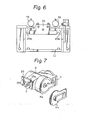
- the side cover 5b of the wrist base 5 is removed to expose the shaft 6a as shown in Fig. 7 for the reference position determining work.
- a pair of the remaining dial gauges 18 and 19 are used for determining the reference positions of the wrist front section 7 with respect to the a directions and a directions.
- the respective reference values of the dial gauges 18 and 19 are set previously by using the master block 20 as shown in Fig. 8.
- a reference position determining jig 23 having two datum surfaces 23a and 23b is attached to the wrist front section 7 as shown in Fig. 7.
- the datum surfaces 23a and 23b of the jig 23 attached to the wrist front section 7 is brought into contact with the plungers of the dial gauges 18 and 19, and then the wrist front section 7 is moved together with the wrist intermediate section 6 for adjustment in the ⁇ directions so that the indications on the dial gauges 18 and 19 coincide with the corresponding reference values.
- the reference position with respect to the ⁇ directions is determined.
- the wrist front section 7 is turned in a directions for adjustment so that the respective indications on the dial gauges 18 and 19 coincide with each other.
- the reference position with respect to a directions is determined.
- the jig 23 can be attached to the wrist front section 7 by using holes formed in the wrist front section 7 for attaching a robot hand thereto.
- the reference positions of the output end of the six-axis articulated robot are determined highly accurately by adjusting the output end so that the indications on the six dial gauges mounted on the jig body 11 for setting the respective reference positions of the axes coincide with the corresponding reference values.
- the reference positions of the axes are given and taught to an NC unit with the robot kept in the existing state, and then the device for determining the reference positions can be removed from the fixed basel.
- the device for determining the reference positions of the present invention is attached again to the fixed base 1 to determine the reference positions of the output end of the robot. That is, once the reference positions of the output end of the robot are determined and the robot and the program stored in the NC unit are matched, the robot can be controlled again by the same program.
- the fixed base of the new robot is erected on the floor at the reference position, then the device for determining the reference positions of the present invention is attached to the fixed base, and then the reference positions of the output end of the robot are determined in the same procedure as mentioned above, and thereby the two individual robots can be matched to each other. Therefore, the same program applies to the new robot.
- the present invention is not limited to the mode of the preferred embodiment, but may be applied to determining i the reference positions of articulated robots other than the six-axis articulated robot and robots capable of traveling linearly, on the basis of the spirit of the present invention, in which measuring instruments are disposed at the predetermined reference positions on the jig body in correspondence to the degrees of freedom of the output end of the objective robot and the reference position of each axis of the output is determined by the measuring instruments accordingly.
- the measuring instruments may be of any suitable type other than dial gauges.
- the present invention enables the reference positions of the output end of an industrial robot with respect to-the fixed base of the same to be determined by the use of a single jig.
- the present invention provides a method and a device for determining the reference positions of an industrial robot simply and highly accurately.
Landscapes
- Engineering & Computer Science (AREA)
- Robotics (AREA)
- Mechanical Engineering (AREA)
- Manipulator (AREA)
Applications Claiming Priority (2)
| Application Number | Priority Date | Filing Date | Title |
|---|---|---|---|
| JP58127734A JPS6020878A (ja) | 1983-07-15 | 1983-07-15 | 工業用ロボットの基準位置決め装置 |
| JP127734/83 | 1983-07-15 |
Publications (3)
| Publication Number | Publication Date |
|---|---|
| EP0149682A1 true EP0149682A1 (de) | 1985-07-31 |
| EP0149682A4 EP0149682A4 (de) | 1987-03-03 |
| EP0149682B1 EP0149682B1 (de) | 1991-09-25 |
Family
ID=14967360
Family Applications (1)
| Application Number | Title | Priority Date | Filing Date |
|---|---|---|---|
| EP84902818A Expired EP0149682B1 (de) | 1983-07-15 | 1984-07-16 | Verfahren zur bestimmung der referenzortung eines industriellen roboters |
Country Status (5)
| Country | Link |
|---|---|
| US (1) | US4702665A (de) |
| EP (1) | EP0149682B1 (de) |
| JP (1) | JPS6020878A (de) |
| DE (1) | DE3485121D1 (de) |
| WO (1) | WO1985000548A1 (de) |
Cited By (4)
| Publication number | Priority date | Publication date | Assignee | Title |
|---|---|---|---|---|
| EP0223862A4 (de) * | 1985-05-31 | 1987-07-16 | Fanuc Ltd | Vorrichtung zum einstellen eines roboters in eine referenzlage. |
| DE29909047U1 (de) * | 1999-05-22 | 2000-11-23 | KUKA Schweissanlagen GmbH, 86165 Augsburg | Positioniervorrichtung für Werkstückträger oder Werkstücke |
| US10828781B2 (en) | 2017-11-24 | 2020-11-10 | Fanuc Corporation | Calibration system and calibration method for horizontal articulated robot |
| US12390932B2 (en) | 2020-01-27 | 2025-08-19 | Fanuc Corporation | Robot calibration device |
Families Citing this family (14)
| Publication number | Priority date | Publication date | Assignee | Title |
|---|---|---|---|---|
| JPS62140783A (ja) * | 1985-12-12 | 1987-06-24 | フアナツク株式会社 | 産業用ロボツトのキヤリブレ−シヨン装置 |
| JPS62297082A (ja) * | 1986-06-16 | 1987-12-24 | フアナツク株式会社 | 産業用ロボツトの基準位置決め装置の取付構造 |
| JPS63180492A (ja) * | 1987-01-21 | 1988-07-25 | 三菱電機株式会社 | 産業用ロボツト装置 |
| JPH08379B2 (ja) * | 1987-06-19 | 1996-01-10 | 富士通株式会社 | ロボットの座標補正値測定治具 |
| JPH01121196A (ja) * | 1987-11-04 | 1989-05-12 | Fanuc Ltd | 産業用ロボットの基準姿勢較正用治具 |
| DE3822597A1 (de) * | 1988-07-04 | 1990-01-11 | Siemens Ag | Justiervorrichtung und verfahren zum justieren eines roboterarms zum einsatz in automatisierten produktionsbereichen insbesondere in der halbleitertechnik |
| US5231803A (en) * | 1992-04-13 | 1993-08-03 | Minnesota Mining And Manufacturing Company | Automated random orbital abrading method |
| JPH06210586A (ja) * | 1993-01-13 | 1994-08-02 | Fanuc Ltd | 各軸基準位置設定手段を備えた産業用ロボット |
| US5535306A (en) * | 1993-01-28 | 1996-07-09 | Applied Materials Inc. | Self-calibration system for robot mechanisms |
| TW493799U (en) * | 2000-12-15 | 2002-07-01 | Mosel Vitelic Inc | Teaching tool for a robot arm for wafer reaction ovens |
| US20030202865A1 (en) * | 2002-04-25 | 2003-10-30 | Applied Materials, Inc. | Substrate transfer apparatus |
| WO2007061603A2 (en) * | 2005-11-21 | 2007-05-31 | Applied Materials, Inc. | Methods and apparatus for transferring substrates during electronic device manufacturing |
| CN105690423A (zh) * | 2014-11-11 | 2016-06-22 | 沈阳新松机器人自动化股份有限公司 | 机器人零位标定装置及方法 |
| US12415276B2 (en) * | 2021-10-13 | 2025-09-16 | Fanuc Corporation | Positioning jig |
Family Cites Families (10)
| Publication number | Priority date | Publication date | Assignee | Title |
|---|---|---|---|---|
| US3336676A (en) * | 1965-07-20 | 1967-08-22 | Standard Gage Co Inc | Reference master for dial bore gages |
| US3496758A (en) * | 1968-01-31 | 1970-02-24 | Joseph Sunnen | Bore gage setting fixture |
| JPS505428B1 (de) * | 1969-10-24 | 1975-03-04 | ||
| JPS5224735B2 (de) * | 1971-12-22 | 1977-07-02 | ||
| JPS51141165A (en) * | 1975-05-29 | 1976-12-04 | Toshiba Corp | Reference position adjusting system for industrial robot |
| GB1603673A (en) * | 1978-05-30 | 1981-11-25 | Holbrook T | Bore gauge calibration method and apparatus |
| US4362977A (en) * | 1980-06-30 | 1982-12-07 | International Business Machines Corporation | Method and apparatus for calibrating a robot to compensate for inaccuracy of the robot |
| US4406069A (en) * | 1981-02-09 | 1983-09-27 | Clement Michael H | Perpendicularity indicator for machine tool and method of operation |
| US4372721A (en) * | 1981-05-18 | 1983-02-08 | Nordson Corporation | Apparatus for calibrating link position transducers of a teaching robot and a work robot |
| US4481592A (en) * | 1982-03-05 | 1984-11-06 | Texas Instruments Incorporated | Calibration system for a programmable manipulator |
-
1983
- 1983-07-15 JP JP58127734A patent/JPS6020878A/ja active Granted
-
1984
- 1984-07-16 DE DE8484902818T patent/DE3485121D1/de not_active Expired - Lifetime
- 1984-07-16 EP EP84902818A patent/EP0149682B1/de not_active Expired
- 1984-07-16 US US06/711,919 patent/US4702665A/en not_active Expired - Lifetime
- 1984-07-16 WO PCT/JP1984/000365 patent/WO1985000548A1/ja not_active Ceased
Cited By (4)
| Publication number | Priority date | Publication date | Assignee | Title |
|---|---|---|---|---|
| EP0223862A4 (de) * | 1985-05-31 | 1987-07-16 | Fanuc Ltd | Vorrichtung zum einstellen eines roboters in eine referenzlage. |
| DE29909047U1 (de) * | 1999-05-22 | 2000-11-23 | KUKA Schweissanlagen GmbH, 86165 Augsburg | Positioniervorrichtung für Werkstückträger oder Werkstücke |
| US10828781B2 (en) | 2017-11-24 | 2020-11-10 | Fanuc Corporation | Calibration system and calibration method for horizontal articulated robot |
| US12390932B2 (en) | 2020-01-27 | 2025-08-19 | Fanuc Corporation | Robot calibration device |
Also Published As
| Publication number | Publication date |
|---|---|
| EP0149682B1 (de) | 1991-09-25 |
| JPH0445311B2 (de) | 1992-07-24 |
| DE3485121D1 (de) | 1991-10-31 |
| WO1985000548A1 (fr) | 1985-02-14 |
| JPS6020878A (ja) | 1985-02-02 |
| US4702665A (en) | 1987-10-27 |
| EP0149682A4 (de) | 1987-03-03 |
Similar Documents
| Publication | Publication Date | Title |
|---|---|---|
| US4702665A (en) | Method and device for determining the reference positions of an industrial robot | |
| US6317699B1 (en) | Device and method for calibrating a robot | |
| US7040136B2 (en) | Apparatus and a method for calibration of an industrial robot | |
| US5239855A (en) | Positional calibration of robotic arm joints relative to the gravity vector | |
| USRE45391E1 (en) | Method and an apparatus for performing a program controlled process on a component | |
| JP3326175B2 (ja) | 産業用ロボットの運動軸の較正方法及び装置 | |
| JPWO1998032571A1 (ja) | ロボットのキャリブレーション装置および方法 | |
| JPH0126833B2 (de) | ||
| US5418890A (en) | Arm origin calibrating method for an articulated robot | |
| JPH0429515B2 (de) | ||
| EP0734816B1 (de) | Verfahren zum bestimmen von bezugspositionen eines industrieroboters | |
| US4851905A (en) | Vision target fixture construction | |
| US5570609A (en) | Industrial robot provided with means for setting reference positions for respective axes | |
| JPH05111886A (ja) | ロボツトマニピユレータのキヤリブレーシヨン点教示方法およびキヤリブレーシヨン作業方法 | |
| JP2773917B2 (ja) | ベンディング装置のワーク位置決め装置 | |
| JPH1185234A (ja) | 自動工具交換装置の教示点の位置補正装置とその方法 | |
| JP2002144034A (ja) | ロボットにおける作業具の基準位置チェック装置 | |
| JPH0446714B2 (de) | ||
| JPH05329786A (ja) | 産業用ロボット装置 | |
| KR100214675B1 (ko) | 산업용 로봇의 기준 자세 및 위치 교정 장치 및 그 방법 | |
| JP2538287B2 (ja) | 水平関節型ロボットの原点調整方式 | |
| JPH05337856A (ja) | 産業用多関節ロボットのマスタリング装置 | |
| JP2599496B2 (ja) | 産業用走行ロボットの基準位置決め方法と装置 | |
| JPH0446717B2 (de) | ||
| JP3315902B2 (ja) | オフラインティーチングにおけるツール先端点の決定方法及び決定用治具 |
Legal Events
| Date | Code | Title | Description |
|---|---|---|---|
| PUAI | Public reference made under article 153(3) epc to a published international application that has entered the european phase |
Free format text: ORIGINAL CODE: 0009012 |
|
| 17P | Request for examination filed |
Effective date: 19850328 |
|
| AK | Designated contracting states |
Designated state(s): DE FR GB |
|
| A4 | Supplementary search report drawn up and despatched |
Effective date: 19870303 |
|
| 17Q | First examination report despatched |
Effective date: 19880823 |
|
| GRAA | (expected) grant |
Free format text: ORIGINAL CODE: 0009210 |
|
| AK | Designated contracting states |
Kind code of ref document: B1 Designated state(s): DE FR GB |
|
| ET | Fr: translation filed | ||
| REF | Corresponds to: |
Ref document number: 3485121 Country of ref document: DE Date of ref document: 19911031 |
|
| PLBE | No opposition filed within time limit |
Free format text: ORIGINAL CODE: 0009261 |
|
| STAA | Information on the status of an ep patent application or granted ep patent |
Free format text: STATUS: NO OPPOSITION FILED WITHIN TIME LIMIT |
|
| 26N | No opposition filed | ||
| PGFP | Annual fee paid to national office [announced via postgrant information from national office to epo] |
Ref country code: GB Payment date: 19980707 Year of fee payment: 15 |
|
| PGFP | Annual fee paid to national office [announced via postgrant information from national office to epo] |
Ref country code: FR Payment date: 19980709 Year of fee payment: 15 |
|
| PGFP | Annual fee paid to national office [announced via postgrant information from national office to epo] |
Ref country code: DE Payment date: 19980724 Year of fee payment: 15 |
|
| PG25 | Lapsed in a contracting state [announced via postgrant information from national office to epo] |
Ref country code: GB Free format text: LAPSE BECAUSE OF NON-PAYMENT OF DUE FEES Effective date: 19990716 |
|
| PG25 | Lapsed in a contracting state [announced via postgrant information from national office to epo] |
Ref country code: FR Free format text: THE PATENT HAS BEEN ANNULLED BY A DECISION OF A NATIONAL AUTHORITY Effective date: 19990731 |
|
| GBPC | Gb: european patent ceased through non-payment of renewal fee |
Effective date: 19990716 |
|
| PG25 | Lapsed in a contracting state [announced via postgrant information from national office to epo] |
Ref country code: DE Free format text: LAPSE BECAUSE OF NON-PAYMENT OF DUE FEES Effective date: 20000503 |
|
| REG | Reference to a national code |
Ref country code: FR Ref legal event code: ST |