EP0136542B1 - Procédé pour commander l'impression en couleurs, utilisant des surfaces de contrôle en demi tons - Google Patents
Procédé pour commander l'impression en couleurs, utilisant des surfaces de contrôle en demi tons Download PDFInfo
- Publication number
- EP0136542B1 EP0136542B1 EP84110310A EP84110310A EP0136542B1 EP 0136542 B1 EP0136542 B1 EP 0136542B1 EP 84110310 A EP84110310 A EP 84110310A EP 84110310 A EP84110310 A EP 84110310A EP 0136542 B1 EP0136542 B1 EP 0136542B1
- Authority
- EP
- European Patent Office
- Prior art keywords
- halftone
- densities
- color
- control
- magenta
- Prior art date
- Legal status (The legal status is an assumption and is not a legal conclusion. Google has not performed a legal analysis and makes no representation as to the accuracy of the status listed.)
- Expired
Links
- 238000007639 printing Methods 0.000 title claims description 31
- 238000000034 method Methods 0.000 claims description 56
- 239000007787 solid Substances 0.000 claims description 31
- 238000005259 measurement Methods 0.000 claims description 14
- 230000003287 optical effect Effects 0.000 claims description 9
- 238000011088 calibration curve Methods 0.000 claims description 6
- 238000011156 evaluation Methods 0.000 claims description 4
- 239000000976 ink Substances 0.000 description 30
- 239000003086 colorant Substances 0.000 description 11
- 239000000470 constituent Substances 0.000 description 6
- 239000000758 substrate Substances 0.000 description 5
- 230000000007 visual effect Effects 0.000 description 5
- 230000000295 complement effect Effects 0.000 description 3
- 238000001739 density measurement Methods 0.000 description 3
- 230000006870 function Effects 0.000 description 3
- 239000011159 matrix material Substances 0.000 description 3
- 230000000694 effects Effects 0.000 description 2
- 239000000463 material Substances 0.000 description 2
- 230000007935 neutral effect Effects 0.000 description 2
- 230000003595 spectral effect Effects 0.000 description 2
- 239000002699 waste material Substances 0.000 description 2
- 239000000654 additive Substances 0.000 description 1
- 230000000996 additive effect Effects 0.000 description 1
- 238000004458 analytical method Methods 0.000 description 1
- 238000000149 argon plasma sintering Methods 0.000 description 1
- 238000003491 array Methods 0.000 description 1
- 230000001419 dependent effect Effects 0.000 description 1
- 238000013461 design Methods 0.000 description 1
- 238000007647 flexography Methods 0.000 description 1
- 230000010354 integration Effects 0.000 description 1
- 238000001459 lithography Methods 0.000 description 1
- 238000013178 mathematical model Methods 0.000 description 1
- 238000012544 monitoring process Methods 0.000 description 1
- 230000035515 penetration Effects 0.000 description 1
- 238000003908 quality control method Methods 0.000 description 1
- 238000002310 reflectometry Methods 0.000 description 1
- 238000011160 research Methods 0.000 description 1
- 238000006467 substitution reaction Methods 0.000 description 1
- XLYOFNOQVPJJNP-UHFFFAOYSA-N water Substances O XLYOFNOQVPJJNP-UHFFFAOYSA-N 0.000 description 1
Images



Classifications
-
- B—PERFORMING OPERATIONS; TRANSPORTING
- B41—PRINTING; LINING MACHINES; TYPEWRITERS; STAMPS
- B41F—PRINTING MACHINES OR PRESSES
- B41F33/00—Indicating, counting, warning, control or safety devices
- B41F33/0036—Devices for scanning or checking the printed matter for quality control
-
- G—PHYSICS
- G01—MEASURING; TESTING
- G01J—MEASUREMENT OF INTENSITY, VELOCITY, SPECTRAL CONTENT, POLARISATION, PHASE OR PULSE CHARACTERISTICS OF INFRARED, VISIBLE OR ULTRAVIOLET LIGHT; COLORIMETRY; RADIATION PYROMETRY
- G01J3/00—Spectrometry; Spectrophotometry; Monochromators; Measuring colours
- G01J3/46—Measurement of colour; Colour measuring devices, e.g. colorimeters
-
- G—PHYSICS
- G01—MEASURING; TESTING
- G01J—MEASUREMENT OF INTENSITY, VELOCITY, SPECTRAL CONTENT, POLARISATION, PHASE OR PULSE CHARACTERISTICS OF INFRARED, VISIBLE OR ULTRAVIOLET LIGHT; COLORIMETRY; RADIATION PYROMETRY
- G01J3/00—Spectrometry; Spectrophotometry; Monochromators; Measuring colours
- G01J3/46—Measurement of colour; Colour measuring devices, e.g. colorimeters
- G01J3/50—Measurement of colour; Colour measuring devices, e.g. colorimeters using electric radiation detectors
- G01J3/51—Measurement of colour; Colour measuring devices, e.g. colorimeters using electric radiation detectors using colour filters
Definitions
- This invention relates to a method for controlling multicolor printing processes, including lithography, gravure, letterpress and flexography, whereby predetermined areas on the printed material are measured by a densitometer, either manually, or automatically on the printing press. The results of these measurements are used to control various parameters on the printing press in order to maintain an acceptable level of quality in the printed colors.
- Multi-color printing processes most often combine four inks, called process inks, in order to achieve the final printed product. These colors, usually cyan, magenta, yellow and black, are printed sequentially on the same area of the substrate, and interact to produce a wide gamut of colors. Most printed images are produced with halftone screens, yielding images that are arrays of small dots of varying sizes. Both, the amount of ink present in the dots, and the dot sizes, are important in achieving the proper printed color.
- a densitometer is an optical instrument used to measure the lightness or darkness of an image. Its numerical output, called optical density, is based in the logarithm of the optical reflectance of the image, and correlates well with visually perceived lightness or darkness. The logarithmic scale, however, is not necessary for the control of printing, and a reflectance measuring instrument based on linear scaling could be used for the same purpose.
- the densitometer utilizes color filters or other means for isolating spectral regions that are complementary to the colors of the process inks in density.
- Instruments known as reflectometers or spectrophotometers, when used for the same purpose, are equivalent to a densitometer.
- Patents describing densitometers that provide density readout to the press operator are, e.g., US 2,968,988 and US 4,210,078.
- Patents that suggest the use of density measurements for automatic inking control are, e.g., US 3,756,725, 3,835,777, 4,003,660 and 4,200,932. None of these patents describe the exclusive use of two different three-color halftone control targets for the instrumental control of multi-color printing.
- control targets often called color bars. These are usually printed in a waste area of the sheet and contain a variety of targets for each color. Control targets consist of patches of solid and halftone printing, for each ink individually, as well as in combination with different inks. Provided that changes within the control targets are representative of those occurring within the image, measurements of the control targets can be used as an objective means of monitoring and controlling the color of the printing. Control targets are often disposed at various locations across the printed image, and so a densitometer needs to be positioned at these various locations in order to measure their optical densities. One or more densitometers can be sequentially positioned at these multiple locations, or mounted at fixed positions of a limited number of lateral positions across the width of the press need to be accessed.
- tone reproduction which implies control of dot size
- solid density The parameters which are essential in this context are those which directly affect the amount of ink layed down on the substrate, and the dot area produced together with the relative magnitude of each of these parameters when more than one color is printed.
- the amount of ink applied to the substrate can be monitored by measuring, with a densitometer, the optical density of a solid color bar. The measurement can be made automatically on the press, or manually off the press. Dot area is determined by first measuring the density of a halftone color bar and a nearby solid color bar and then calculating dot area via an equation such as the Yule-Nielsen equation which is disclosed in Yule, J. A. C. and Nielsen, W. J. "The Penetration of Light into Paper and its Effect on Halftone Reproduction", TAGA Proceedings, 1951, pp. 65-76. In the Yule-Nielsen equation, D h is halftone density, O s is solid density and n is a constant factor that accounts for the light scattering properties of the substrate.
- the dot area "a” has a value between 0 and 1.
- the printed dot area is influenced by a multitude of printing parameters, including the pressure between the printing plate and the blanket cylinder, the thickness of the ink film, the ink/water balance and various mechanical properties of the press. Increase in dot area, known as dot gain, must be continually monitored during a run, since excessive dot gain will influence the tone reproduction and color of the printed image.
- color bars are not usually desired in the final printed product. Sometimes, the color bars are printed in a region that will later be trimmed so that they can be used for control of printing, and then discarded. In some instances, the color bars can be hidden, as in the folds of a package, or in the binding of a magazine. When color bars cannot be trimmed or hidden, they are usually not printed. In such cases, the use of instrumentation for control is abandoned.
- Gray balance is the ability of the three process color inks to be combined in the proper proportions to form a visual neutral or near-neutral color.
- the gray balance target is designed to visual judgement. A significant change in the hue indicates a change in inking or dot gain in one of the. process inks.
- Gray balance targets can be camouflaged by integration into printed borders or logos.
- gray balance control targets cannot be printed with enough accuracy to assure that they remain of consistent hue.
- Gray balance targets are extremely sensitive to changes in inking and dot gain, and while they would, therefore, be ideal for the control of some printing processes, they may be overly sensitive in other applications where a change in hue would be objectionable.
- three-color halftone images with desired hues could be used, and similarly hidden in borders or logos. Even selected regions of the printed image could be used, eliminating the need for the use of control targets.
- the method of the invention for determining a multi-color printing the solid density and the amount of dot gain of each process color image is characterized by the steps of printing two different three-color halftone control areas, one light and one dark, each consisting of overprinted cyan, magenta and yellow halftones; measuring with a densitometer the blue, green and red optical densities of both control areas; calculating the densities of the halftones of cyan, magenta and yellow ink from the blue, green and red densities of the first control area; calculating the densities of the halftones of cyan, magenta and yellow ink from the blue; green and red densities of the second control area; and calculating the solid densities and dot gains of the cyan, magenta and yellow images from the densities of the first and second halftones of cyan, magenta and yellow according to with the subscripts "1" and "2" referring to the first and second halftones respectively, for each process color; and dot gain by evaluating the
- the invention comprises the method for determining dot gain and solid density, based in the use of two different three-color halftone control targets, and without the use of single-color solid or halftone color bars. These control targets or image regions can be referred to as "control areas".
- control areas These control targets or image regions can be referred to as "control areas".
- control areas In the common case, when halftone and solid color bars are printed in each of the process colors, solid density is found directly, and dot area is found via the Yule-Nielsen equation.
- the invention provides equations for determining yellow, magenta and cyan dot gain and solid density based on measurements of the optical density of two different three-color halftone control areas, rather than three solid targets and three halftone targets.
- the method of the present invention for calculating dot gain in single color printing from measurements of the densities of a first and second halftone is characterized in that the dot area of the first, dark halftone does not exceed 75% and the dot area of the second, light halftone does not exceed 40%: and by the steps of evaluating the equation where R L is the reflectance of the second, light halftone and R D is the reflectance of the first, dark halftone; and finding the value of dot gain corresponding to said evaluation on a calibration curve.
- the invention makes use of three-color halftone control targets or image regions, in which the relative dot areas of the cyan, magenta and yellow images are properly chosen to give the desired hues.
- the invention requires the use of two three-color halftone control targets or image regions, or two gray balance control targets. If image regions cannot be used, a border, design or logo can be configured out of the two control targets such that its presence is acceptable in the final printed publication. There are then two steps to the method.
- No. 1 Use blue, green and red density measurements of the two control targets or image regions to determine the densities of the individual halftone patterns of cyan, magenta and yellow process inks that make up the two three-color halftone control targets or image regions.
- step No. 1 The methods used in step No. 1 are not mathematically exact, but are based on approximation that have been empirically determined to be sufficient to make the method of practical use.
- the preferred method of step No. 2 is a mathematically exact solution, based in a theoretical model of dot gain.
- step No. 1 a mathematically correct analysis does exist for the special case of three overprinted solid colors. It is assumed that there is 100% trapping (i.e., each ink prints on the other inks as it would print on paper) and the Beer-Lambert law is obeyed (i.e., the densities are additive). Under these assumptions, the following three equations can be written for the blue, green and red densities of the overprint: where
- bracketed ratios are constants that depend on the spectral shapes of the ink reflectivities.
- the equations can then be rewritten in the following form:
- the method outlined above which is mathematically correct for solid overprints with 100% trapping, can be applied to the pair of three-color halftone control targets or image regions.
- the a, j coefficient in equations (5), (6) and (7) which are ratios of densities, are determined empirically by measuring the single color halftones that make up the three-color halftone control targets or image regions, with a densitometer. This is a calibration step that only need be done once with a given set of inks and corresponding substrate, and involves printing the separate color halftones that constitute the two different control targets or image regions.
- step No. 2 it is assumed that step No. 1 is complete, and that given the blue, green and red densities of the first and second three-color halftone control targets or image regions, equivalent densities of the halftones for the cyan, magenta and yellow inks have been calculated. Considering each process ink separately, then the densities of the first and second halftones, D 1 and D 2 , are given.
- the method depends on a mathematical model that describes dot gain as a function of dot area.
- One model that has shown good correlation with empirical measurements is the GRL model which is disclosed in J. A. S. Viggiano, "The GRL Dot Gain Model", TAGA Proceedings, 1983.
- Equations (12) and (13) can be solved simultaneously for the two unknowns 6 and Rg, given by
- equations (14) and (15) provide the pressman with the information needed to take corrective action.
- step No. 2 proceeds as follows.
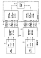
- the present invention will be described when two different gray balance control targets are used.
- the light gray balance control target 10 is measured through the blue, red and green filters of densitometer 12.
- the same three density readings are taken for the dark gray balance target 13 by densitometer 12.
- a set of simultaneous equations is solved in a suitably programmed computer 15 for the densities of the cyan, magenta and yellow halftones that make up the gray balance target.
- These halftone densities are then analyzed in pairs, one light and one dark halftone for each process color, in order to find the dot gain 6 for a 50% dot area target, and the equivalent solid density.
- This information is then displayed to the pressman on a display 16 such as a CRT.
- step 1 the procedure is shown for calibration of step 1, in which the densities of the cyan, magenta and yellow halftones are calculated from measurements of the gray balance targets 10, 13 (Fig. 1).
- the next step is to measure the blue, green and red densities of the two sets of three halftones 17, 18 with densitometer 19.
- the densities of the halftones 17, 18 are used to calculate the a lj coefficients of the gray balance targets 10, 13 to calculate the densities of the individual constituent halftones, according to equations (8), (9) and (10) described hereinbefore.
- the coefficients are calculated in computer 15 and stored in memory 22 for future use.
- Figure 3 shows a flow chart for the calibration required for the alternate empirical solution of step No. 2.
- the two gray balance targets 10, 13 along with the three targets of the dark constituent halftones 24, as well as cyan, magenta and yellow solids 23 are printed.
- This group of eight targets 10, 13, 24, 23 should be printed under a variety of press conditions in order to generate variations in dot gain that are representative of the variations that will be encountered under normal operation.
- the two gray balance targets 10, 13 should be measured with densitometer 12 for blue, green and red densities.
- the densities are converted in computer 15 to reflectances, and the expression in equation (16) is calculated in computer 15 separately for the blue, green and red channels. Then the dot gain of the dark halftones should be found by measuring the dark halftones and solids with densitometer 25 and using the Yule-Nielsen equation. Calibration then involves the plotting of a calibration curve of the expression in equation (16) as a function of dot gain, separately for the blue, green and red ratios. These curves are then used in the solution of step No. 2, whereby the expression derived from measurement of the light and dark halftones would correspond to a unique value of dot gain.
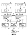
- the present invention will be described when two different three-color halftone control areas are used.
- the first control area 110 is measured through the blue, green and red filters of a densitometer 112.
- the same three density readings are taken for the second control area 113 by densitometer 112.
- a set of simultaneous equations is solved in suitably programmed computer 115 for the densities of cyan, magenta and yellow halftones that make up the three-color halftone control areas.
- These halftone densities are then analyzed in pairs, for each process color, in order to find the dot gain 6 for a 50% dot area target, and the equivalent solid density. This information is then displayed to the pressman on a display 116 such as a CRT.
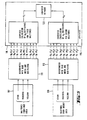
- step No. 1 the procedure is shown for calibration of step No. 1, in which the densities of the cyan, magenta and yellow halftones are calculated from measurements of the three-color halftone control areas 110, 113 (Fig. 4). We need to print the constituent cyan, magenta and yellow halftones that are used for the control areas 110, 113.
- the next step is to measure the blue, green and red densities of the two sets of three halftones 117, 118 with densitometer 119.
- the densities of the halftones 117, 118 are used to calculate the a, j coefficients, which are required for use in conjunction with the densities of the control areas 110, 113 to calculate the densities of the individual constituent halftones, according to equations (8), (9) and (10) described hereinbefore.
- the coefficients are calculated in computer 115 and stored in memory 122 for future use.
- Figure 6 shows a flow chart for the calibration required for the alternate empirical solution of step No. 2.
- the two control areas 110, 113, along with the three targets of the second constituent halftones 124, as well as cyan, magenta and yellow solids 123 are printed.
- This group of eight areas 110, 113, 124 and 123 should be printed under a variety of press conditions to generate variations in dot gain that are representative of the variations that will be encountered under normal operation.
- the two control areas 110, 113 should be measured with densitometer 112 for blue, green and red densities.
- the densities are converted in computer 115 separately for the blue, green and red channels. Then the dot gain of the second halftones should be found by measuring the second halftones and solids with densitometer 125 and using the Yule-Nielsen equation.
- Calibration then involves the plotting of a calibration curve of the expression in equation (16) as a function of dot gain, separately for the blue, green and red ratios. These curves are then used in the solution of step No. 2, whereby the expression derived from measurement of the first and second halftones would correspond to a unique value of dot gain.
Landscapes
- Physics & Mathematics (AREA)
- Spectroscopy & Molecular Physics (AREA)
- Engineering & Computer Science (AREA)
- Quality & Reliability (AREA)
- General Physics & Mathematics (AREA)
- Spectrometry And Color Measurement (AREA)
- Inking, Control Or Cleaning Of Printing Machines (AREA)
Claims (11)


Applications Claiming Priority (4)
| Application Number | Priority Date | Filing Date | Title |
|---|---|---|---|
| US53392583A | 1983-09-20 | 1983-09-20 | |
| US533925 | 1983-09-20 | ||
| US643243 | 1984-08-24 | ||
| US06/643,243 US4706206A (en) | 1983-09-20 | 1984-08-24 | Color printing control using halftone control areas |
Publications (3)
| Publication Number | Publication Date |
|---|---|
| EP0136542A2 EP0136542A2 (fr) | 1985-04-10 |
| EP0136542A3 EP0136542A3 (en) | 1987-07-22 |
| EP0136542B1 true EP0136542B1 (fr) | 1990-08-08 |
Family
ID=27064305
Family Applications (1)
| Application Number | Title | Priority Date | Filing Date |
|---|---|---|---|
| EP84110310A Expired EP0136542B1 (fr) | 1983-09-20 | 1984-08-30 | Procédé pour commander l'impression en couleurs, utilisant des surfaces de contrôle en demi tons |
Country Status (3)
| Country | Link |
|---|---|
| US (1) | US4706206A (fr) |
| EP (1) | EP0136542B1 (fr) |
| DE (1) | DE3482925D1 (fr) |
Cited By (2)
| Publication number | Priority date | Publication date | Assignee | Title |
|---|---|---|---|---|
| DE4402828A1 (de) * | 1994-01-31 | 1995-08-10 | Wifag Maschf | Color-Management im Rollenoffset-Auflagendruck |
| DE4413735A1 (de) * | 1994-04-20 | 1995-10-26 | Heidelberger Druckmasch Ag | Verfahren zum Steuern oder Regeln der Rasterpunktgröße beim Drucken auf einen Bedruckstoff |
Families Citing this family (29)
| Publication number | Priority date | Publication date | Assignee | Title |
|---|---|---|---|---|
| US5182721A (en) * | 1985-12-10 | 1993-01-26 | Heidelberger Druckmaschinen Aktiengesellschaft | Process and apparatus for controlling the inking process in a printing machine |
| FI861578A0 (fi) * | 1986-04-14 | 1986-04-14 | Valtion Teknillinen | Foerfarande foer kvalitetskontroll av tryckning. |
| JPS6328649A (ja) * | 1986-07-22 | 1988-02-06 | Dainippon Screen Mfg Co Ltd | オフセツト校正機におけるドツトゲイン量の制御方法 |
| DE3626423A1 (de) * | 1986-08-05 | 1988-02-11 | Deutsche Forsch Druck Reprod | Verfahren und vorrichtung zur beeinflussung der farblichen erscheinung einer farbflaeche bei einem druckvorgang |
| US4947348A (en) * | 1987-03-25 | 1990-08-07 | Kollmorgen Corporation | Densitometer method and system for identifying and analyzing printed targets |
| US4967379A (en) * | 1987-12-16 | 1990-10-30 | Gretag Aktiengesellschaft | Process for the ink control or regulation of a printing machine by comparing desired color to obtainable color data |
| DE58901780D1 (de) * | 1988-01-14 | 1992-08-13 | Gretag Ag | Verfahren und vorrichtung zur farbregelung einer druckmaschine. |
| DE3812099C2 (de) * | 1988-04-12 | 1995-01-26 | Heidelberger Druckmasch Ag | Verfahren zur Farbsteuerung einer Offsetdruckmaschine |
| US4959790A (en) * | 1988-06-28 | 1990-09-25 | F & S Corporation Of Columbus, Georgia | Apparatus and method for producing color corrected reproduction of colored original images |
| DE3830731A1 (de) * | 1988-09-09 | 1990-03-22 | Heidelberger Druckmasch Ag | Vorrichtung zur farbmessung |
| DE3903981C2 (de) * | 1989-02-10 | 1998-04-09 | Heidelberger Druckmasch Ag | Verfahren zur Regelung der Farbfüllung bei einer Druckmaschine |
| DE59003421D1 (de) * | 1989-07-14 | 1993-12-16 | Gretag Ag | Verfahren zur Bestimmung der Farbmasszahldifferenzen zwischen zwei mit hilfe einer Druckmaschine gedruckten Rasterfeldern sowie Verfahren zur Farbsteuerung oder Farbregelung des Druckes einer Druckmaschine. |
| US5187594A (en) * | 1990-02-09 | 1993-02-16 | Graphic Edge, Inc. | Method of creating and applying half tone screen patterns |
| EP0546112B1 (fr) * | 1990-08-29 | 1996-04-03 | E.I. Du Pont De Nemours And Company | Procede de creation de reproductions en demi-tons multicolores a partir d'originaux monochromes a ton continu |
| DE4209165A1 (de) * | 1991-03-21 | 1992-09-24 | Wifag Maschf | Verfahren zur einstellung der rasterpunktgroessen fuer eine offset-rotationsdruckmaschine |
| US5317425A (en) * | 1992-02-10 | 1994-05-31 | Eastman Kodak Company | Technique for use in conjunction with an imaging system for providing an appearance match between two images and for calibrating the system thereto |
| US5357448A (en) * | 1993-02-02 | 1994-10-18 | Quad/Tech, Inc. | Method and apparatus for controlling the printing of an image having a plurality of printed colors |
| DE4431270C2 (de) * | 1993-10-21 | 1997-01-16 | Roland Man Druckmasch | Verfahren zur Steuerung der Farbführung einer autotypisch arbeitenden Druckmaschine |
| US5748330A (en) * | 1997-05-05 | 1998-05-05 | Xerox Corporation | Method of calibrating a digital printer using component test patches and the yule-nielsen equation |
| US6268932B1 (en) | 1998-04-23 | 2001-07-31 | Internatiaonal Business Machines Corporation | Gray scale calibration tool for setting the density of a printer |
| BR0207825A (pt) * | 2001-03-02 | 2004-04-27 | Ackley Martinez Company Dba Mg | Sistema e método de ajuste de impressão |
| CN1537055A (zh) * | 2001-07-30 | 2004-10-13 | 阿克利・马丁内斯公司Dba Mgi工作 | 色彩管理处理系统和方法 |
| JP2004536731A (ja) | 2001-07-30 | 2004-12-09 | ジ アックレイ マルティネス カンパニー デイビーエイ エムジーアイ ステューディオ | システム混合を補償するシステムと方法 |
| JP4047068B2 (ja) * | 2002-05-21 | 2008-02-13 | 大日本スクリーン製造株式会社 | 印刷機 |
| JP2004334703A (ja) * | 2003-05-09 | 2004-11-25 | Canon Inc | 印刷制御方法及び装置 |
| US7554696B2 (en) | 2004-02-26 | 2009-06-30 | Sharp Laboratories Of America, Inc. | Dot-gain reduction method for multi-level halftoning |
| US7605959B2 (en) | 2005-01-05 | 2009-10-20 | The Ackley Martinez Company | System and method of color image transformation |
| EP1839854A1 (fr) * | 2006-03-31 | 2007-10-03 | ELTROMAT GmbH | Méthode et dispositif pour ajuster optimalement la position dans une machine d'impression rotative fléxographique |
| CN103158348B (zh) * | 2011-12-14 | 2015-11-04 | 中国科学院沈阳计算技术研究所有限公司 | 基于单片机的多路印刷卡控制系统 |
Family Cites Families (12)
| Publication number | Priority date | Publication date | Assignee | Title |
|---|---|---|---|---|
| US2968988A (en) * | 1955-03-18 | 1961-01-24 | Crosfield J F Ltd | Apparatus for indicating changes in ink |
| US3054561A (en) * | 1959-01-08 | 1962-09-18 | Hazeltine Research Inc | Computer for color-film analyzer |
| US3555262A (en) * | 1968-05-07 | 1971-01-12 | Dainippon Screen Mfg | Apparatus for production of color separation records |
| US3756725A (en) * | 1970-10-12 | 1973-09-04 | Harris Intertype Corp | Measurement and control of ink density |
| US3835777A (en) * | 1973-01-16 | 1974-09-17 | Harris Intertype Corp | Ink density control system |
| US4210078A (en) * | 1974-06-24 | 1980-07-01 | M.A.N.-Roland Druckmaschinen Aktiengesellschaft | Apparatus for use on printing presses to insure optimum color density and to assist in making corrective adjustment |
| US4003660A (en) * | 1975-12-03 | 1977-01-18 | Hunter Associates Laboratory, Inc. | Sensing head assembly for multi-color printing press on-line densitometer |
| DE2728738B2 (de) * | 1977-06-25 | 1979-05-10 | Roland Offsetmaschinenfabrik Faber & Schleicher Ag, 6050 Offenbach | Eulrichtung zur Kontrolle und Regelung der Farbgebung an Druckmaschinen |
| DE2853509C2 (de) * | 1978-12-12 | 1983-02-03 | Dr.-Ing. Rudolf Hell Gmbh, 2300 Kiel | Einrichtung zur Herstellung von Farbauszügen |
| DE2950650A1 (de) * | 1979-12-15 | 1981-06-19 | M.A.N.- Roland Druckmaschinen AG, 6050 Offenbach | Vorrichtung zur opto- elektronischen messung der flaechendeckung einer offset-druckplatte oder einer der offset-druckplattenherstellung dienenden druckvorlage |
| US4310248A (en) * | 1980-04-24 | 1982-01-12 | Meredith Nolan J | Color control system |
| DE3232577A1 (de) * | 1981-09-12 | 1983-03-31 | Dainippon Screen Manufacturing Co., Ltd., Kyoto | Verfahren und vorrichtung zur farbkonzentrationsmessung in druckerzeugnissen |
-
1984
- 1984-08-24 US US06/643,243 patent/US4706206A/en not_active Expired - Fee Related
- 1984-08-30 EP EP84110310A patent/EP0136542B1/fr not_active Expired
- 1984-08-30 DE DE8484110310T patent/DE3482925D1/de not_active Expired - Lifetime
Cited By (4)
| Publication number | Priority date | Publication date | Assignee | Title |
|---|---|---|---|---|
| DE4402828A1 (de) * | 1994-01-31 | 1995-08-10 | Wifag Maschf | Color-Management im Rollenoffset-Auflagendruck |
| DE4402828C2 (de) * | 1994-01-31 | 2001-07-12 | Wifag Maschf | Messfeldgruppe und Verfahren zur Qualitätsdatenerfassung unter Verwendung der Messfeldgruppe |
| DE4413735A1 (de) * | 1994-04-20 | 1995-10-26 | Heidelberger Druckmasch Ag | Verfahren zum Steuern oder Regeln der Rasterpunktgröße beim Drucken auf einen Bedruckstoff |
| DE4413735C2 (de) * | 1994-04-20 | 2003-09-25 | Heidelberger Druckmasch Ag | Verfahren zum Steuern oder Regeln des Druckprozesses einer autotypisch arbeitenden Druckmaschine beim Drucken unter Druckpressung auf einen Bedruckstoff |
Also Published As
| Publication number | Publication date |
|---|---|
| US4706206A (en) | 1987-11-10 |
| EP0136542A3 (en) | 1987-07-22 |
| DE3482925D1 (de) | 1990-09-13 |
| EP0136542A2 (fr) | 1985-04-10 |
Similar Documents
| Publication | Publication Date | Title |
|---|---|---|
| EP0136542B1 (fr) | Procédé pour commander l'impression en couleurs, utilisant des surfaces de contrôle en demi tons | |
| CA2428040C (fr) | Procede de maitrise de la couleur spectrale | |
| JP2895404B2 (ja) | ハーフトーン階調印刷機のインキ供給制御方法 | |
| US5357448A (en) | Method and apparatus for controlling the printing of an image having a plurality of printed colors | |
| CA1216943A (fr) | Methode et dispositif d'evaluation de la qualite d'impression, et de regulation de l'apport d'encre sur machine offset | |
| US4852485A (en) | Method of operating an autotypical color offset printing machine | |
| EP1437222B1 (fr) | Procede d'impression, matiere imprimee et controleur d'impression | |
| AU2001278064A1 (en) | Spectral color control method | |
| EP1712361B1 (fr) | Dispositif de sélection des encres dans la commande de l'alimentation d'encre d'une machine d'impression | |
| EP1464493B2 (fr) | Machine à imprimer | |
| JPH01225554A (ja) | 印刷機のインク制御のための方法及び装置 | |
| EP2295256A1 (fr) | Procédé de régulation de la balance de gris neutre | |
| US20160284101A1 (en) | Method for correcting deviations of measured image data | |
| US5761327A (en) | Group of measured fields for determining color data of a printed product | |
| EP1363779B1 (fr) | Systeme et procede d'ajustement d'impression | |
| JPS61248748A (ja) | オートタイプ式作動型の多色オフセツト印刷機により均等な印刷結果を達成する方法および単色ストリツプセツト | |
| EP1323530A2 (fr) | Procédé de réglage de teinte pour une presse d'impression | |
| US6802254B2 (en) | Method and apparatus for controlling color of a printing press based upon colorimetric density differences | |
| JPS6091357A (ja) | ハーフトーン制御領域を用いるカラー印刷の制御方法 | |
| RU2278788C2 (ru) | Способ спектрального контроля цвета | |
| Gooran et al. | A novel spectral trapping model for color halftones | |
| Smith | Analysis of color variation during four-color offset lithographic press runs by monitoring changes in three-filter density values of overprint tints | |
| Lychock | Dot Area, Dot Gain, and n-Factors | |
| Meyer | The variability of a web offset newspaper press run as measured by the Eastman Kodak Company's customized color analysis target | |
| Seymour | Building a bridge from Dense City to Colorimetropolis |
Legal Events
| Date | Code | Title | Description |
|---|---|---|---|
| PUAI | Public reference made under article 153(3) epc to a published international application that has entered the european phase |
Free format text: ORIGINAL CODE: 0009012 |
|
| AK | Designated contracting states |
Designated state(s): CH DE FR GB IT LI SE |
|
| 17P | Request for examination filed |
Effective date: 19850930 |
|
| PUAL | Search report despatched |
Free format text: ORIGINAL CODE: 0009013 |
|
| AK | Designated contracting states |
Kind code of ref document: A3 Designated state(s): CH DE FR GB IT LI SE |
|
| 17Q | First examination report despatched |
Effective date: 19880919 |
|
| RAP1 | Party data changed (applicant data changed or rights of an application transferred) |
Owner name: KOLLMORGEN CORPORATION |
|
| GRAA | (expected) grant |
Free format text: ORIGINAL CODE: 0009210 |
|
| AK | Designated contracting states |
Kind code of ref document: B1 Designated state(s): CH DE FR GB IT LI SE |
|
| ITF | It: translation for a ep patent filed | ||
| ET | Fr: translation filed | ||
| ITTA | It: last paid annual fee | ||
| REF | Corresponds to: |
Ref document number: 3482925 Country of ref document: DE Date of ref document: 19900913 |
|
| PLBE | No opposition filed within time limit |
Free format text: ORIGINAL CODE: 0009261 |
|
| STAA | Information on the status of an ep patent application or granted ep patent |
Free format text: STATUS: NO OPPOSITION FILED WITHIN TIME LIMIT |
|
| 26N | No opposition filed | ||
| PGFP | Annual fee paid to national office [announced via postgrant information from national office to epo] |
Ref country code: SE Payment date: 19920721 Year of fee payment: 9 |
|
| PG25 | Lapsed in a contracting state [announced via postgrant information from national office to epo] |
Ref country code: SE Effective date: 19930831 |
|
| REG | Reference to a national code |
Ref country code: GB Ref legal event code: 732E |
|
| REG | Reference to a national code |
Ref country code: CH Ref legal event code: PUE Owner name: KOLLMORGEN INSTRUMENTS CORPORATION |
|
| REG | Reference to a national code |
Ref country code: FR Ref legal event code: TP |
|
| EUG | Se: european patent has lapsed |
Ref document number: 84110310.4 Effective date: 19940310 |
|
| REG | Reference to a national code |
Ref country code: CH Ref legal event code: PUE Owner name: KOLLMORGEN INSTRUMENTS CORPORATION TRANSFER- GRETA Ref country code: CH Ref legal event code: NV Representative=s name: ISLER & PEDRAZZINI AG |
|
| REG | Reference to a national code |
Ref country code: GB Ref legal event code: 732E |
|
| REG | Reference to a national code |
Ref country code: FR Ref legal event code: TP |
|
| PGFP | Annual fee paid to national office [announced via postgrant information from national office to epo] |
Ref country code: GB Payment date: 19980803 Year of fee payment: 15 |
|
| PGFP | Annual fee paid to national office [announced via postgrant information from national office to epo] |
Ref country code: FR Payment date: 19980813 Year of fee payment: 15 |
|
| PGFP | Annual fee paid to national office [announced via postgrant information from national office to epo] |
Ref country code: CH Payment date: 19980923 Year of fee payment: 15 |
|
| PGFP | Annual fee paid to national office [announced via postgrant information from national office to epo] |
Ref country code: DE Payment date: 19981028 Year of fee payment: 15 |
|
| PG25 | Lapsed in a contracting state [announced via postgrant information from national office to epo] |
Ref country code: GB Free format text: LAPSE BECAUSE OF NON-PAYMENT OF DUE FEES Effective date: 19990830 |
|
| PG25 | Lapsed in a contracting state [announced via postgrant information from national office to epo] |
Ref country code: LI Free format text: LAPSE BECAUSE OF NON-PAYMENT OF DUE FEES Effective date: 19990831 Ref country code: CH Free format text: LAPSE BECAUSE OF NON-PAYMENT OF DUE FEES Effective date: 19990831 |
|
| REG | Reference to a national code |
Ref country code: CH Ref legal event code: PL |
|
| GBPC | Gb: european patent ceased through non-payment of renewal fee |
Effective date: 19990830 |
|
| PG25 | Lapsed in a contracting state [announced via postgrant information from national office to epo] |
Ref country code: FR Free format text: LAPSE BECAUSE OF NON-PAYMENT OF DUE FEES Effective date: 20000428 |
|
| PG25 | Lapsed in a contracting state [announced via postgrant information from national office to epo] |
Ref country code: DE Free format text: LAPSE BECAUSE OF NON-PAYMENT OF DUE FEES Effective date: 20000601 |
|
| REG | Reference to a national code |
Ref country code: FR Ref legal event code: ST |