EP0136671A2 - Prothèse dentaire amovible et sa méthode de fabrication - Google Patents
Prothèse dentaire amovible et sa méthode de fabrication Download PDFInfo
- Publication number
- EP0136671A2 EP0136671A2 EP84111623A EP84111623A EP0136671A2 EP 0136671 A2 EP0136671 A2 EP 0136671A2 EP 84111623 A EP84111623 A EP 84111623A EP 84111623 A EP84111623 A EP 84111623A EP 0136671 A2 EP0136671 A2 EP 0136671A2
- Authority
- EP
- European Patent Office
- Prior art keywords
- box
- prosthesis
- spring
- cavity
- clamping device
- Prior art date
- Legal status (The legal status is an assumption and is not a legal conclusion. Google has not performed a legal analysis and makes no representation as to the accuracy of the status listed.)
- Granted
Links
Images


Classifications
-
- A—HUMAN NECESSITIES
- A61—MEDICAL OR VETERINARY SCIENCE; HYGIENE
- A61C—DENTISTRY; APPARATUS OR METHODS FOR ORAL OR DENTAL HYGIENE
- A61C13/00—Dental prostheses; Making same
- A61C13/225—Fastening prostheses in the mouth
- A61C13/273—Fastening prostheses in the mouth removably secured to residual teeth by using bolts or locks
-
- A—HUMAN NECESSITIES
- A61—MEDICAL OR VETERINARY SCIENCE; HYGIENE
- A61C—DENTISTRY; APPARATUS OR METHODS FOR ORAL OR DENTAL HYGIENE
- A61C13/00—Dental prostheses; Making same
- A61C13/225—Fastening prostheses in the mouth
- A61C13/277—Telescopic anchoring, i.e. using spring biased detents
Definitions
- the invention relates to a clamping device for attaching a removable dental prosthesis to a fixed prosthesis part, onto which the removable prosthesis can be attached and to which it is clamped by means of a spring-loaded locking element, in particular arranged near its underside, which has an elongated and narrow, in particular an in a notch of the fixed prosthesis part and has a snap-in front.
- the invention further relates to a method for producing the clamping device and an aid for carrying out the method.
- the said locking element is a spiral spring that lies with a part of its length in the said notch.
- the invention has for its object to provide a clamping device that is smaller and can also be flatter.
- a clamping device of the type described in the introduction is provided for this purpose, in which the locking element is spring-loaded and industrially prefabricated by a coil spring arranged in a flat cavity.
- the snake spring provides the necessary springing of the locking element in the smallest and flattest space. In industrial prefabrication, it can practically be made to any size. Their arrangement in the flat cavity provides sufficient support and guidance even with a small size. It only requires simple insertion as an assembly procedure, which is also still possible with a small size.
- the device according to the invention can thus be used in cases in which it was previously necessary to use completely different means, such as visible brackets comprising a tooth.
- Your advantage lies not only in the flat training, i.e. low height, but also in the small cross-sectional area, especially the hollow cross-section. Because the cavity required for the locking element always falls precisely in the most stressed cross-section of the prosthesis, namely the connection between the part of the removable prosthesis that can be plugged onto the fixed prosthesis part and the remaining part that has the actual prosthesis function.
- the front side of the locking element is expediently formed by a straight front spring section.
- the locking element and its suspension are then realized in one part.
- the straight front should Even in its foremost position, the spring section only protrudes from the cavity with a part of its cross section and is held in the cavity with the remaining part.
- this has the advantage that the cavity is closed off as a result.
- the stability of the locking mechanism can be considerably improved by guiding the front spring section from two straight-sided sections which adjoin it at right angles and which abut the wall of the cuboid cavity, which is in this case, preferably at all.
- the spring consists of rectangular spring wire, the edges of which are preferably bevelled on the front side mentioned.
- the front spring section forming the locking element is better guided and held and the closure of the cavity is also improved.
- rectangular spring wire with the same cross-section has a lower height than rounder.
- the spring wire round or rectangular, should have a thickness of less than 0.7 mm, preferably 0.35-0.5 mm.
- the locking element in particular in the form of the spring, can be held in the cavity in a simple manner by a resilient catch. So it is kept safe and easy to replace.
- the coil spring is at least approximately U-shaped, preferably approximately S-shaped.
- a particularly advantageous embodiment of the invention is the integration of the clamping device in a prefabricated attachment: the notch is located on the attachment part which is incorporated into the fixed prosthesis part and the cavity with the locking element is located on the other.
- the attachment can then be shorter than with its previous clamping, which requires a certain length of the attachment.
- the locking element expediently also belongs industrially Prefabricated casting core to create the cavity, since the casting core, especially since it is small in size, is more rationally manufactured industrially.
- Industrial prefabrication can also be extended beyond the casting core to the extent that an industrially prefabricated box or half-box made of an alloy which combines with the alloy of the metal frame and which contains the casting core is poured into the metal frame to produce the cavity.
- the half-box can be arranged particularly advantageously on the surface of the metal framework which is in contact with the gums. Its bottom then immediately forms the surface of the metal frame and can be comparatively thin and yet solid and is present from the outset and therefore with certainty, so that the risk of casting errors is eliminated, the smaller the smaller the case of casting the cavity wall in question whose thickness is; the open side of the half-box saves in comparison to a closed box on the overall required height of the cavity and its wall, so that not a prefabricated cavity wall has to be additionally cast on, but the cavity wall is formed immediately with the casting.
- the closed - i.e. with the exception of the end face on which the locking element is to emerge from the cavity - the box can also be cast in.
- a particularly advantageous development of the invention is the measure that the casting core or the box or half-box with the casting core is molded into an industrially prefabricated molded model part and this is molded together with the other molded model to be embedded in the mold.
- the prefabrication goes even further and replaces parts of the shape model that would be particularly difficult in the context of individual modeling, such as the cover of the half-box.
- the molded model part in which the casting core alone or the box or half-box with the casting core is molded into a burnable model mass which, in the case of the casting core, is surrounded only at the top, bottom and sides of the casting core and, in the case of the, preferably folded from a sheet, Half box laterally the half box and on the open side of which the casting core is surrounded, can moreover be made easier to assemble by the model mass also forming a, preferably narrow, handle part which facilitates the handling of the molded model part. Where this grip part does not go into the entire shape model but then protrudes from the casting, it can be cut off.
- the handle part is preferably provided with holes for a plug connection, to which it can possibly be used in protruding form.
- Grip parts are also conceivable that consist entirely or partially of a material that does not burn out and then belongs to the molding compound.
- An anchor preferably in the form of a wire bracket or the like, should protrude from the front, bottom and side of the casting compound, which is then embedded in the casting compound and thus holds the core in place when it follows the burning out of the model mass is almost completely surrounded by the liquid metal and its buoyancy is exposed.
- the box or half box to be cast can simply be provided with projections for anchoring in the casting mold mass in such a way that the corners of the sheet-metal blank between the end wall and the two sides, which are superfluous for the box, are not removed, but rather as an extension of the Leaves side walls.
- the subject of the invention is mainly considered for resilience telescopic bridges as a clamping device acting exclusively with a frictional connection.
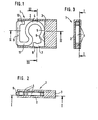
- a housing 1 made of one of the alloys common in dental technology e.g. made of a chromium-cobalt alloy or a noble metal alloy, is composed of a sleeve 2 and a solid material piece 3 that fills its hollow cross section over an end section of its length.
- the housing 1 is flat-cuboid. In the present example, its height is 0.9 mm, the length 50 mm, the width 35 mm and the wall thickness 0.2 mm.
- a spring 4 which is only curved within one plane. Its spring wire has a square cross section with an edge length of 0.4 mm in the present example.
- the spring 4 bears against the solid material piece 3 at two points 5 and 6.
- the end of the spring wire there is angled back in contact with the sleeve wall and provided with a kink 7, which is snapped into a recess 8 in the sleeve wall.
- the spring 4 lies with a straight section 9 in the open front side of the housing there.
- the spring wire end designated by 10
- the spring wire end is angled back in contact with the sleeve or housing wall.
- a straight section 11 which is angled on the other side of the housing cross section in the same way from the front section 9 of the spring, it forms a guide for the movement which the front section 9 of the spring has to carry out:
- the spring 4 serves with the front section 9 as a latch which engages in a notch. As can be seen in FIG. 2, the front edges of the spring wire on section 9 are chamfered for adaptation to the notch cross section.
- the notch is designated 12 in each of the application examples described below.
- FIG. 4 shows two teeth lying side by side, a crown 13 with a crown and a replacement tooth 15 seated on a prosthesis 14.
- the tooth 13 is provided with a conical inner crown 17 on its tooth stump 16, which is indicated by a broken line in outline.
- the housing 1 In a recess in the metal framework 20 of the prosthesis, the housing 1 has been installed, if necessary subsequently, by means of a plastic layer 21 shown in dotted lines. It is here provided on one side with anchors 22.
- the mentioned notch 12 is arranged on the conical inner crown 17 of the tooth 13.
- the front section 9 of the spring 4 engages in the notch 12.
- the prosthesis 14 is thereby held and can only be removed using greater tensile force.
- the solder layer 18 extends over a comparatively large cross section of the prosthesis.
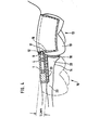
- FIG. 5 shows, in the situation perpendicular to FIG. 4, a left section of a prosthesis 23; the connecting bracket 24 to the right section has broken away at 25.
- the drawn left section of the prosthesis is attached and supported on a beam 26, which is firmly connected to two tooth crowns, one below and one above the drawing plane.
- the prosthesis 23 provides the tooth 27 of the lower jaw shown with a counter surface 28 and is provided on the outside with a covering 29 made of plastic or ceramic, which visually represents a tooth.
- the housing 1 is arranged in a recess of the prosthesis 23 dimensioned according to its size and fastened by means of a dotted plastic or solder layer 30.
- the notch 12, with which the spring 4 interacts as a locking element, is arranged in the bar 26.
- the housing 1 could be integrated here into the prosthesis 23 and largely even into the connecting bracket 24 and there is still sufficient space underneath for a plastic or solder layer 31 connecting the connecting bracket 24 to the rest of the prosthesis part.
- the housing 1 could also be cast on the connecting bracket 24.
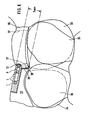
- FIG. 6 again shows two teeth, a tooth 32 with a crown and a replacement tooth 34 arranged on a prosthesis 33, side by side.
- teeth 32 and 34 two teeth 35 and 36 of the lower jaw appear in the drawing. They have largely oblique counter surfaces on teeth 32 and 34, respectively. This leads to an overlap in the drawing and leaves very little space for the prosthesis body and its metal frame.
- the crowning of the tooth 32 has two different parts, namely the part forming the tooth, to which the reference line 32 leads, and a part lying in front of this in the drawing of a substantially lower height, the prosthesis 33 as the inner crown 37 (shown in broken lines) carries, which is attached to the inner crown 37 with an outer crown 38.
- the notch 12 is arranged in the inner crown 37.
- the housing 1 with the spring 4, 9 which engages in the notch 12 as a locking element is cast into the metal structure of the prosthesis 33.
- a solder layer 39 connects this to the outer crown 38.
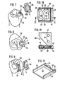
- Fig. 8 shows the assembled attachment in plan view.
- a half-box 40 with a cover 41 made of burnable model mass is provided.
- the half box 40 is produced from a sheet metal blank by folding side walls 42 and an end wall 43.
- the side walls 42 protrude beyond this with extensions 44 which are as long as the end wall 43 is high.
- the cover 41 made of model material encompasses the side walls 42 of the half box at 45.
- a fixed tooth crown 61 is designed as a attachment part with two grooves 62, and by engaging in it, a removable crown part 63 (FIG. 14) is to be put on, ie pushed on, which completes the replacement tooth and is used to fasten a prosthesis.
- the removable crown part 63 In order to be able to cast the removable crown part 63 in metal, it must be modeled in a burnable mass, usually wax, as a mold model 64 (FIGS. 16, 17) and embedded in a mold 65 in molding sand or another fireproof molding compound 66.
- a burnable mass usually wax
- FIGS. 16, 17 In order to be able to cast the removable crown part 63 in metal, it must be modeled in a burnable mass, usually wax, as a mold model 64 (FIGS. 16, 17) and embedded in a mold 65 in molding sand or another fireproof molding compound 66.
- the production of the mold model 64 using the mold model part 60 can be seen in FIG. 13 with two cutouts 67 and 68 in the hand-modeled part 69: the prefabricated mold model part 60 is with the open end face of the half box 40 and the cover 41 including the encircling 45 of the half box in the recess 68 and the handle and support member 47 are inserted with its front obtuse corner into the recess 68 so that the recesses are completely filled. Then the transition between the molded model part 60 and the hand-modeled part 69 around the recesses 64 and 68 is smoothed out by applying mass, which at the same time strengthens the connection.
- FIG. 13 also shows that the open end face of the half-box 40, in which the front of the spring 48 forming the latch is later located, lies exactly in front of a notch 70 incorporated in the fixed tooth crown 61, in which the spring is to engage.
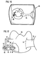
- FIG. 16 shows the mold model 64 in the casting mold 65, for which purpose the molding sand in the vicinity of the mold model 64 has been omitted and only the embedding of the extensions 44 of the side walls of the half-box 40 into the molding compound is shown.
- the importance of this embedding lies in the fact that, after the model mass has been burnt out and at the same time the cavity thus created has been filled with the liquid alloy, it holds the half-box 40 with the core filling it and prevents it because of the lighter specific weight of the core in the liquid alloy to be found.
- FIG. 17 where the half-box is, however, drawn without the core: without the embedding on the continuations 44, the half-box 40 could rise as much as the thickness of the cover 41, shown broken away is.
- the embedding holding the half box 40 ensures that the cover 41 and its encirclements 45 of the half box are completely molded in alloy become, so that then the half box, the material of which combines with that of the cast alloy, becomes an integral part of the casting.
- line 71 finally indicates how the metal residue 73 remaining in the pouring channel 72 (see FIG. 16) and sitting on the casting is cut off.
- FIG. 14 and 15 illustrate the function of the removable crown part 63 produced in the casting process in this way.
- FIG. 14 shows the crown part alone placed on the fixed tooth crown 61, the spring 48 engaging in the notch 70 therein.
- a prosthetic framework 74 is connected to the removable crown part 63, and in addition to the illustration in FIG. 15, replacement teeth are attached to it.
- the prosthesis part has two cheeks 75, which comprise the shaping of the previous grip and support part 47 of the molded model part 60 in the cast alloy and also have holes 46 in alignment with the holes thereof, so that one inserted through them Wire bracket 76 can secure the connection. All of this is enclosed in a replacement tooth.
- the prosthesis can be removed in that the removable crown part 63 can be removed from the fixed tooth crown 61 with a slight retraction of the spring 48 from the notch 70.
- FIG. 18 a casting core 77 is drawn in FIG. 18, which, as in the exemplary embodiment described above, was not inserted into a more extensive mold model part - which it could have been in a corresponding manner - but was incorporated into the mold model in pure laboratory work.
Landscapes
- Health & Medical Sciences (AREA)
- Oral & Maxillofacial Surgery (AREA)
- Dentistry (AREA)
- Epidemiology (AREA)
- Life Sciences & Earth Sciences (AREA)
- Animal Behavior & Ethology (AREA)
- General Health & Medical Sciences (AREA)
- Public Health (AREA)
- Veterinary Medicine (AREA)
- Dental Prosthetics (AREA)
- Dental Tools And Instruments Or Auxiliary Dental Instruments (AREA)
Priority Applications (1)
| Application Number | Priority Date | Filing Date | Title |
|---|---|---|---|
| AT84111623T ATE32176T1 (de) | 1983-10-03 | 1984-09-28 | Abnehmbare zahn-prothese sowie verfahren zu ihrer herstellung und hilfsmittel zur durchfuehrung des verfahrens. |
Applications Claiming Priority (4)
| Application Number | Priority Date | Filing Date | Title |
|---|---|---|---|
| DE3335904 | 1983-10-03 | ||
| DE3335904 | 1983-10-03 | ||
| DE3419359 | 1984-05-24 | ||
| DE3419359A DE3419359A1 (de) | 1983-10-03 | 1984-05-24 | Klemmvorrichtung zum befestigen einer abnehmbaren zahn-prothese sowie verfahren zu ihrer herstellung und hilfsmittel zur durchfuehrung des verfahrens |
Publications (3)
| Publication Number | Publication Date |
|---|---|
| EP0136671A2 true EP0136671A2 (fr) | 1985-04-10 |
| EP0136671A3 EP0136671A3 (fr) | 1985-05-08 |
| EP0136671B1 EP0136671B1 (fr) | 1988-01-27 |
Family
ID=25814552
Family Applications (1)
| Application Number | Title | Priority Date | Filing Date |
|---|---|---|---|
| EP84111623A Expired EP0136671B1 (fr) | 1983-10-03 | 1984-09-28 | Prothèse dentaire amovible et sa méthode de fabrication |
Country Status (4)
| Country | Link |
|---|---|
| US (2) | US4586902A (fr) |
| EP (1) | EP0136671B1 (fr) |
| JP (1) | JPH0616798B2 (fr) |
| DE (2) | DE3419359A1 (fr) |
Cited By (11)
| Publication number | Priority date | Publication date | Assignee | Title |
|---|---|---|---|---|
| EP0263235A1 (fr) * | 1986-04-29 | 1988-04-13 | Adam Obersat | Prothèse dentaire amovible et élément de construction pour sa fabrication |
| DE3838222A1 (de) * | 1988-11-11 | 1990-05-17 | Fr Konstruktionselemente Fuer | Feder eines riegelelementes fuer eine abnehmbare zahnprothese |
| DE8907997U1 (de) * | 1989-06-30 | 1990-11-08 | Obersat, Adam, 6750 Kaiserslautern | Vorrichtung zum Verriegeln eines herausnehmbaren Zahnprothesenteils an einem festsitzenden Zahnprothesenteil |
| EP0433934A1 (fr) * | 1989-12-16 | 1991-06-26 | Adam Obersat | Elément verrou, particulièrement pour une prothèse dentaire amovible |
| US5040985A (en) * | 1989-06-30 | 1991-08-20 | Adam Obersat | Attachment for releasably coupling components of dental prostheses |
| EP0499680A1 (fr) * | 1991-02-22 | 1992-08-26 | Adam Obersat | Couronne dentaire et élément de fixation rigide pour fixer une prothèse dentaire amovible |
| EP0504665A1 (fr) * | 1991-03-13 | 1992-09-23 | Adam Obersat | Elément de jonction pour prothèse dentaire |
| EP0514825A1 (fr) * | 1991-05-21 | 1992-11-25 | FR- KONSTRUKTIONSELEMENTE FÜR ZAHNPROTHETIK GmbH & CO | Ressort pour un élément de verrouillage pour une prothèse dentaire démontable |
| EP0490238A3 (en) * | 1990-12-12 | 1993-05-12 | Fr- Konstruktionselemente Fuer Zahnprothetik Gmbh & Co | Auxiliary element for removably securing a partial dental prosthesis to a fixed prosthetic element |
| WO2000003658A1 (fr) * | 1998-07-17 | 2000-01-27 | Universidade De Santiago De Compostela | Crochet de retenue remplaçable et crochet matrice pour dentitions adjointes partielles |
| WO2009147366A1 (fr) * | 2008-06-03 | 2009-12-10 | Rolls-Royce Plc | Moyen de fixation |
Families Citing this family (8)
| Publication number | Priority date | Publication date | Assignee | Title |
|---|---|---|---|---|
| DE59004746D1 (de) * | 1989-08-01 | 1994-04-07 | Adam Obersat | Anker zum Befestigen einer abnehmbaren Zahnprothese an einem festsitzenden Prothesenteil. |
| US5458489A (en) * | 1994-04-19 | 1995-10-17 | Tennyson; Philip C. | Tooth replacement assembly, and method |
| RU2146903C1 (ru) * | 1999-07-01 | 2000-03-27 | Рявкин Сергей Рудольфович | Способ зубочелюстного протезирования при дефектах альвеолярной части верхней челюсти |
| DE10325940B4 (de) * | 2003-06-07 | 2005-07-21 | Bennewart, Werner | Trägerelement für Zahnersatz |
| GB0822751D0 (en) * | 2008-12-15 | 2009-01-21 | 3M Innovative Properties Co | Method of making a dental restoration, and system for design and manufacturing a dental restoration |
| US8403671B2 (en) * | 2010-07-01 | 2013-03-26 | Tai-Wu LIN | Detachment-prevented removable double-crown prosthetic appliance |
| DE102012004991A1 (de) | 2012-03-13 | 2013-09-19 | Group Vander Kerken - Van Der Veken N.V. | Zahnprothesen-Stabilisator |
| WO2013183042A1 (fr) | 2012-06-04 | 2013-12-12 | SKVIRSKY, Igor | Dispositif pour la fixation amovible d'une prothèse dentaire |
Family Cites Families (5)
| Publication number | Priority date | Publication date | Assignee | Title |
|---|---|---|---|---|
| US1863230A (en) * | 1931-01-09 | 1932-06-14 | Jack L Shapiro | Dental bridgework attachment device |
| US2748480A (en) * | 1955-03-29 | 1956-06-05 | Weissman Bernard | Artificial denture |
| US3089242A (en) * | 1961-06-05 | 1963-05-14 | Weissman Bernard | Holding device for removable dental prosthesis |
| DE7035972U (de) * | 1970-09-29 | 1971-01-14 | Koenig Karl | Anker fuer zahnprothesen. |
| US4024211A (en) * | 1975-10-14 | 1977-05-17 | A. E. Strauss Company, Incorporated | Casting technique for prosthetic dentistry |
-
1984
- 1984-05-24 DE DE3419359A patent/DE3419359A1/de not_active Withdrawn
- 1984-09-21 JP JP19699284A patent/JPH0616798B2/ja not_active Expired - Lifetime
- 1984-09-26 US US06/655,025 patent/US4586902A/en not_active Expired - Lifetime
- 1984-09-28 EP EP84111623A patent/EP0136671B1/fr not_active Expired
- 1984-09-28 DE DE8484111623T patent/DE3468976D1/de not_active Expired
-
1986
- 1986-04-29 US US07/857,123 patent/US4773859A/en not_active Expired - Fee Related
Cited By (16)
| Publication number | Priority date | Publication date | Assignee | Title |
|---|---|---|---|---|
| EP0263235A1 (fr) * | 1986-04-29 | 1988-04-13 | Adam Obersat | Prothèse dentaire amovible et élément de construction pour sa fabrication |
| DE3838222A1 (de) * | 1988-11-11 | 1990-05-17 | Fr Konstruktionselemente Fuer | Feder eines riegelelementes fuer eine abnehmbare zahnprothese |
| DE8907997U1 (de) * | 1989-06-30 | 1990-11-08 | Obersat, Adam, 6750 Kaiserslautern | Vorrichtung zum Verriegeln eines herausnehmbaren Zahnprothesenteils an einem festsitzenden Zahnprothesenteil |
| US5040985A (en) * | 1989-06-30 | 1991-08-20 | Adam Obersat | Attachment for releasably coupling components of dental prostheses |
| EP0433934A1 (fr) * | 1989-12-16 | 1991-06-26 | Adam Obersat | Elément verrou, particulièrement pour une prothèse dentaire amovible |
| EP0490238A3 (en) * | 1990-12-12 | 1993-05-12 | Fr- Konstruktionselemente Fuer Zahnprothetik Gmbh & Co | Auxiliary element for removably securing a partial dental prosthesis to a fixed prosthetic element |
| EP0499680A1 (fr) * | 1991-02-22 | 1992-08-26 | Adam Obersat | Couronne dentaire et élément de fixation rigide pour fixer une prothèse dentaire amovible |
| US5266032A (en) * | 1991-02-22 | 1993-11-30 | Adam Obersat | Dental crown and rigid connector |
| US5297964A (en) * | 1991-02-22 | 1994-03-29 | Adam Obersat | Dental crown and rigid connector |
| EP0504665A1 (fr) * | 1991-03-13 | 1992-09-23 | Adam Obersat | Elément de jonction pour prothèse dentaire |
| US5275560A (en) * | 1991-03-13 | 1994-01-04 | Adam Obersat | Replaceable friction element for dental prosthesis |
| EP0514825A1 (fr) * | 1991-05-21 | 1992-11-25 | FR- KONSTRUKTIONSELEMENTE FÜR ZAHNPROTHETIK GmbH & CO | Ressort pour un élément de verrouillage pour une prothèse dentaire démontable |
| WO2000003658A1 (fr) * | 1998-07-17 | 2000-01-27 | Universidade De Santiago De Compostela | Crochet de retenue remplaçable et crochet matrice pour dentitions adjointes partielles |
| ES2150371A1 (es) * | 1998-07-17 | 2000-11-16 | Univ Santiago Compostela | Gancho retenedor recambiable y gancho matriz para dentaduras parciales removibles. |
| WO2009147366A1 (fr) * | 2008-06-03 | 2009-12-10 | Rolls-Royce Plc | Moyen de fixation |
| US8959737B2 (en) | 2008-06-03 | 2015-02-24 | Rolls-Royce Plc | Fixture means |
Also Published As
| Publication number | Publication date |
|---|---|
| JPH0616798B2 (ja) | 1994-03-09 |
| DE3468976D1 (en) | 1988-03-03 |
| US4586902A (en) | 1986-05-06 |
| EP0136671B1 (fr) | 1988-01-27 |
| EP0136671A3 (fr) | 1985-05-08 |
| JPS6088548A (ja) | 1985-05-18 |
| DE3419359A1 (de) | 1985-04-11 |
| US4773859A (en) | 1988-09-27 |
Similar Documents
| Publication | Publication Date | Title |
|---|---|---|
| EP0136671B1 (fr) | Prothèse dentaire amovible et sa méthode de fabrication | |
| DE2856963C1 (de) | Vorrichtung zum Herstellen eines zahntechnischen Arbeitsmodelles fuer die Anfertigung von prothetischen Arbeiten | |
| DE2730004C2 (de) | Verankerungsteil für Knochenendoprothesen | |
| DE69126324T2 (de) | Dentales modell sowie verfahren zum herstellen desselben | |
| DE2705768A1 (de) | Dentales modell sowie verfahren und einrichtung zu seiner herstellung | |
| DE3030274A1 (de) | Zahnsplint oder -klammer | |
| DE3201391C2 (de) | Geschiebeverbindung, sowie Verfahren und Vorrichtungzur Herstellung einer Geschiebeverbindung | |
| DE8909755U1 (de) | Teleskopkrone | |
| EP0172444A2 (fr) | Armature pour la réalisation de bridges dentaires | |
| DE69229797T2 (de) | Dentaler zahnstift mit sichtbarem, horizontalem index | |
| EP0161295B1 (en) | Device for binding parts of dental prosthesis by adhesion | |
| EP0745359A1 (fr) | Procédé pour la production d'un modèle dentaire et élément de retenue, plaque de base du modèle, plaque de positionnement et système de retenue pour sa mise en oeuvre | |
| DE3037595A1 (de) | Formkoerper zur erzeugung einer aussparung in einem betonfertigteil | |
| DE3204186A1 (de) | Flexibler haltesplint fuer zaehne | |
| DE3415653C2 (fr) | ||
| DE3504638C1 (de) | Vorrichtung zur lösbaren Befestigung einer zahntechnischen Teilprothese an Kronen oder anderen restgebißseitigen Gegenstücken | |
| CH700634A1 (de) | Vorrichtung zur Befestigung eines Zahnersatzes. | |
| DE3900168C2 (fr) | ||
| EP0263235A1 (fr) | Prothèse dentaire amovible et élément de construction pour sa fabrication | |
| DE1014286B (de) | Mit Metallverankerung versehener kuenstlicher Zahn | |
| DE3224487C2 (fr) | ||
| AT258459B (de) | Hilfsvorrichtung zur Herstellung eines einen abnehmbaren Zahnersatz mit den Restgebißpfeilerkronen verbindenden Geschiebes | |
| DE8328419U1 (de) | Rastvorrichtung zum befestigen einer abnehmbaren zahn-prothese | |
| EP0490238B1 (fr) | Elément destiné au verrouillage d'un appareil de prothèse dentaire amovible à un élément prothétique fixe | |
| DE10132219A1 (de) | Kronenlos verankerbares Zahnersatzelement |
Legal Events
| Date | Code | Title | Description |
|---|---|---|---|
| PUAI | Public reference made under article 153(3) epc to a published international application that has entered the european phase |
Free format text: ORIGINAL CODE: 0009012 |
|
| PUAL | Search report despatched |
Free format text: ORIGINAL CODE: 0009013 |
|
| AK | Designated contracting states |
Designated state(s): AT BE CH DE FR GB IT LI LU NL SE |
|
| AK | Designated contracting states |
Designated state(s): AT BE CH DE FR GB IT LI LU NL SE |
|
| RTI1 | Title (correction) | ||
| 17P | Request for examination filed |
Effective date: 19850913 |
|
| 17Q | First examination report despatched |
Effective date: 19860924 |
|
| GRAA | (expected) grant |
Free format text: ORIGINAL CODE: 0009210 |
|
| AK | Designated contracting states |
Kind code of ref document: B1 Designated state(s): AT BE CH DE FR GB IT LI LU NL SE |
|
| REF | Corresponds to: |
Ref document number: 32176 Country of ref document: AT Date of ref document: 19880215 Kind code of ref document: T |
|
| REF | Corresponds to: |
Ref document number: 3468976 Country of ref document: DE Date of ref document: 19880303 |
|
| ITF | It: translation for a ep patent filed | ||
| GBT | Gb: translation of ep patent filed (gb section 77(6)(a)/1977) | ||
| ET | Fr: translation filed | ||
| PLBE | No opposition filed within time limit |
Free format text: ORIGINAL CODE: 0009261 |
|
| STAA | Information on the status of an ep patent application or granted ep patent |
Free format text: STATUS: NO OPPOSITION FILED WITHIN TIME LIMIT |
|
| 26N | No opposition filed | ||
| PGFP | Annual fee paid to national office [announced via postgrant information from national office to epo] |
Ref country code: SE Payment date: 19910920 Year of fee payment: 8 |
|
| PGFP | Annual fee paid to national office [announced via postgrant information from national office to epo] |
Ref country code: LU Payment date: 19910924 Year of fee payment: 8 Ref country code: AT Payment date: 19910924 Year of fee payment: 8 |
|
| ITTA | It: last paid annual fee | ||
| EPTA | Lu: last paid annual fee | ||
| PG25 | Lapsed in a contracting state [announced via postgrant information from national office to epo] |
Ref country code: LU Free format text: LAPSE BECAUSE OF NON-PAYMENT OF DUE FEES Effective date: 19920928 Ref country code: AT Effective date: 19920928 |
|
| PG25 | Lapsed in a contracting state [announced via postgrant information from national office to epo] |
Ref country code: SE Effective date: 19920929 |
|
| PGFP | Annual fee paid to national office [announced via postgrant information from national office to epo] |
Ref country code: NL Payment date: 19940930 Year of fee payment: 11 |
|
| PGFP | Annual fee paid to national office [announced via postgrant information from national office to epo] |
Ref country code: BE Payment date: 19941007 Year of fee payment: 11 |
|
| EUG | Se: european patent has lapsed |
Ref document number: 84111623.9 Effective date: 19930406 |
|
| PGFP | Annual fee paid to national office [announced via postgrant information from national office to epo] |
Ref country code: FR Payment date: 19950807 Year of fee payment: 12 |
|
| PGFP | Annual fee paid to national office [announced via postgrant information from national office to epo] |
Ref country code: GB Payment date: 19950907 Year of fee payment: 12 |
|
| PG25 | Lapsed in a contracting state [announced via postgrant information from national office to epo] |
Ref country code: BE Effective date: 19950930 |
|
| BERE | Be: lapsed |
Owner name: OBERSAT ADAM Effective date: 19950930 |
|
| PG25 | Lapsed in a contracting state [announced via postgrant information from national office to epo] |
Ref country code: NL Effective date: 19960401 |
|
| NLV4 | Nl: lapsed or anulled due to non-payment of the annual fee |
Effective date: 19960401 |
|
| PG25 | Lapsed in a contracting state [announced via postgrant information from national office to epo] |
Ref country code: GB Effective date: 19960928 |
|
| PG25 | Lapsed in a contracting state [announced via postgrant information from national office to epo] |
Ref country code: FR Effective date: 19960930 |
|
| GBPC | Gb: european patent ceased through non-payment of renewal fee |
Effective date: 19960928 |
|
| REG | Reference to a national code |
Ref country code: FR Ref legal event code: ST |
|
| REG | Reference to a national code |
Ref country code: FR Ref legal event code: ST |
|
| PGFP | Annual fee paid to national office [announced via postgrant information from national office to epo] |
Ref country code: CH Payment date: 19990921 Year of fee payment: 16 |
|
| PGFP | Annual fee paid to national office [announced via postgrant information from national office to epo] |
Ref country code: DE Payment date: 19990927 Year of fee payment: 16 |
|
| PG25 | Lapsed in a contracting state [announced via postgrant information from national office to epo] |
Ref country code: LI Free format text: LAPSE BECAUSE OF NON-PAYMENT OF DUE FEES Effective date: 20000930 Ref country code: CH Free format text: LAPSE BECAUSE OF NON-PAYMENT OF DUE FEES Effective date: 20000930 |
|
| REG | Reference to a national code |
Ref country code: CH Ref legal event code: PL |
|
| PG25 | Lapsed in a contracting state [announced via postgrant information from national office to epo] |
Ref country code: DE Free format text: LAPSE BECAUSE OF NON-PAYMENT OF DUE FEES Effective date: 20010801 |