EP0136719A2 - Manipulateur - Google Patents
Manipulateur Download PDFInfo
- Publication number
- EP0136719A2 EP0136719A2 EP84111903A EP84111903A EP0136719A2 EP 0136719 A2 EP0136719 A2 EP 0136719A2 EP 84111903 A EP84111903 A EP 84111903A EP 84111903 A EP84111903 A EP 84111903A EP 0136719 A2 EP0136719 A2 EP 0136719A2
- Authority
- EP
- European Patent Office
- Prior art keywords
- arm
- articulate
- modules
- arm module
- module
- Prior art date
- Legal status (The legal status is an assumption and is not a legal conclusion. Google has not performed a legal analysis and makes no representation as to the accuracy of the status listed.)
- Granted
Links
Images


Classifications
-
- B—PERFORMING OPERATIONS; TRANSPORTING
- B25—HAND TOOLS; PORTABLE POWER-DRIVEN TOOLS; MANIPULATORS
- B25J—MANIPULATORS; CHAMBERS PROVIDED WITH MANIPULATION DEVICES
- B25J17/00—Joints
- B25J17/02—Wrist joints
-
- B—PERFORMING OPERATIONS; TRANSPORTING
- B25—HAND TOOLS; PORTABLE POWER-DRIVEN TOOLS; MANIPULATORS
- B25J—MANIPULATORS; CHAMBERS PROVIDED WITH MANIPULATION DEVICES
- B25J15/00—Gripping heads and other end effectors
- B25J15/02—Gripping heads and other end effectors servo-actuated
- B25J15/0253—Gripping heads and other end effectors servo-actuated comprising parallel grippers
- B25J15/0266—Gripping heads and other end effectors servo-actuated comprising parallel grippers actuated by articulated links
-
- B—PERFORMING OPERATIONS; TRANSPORTING
- B25—HAND TOOLS; PORTABLE POWER-DRIVEN TOOLS; MANIPULATORS
- B25J—MANIPULATORS; CHAMBERS PROVIDED WITH MANIPULATION DEVICES
- B25J9/00—Program-controlled manipulators
- B25J9/06—Program-controlled manipulators characterised by multi-articulated arms
-
- B—PERFORMING OPERATIONS; TRANSPORTING
- B25—HAND TOOLS; PORTABLE POWER-DRIVEN TOOLS; MANIPULATORS
- B25J—MANIPULATORS; CHAMBERS PROVIDED WITH MANIPULATION DEVICES
- B25J9/00—Program-controlled manipulators
- B25J9/08—Program-controlled manipulators characterised by modular constructions
Definitions
- the present invention relates to a manipulator and, more particularly, to a remote controlled manipulator which is suited for various tasks in places which are not easily accessible to operators.
- Japanese Patent Publication No. 37307/1972 discloses a known manipulator which makes use of wire ropes for transmitting the driving power
- Japanese Patent Laid-Open Publication No. 73463/1977 discloses a manipulator in which concentric driving cylindrical tubes are used for power transmission.
- the power transmission means extends through an interior of the manipulator arm and is connected to the respective shafts for articulating the adjacent arm sections. Therefore, the disassembly of the manipulator articulate portion'for the purpose of, for example, inspection requires demounting and remounting of the power trnamsission means onto the articulate portion, which makes the work difficult and time-consuming.
- Japanese Patent Laid-Open Publication No. 6272/ 1979 discloses a manipulator composed of a plurality of modules each of which can be detachably onto the next one without disassembly of other modules in order to improve the maintainability thereof.
- This publication discloses merely the basic concept for a module-type manipulator constituted by detachable modules, and fails to disclose practical and specific means for embodying such module mounting and demounting.
- the operation rate of the manipulator used in a remote controlled work in places where the operators do not have access to readily e.g., a high radioactive level area in a nuclear power plant, underwater, cosmic space and so forth, is affected by the maintainability of the manipulator itself.
- the manipulator requires to be assembled and disassembled in a short time. The task in such area, however, is quite severe and difficult even for the experts.
- the module-type manipulator composed of modules each of which can be detachably mounted onto the next one suffers from the following disadvantage in respect of the maintainability thereof. Namely, the cost of the manipulator is raised undesirably because of the necessity for the preparation of modules for maintaining the respective detachable modules.
- the provision of a plurality of power transmission lines, such as wire ropes or drive tubes, in the arm causes various types of inconvenience, e.g. an increase in the weight, complication in the construction and difficulties in the maintenance due to an increase of coupling elements between adjacent modules.
- an object of the present invention is to provide a manipulator having a higher flexibility and an improved maintainability.
- Another object of the present invention is to provide a manipulator in which a plurality of arm section swing angles in the articulate portions can be controlled by a single driving shaft unit and then the construction of the arm and articulate portion is very much simplified.
- the present invention aims at a provision of multi-articulate manipulator composed of a plurality of arm modules each having an articulate, wherein the arm modules is exchangeable one another and is constructed to be the same arrangement as another one.
- the present invention provides a multi-articulate manipulator composed of a plurality of arm modules having respective articulates, wherein each arm module is provided with an articulate address decoder and an articulate control circuit adapted to control a movement of the arm module in respect of the associated articulate portion, these circuits being connected to command circuits for commanding the articulate positions to be desired by means of address lines, data lines and a time-sharing control circuit.
- a first embodiment of the manipulator of the invention has a multi-articulate construction composed of a plurality of arm modules 2a to 2f articulated to each other to form an arm 2, and a gripper 3 articulated to an end of the distal arm module 2f.
- the proximal arm module 2a is connected to a base 4 which is mounted on a carrier 5 and then the manipulator 1 can be carried to any desired working place.
- the arm modules 2a to 2f have an identical construction.
- the construction of the arm module 2b will be explained by way of example.
- the arm module 2b has a hollow arm portion llb and an articulate portion 12b which is connected to the arm portion llb for swinging about an axis of an articulate shaft 13b.
- a drive shaft 14b extends through an interior of the arm portion llb.
- Bevel gears 15b and 16b are attached to both ends of the drive shaft 14b.
- the bevel gear 16b engages a bevel gear 17 which is fixed to an articulate shaft 25b.
- the arm modules 2a to 2f are so arranged that the axes of the articulate shafts 13a to 13f extend orthogonally to each other.
- the gripper 3 is coupled to the articulate portion 12f of the distal arm module 2f.
- the drive shafts 14a to 14f extending through the arm modules 2a to 2f are operatively connected in series through bevel gears 15a-15f, 16a-16f and 17a-17f.
- a motor 7 mounted within the base 4 has an output shaft 9 one end of which a bevel gear 10 is fixed to, which drives the bevel gear 15a through a bevel gear 18 lsee Fig. 3). so that he lovgue of the output shaft 9 of the motor 7 is transmitted to the drive shaft 14a and further to the series of drive shafts 14b to 14f through meshing bevel gears.
- the control system of this manipulator has an address line 110 and a data line 111 which constitute a bi-directional signal line, as well as a motor control line 112 and an encoder signal line 113.
- the address line 110 and the data line 111 are connected to the arm modules 2a-2f and further to the gripper 3 through the base 4.
- the motor contorl line 112 and the encoder signal line 113 are connected, respectively, to the motor 7 and the encoder 8 which are mounted within the base 4.
- the arm module will be more specifically explained with reference to Fig. 3 showing the arm module 2b.
- the arm portion llb has a concaved frusto-conical inner peripheral end surface.
- the outer peripheral end of the articulate portion 12b opposite to the frusto-conical end of the arm portion llb has a convexed frusto-conical surface.
- These frusto-conical surfaces complements each other so that the concaved and convexed frusto-conical surfaces of adjacent arm modules closely fit each other.
- the proximal frusto-conical concaved inner peripheral end surface of the arm portion llb of the arm module 2b closely fits the mating frusto-conical convexed peripheral end surface on the articulate portion 12a of the adjacent arm module 2a having the same construction as the arm module 2b.
- the frusto-conical.surface on the distal end of the articulate portion 12b fits the mating frusto-conical surface on the proximal end of the arm portion llc of the adjacent arm module 2c having the same construction as the arm module 2b.
- the drive shaft 14b is born by bearings 19b, 20b in the arm portion llb and carries bevel gears 15b and 16b at both ends thereof as explained before.
- the articulate 25b is mounted at the distal end of the arm portion llb for swinging about an axis 100b extending perpendicularly to the axis 102.
- the bevel gear 15b engages with the bevel gear 17a of the arm module 2a, while the bevel gear 17b engages with the bevel gear 15c of the arm module 2c.
- the bevel gears 17a and 17b have an identical construction.
- the bevel gears 15b and 15c have an identical construction.
- the articulate shaft 13b is coaxial with the shaft 25b and is fixed at its one end to the articulate portion 12b while at the other end is mounted on the arm portion llb through a bearing 26b.
- the articulate portion 12b is swingably mounted onto the arm portion llb through a bearing 27b.
- the axis of the bearing 26b and the articulate shaft 13b coincide with the axis 100b of the shaft 25b, so that the articulate portion 12b is swingable about the axis 100b, in directions of an arrow 101b.
- a clutch 23b and a brake 24b are mounted on the portion of the arm portion llb adjacent to the articulate shaft 13b.
- the clutch 23b has an input shaft 28b and an output shaft 29b which are connected to the shaft 25b and the articulate shaft 13b respectively through keys 31b and 32b.
- the clutch 23b also has a housing 33b fixed to a housing 34b of the brake 24b which in turn is fixed to the arm portion llb.
- the articulate shaft 13b extends through the center of the brake 24 and is coupled through a key 36b to the input shaft 35b of the brake 24b which is coaxial with the articulate shaft 13b.
- the clutch 23b and the brake 24b are of electromagnetic type and are adapted to be turned on when the electric power is not supplied thereto.
- an address decoder 40b and a control circuit 41b are provided within the arm portion llb.
- the address decoder 40b is connected to the address line 110 and also to the control circuit 41b through a control 'line 114b.
- the control circuit 41b is connected to the data line 111, and also to the clutch 23b and the brake 24b through an output line 115b for the clutch and an output line 116b for the brake.
- Terminals 42b are provided on ends of the address line 110 and the data line 111 respectively, while terminals 43b are provided on the other ends thereof.
- the terminals 42b are fixed to a surface on the arm portion llb fitting the articulate portion 12a of the adjacent arm module 2a, while the terminals 43b are fixed to a surface of the articulate portion 12b fitting the arm portion llc of the adjacent arm module 2c.
- the terminals 43b and 42b have mutually engageable constructions.
- the terminals 43b engage with the terminals 42c on the arm module 2c having an identical construction to the terminals 42b, while the terminals 42b are coupled to terminals 43a on the arm module 2 a having the same construction as the terminals 43b.
- the abovementioned coupling manner between the adjacent arm modules is applied to another arm modules 2a, 2c, 2d, 2e and 2f.
- the connection between the distal end arm module 2f and the gripper and the connection between the proximal end arm module 2a and the base 4 are made through specific coupling manners which are basically the same as the abovementioned coupling manner between adjacent arm modules.
- the coupling between the arm module 2a and the base 4 is achieved through a construction basically identical to that employed for the connection between adjacent arm modules, namely, through mutual engagement between the complemental frusto-conical surfaces.
- the arm portion 45 is fixed to the base 4 and supports a shaft 46 through bearings 47 and 48.
- the motor 7 is attached to the base 4 through a pedestal 49.
- the bevel gear 18 fixed to the shaft 46 engages both the bevel gears 10 and 15a such as to form a gear train through which the torque of the motor 7 is transmitted to the drive shaft 14a.
- Terminals 50 are provided on a distal end inner peripheral surface of the arm portion 45 and connected to the terminals 42a.
- the address line 110 and the data line 111 are connected to the terminals 50.
- the gripper 3 is coupled to the end of the articulate portion 12f of the distal arm module 2f, A bevel gear 52 is fixed to one end of the drive shaft 53 and meshes with the bevel gear 17f.
- the drive shaft 53 is supported within a housing 55 through a bearing 54.
- the other end of the drive shaft 53 is coupled to the input shaft of a clutch 56 fixed to the housing 55.
- An output shaft 58 of the clutch 56 extends through a brake 57 and is connected to the input shaft (not shown) of the brake 57.
- the brake 57 is fixed to the housing 55 through the housing 59.
- the bevel gear 60 is fixed to the end of the output shaft 58 and engages the gear units 61 and 62 which are mounted through bearings 63 on a post 64 fixed to the housing 55.
- each of the gear units 61 and 62 has a bevel gear 61a, 62a and a spur gear 61b, 62b which are provided on a single piece member.
- the bevel gears 61a, 62a engage a common bevel gear 60, while the spur gears 61b, 62b mesh spur gears 65, 66 which are provided on shafts 67 and 68, respectively.
- the shafts 67 and 68 are swingably mounted through bearings 69 onto posts 70, 71 fixed to the housing 55.
- Link members 72 and 73 are fixed at ones of their ends to the shafts 67 and 68 while the other ends of these link members are provided with fingers 75, 76 through bearings 74.
- Link members 77 and 78 are provided at both of their ends with shafts 79 and 80 which are mounted through bearings 74 to the housing 55 and the finger 75, respectively.
- the link members 72 and 77 constitute a parallelogram link mechanism.
- An identical parallelogram link mechanism is formed by the link members 73 and 78. Consequently, the fingers 75 and 76 are moved towards and away from each other while keeping the parallel relation therebetween, in accordance with the rotation of the shafts 67 and 68, thereby gripping and releasing an object.
- a rotation of the drive shaft 58 causes a rotation of the bevel gear 60 which in turn drives the gears 61 and 62 in the opposite directions. Consequently, the spur gears 65 and 66 meshing with these gears 61 and 62 also rotate in the opposite directions. This in turn drives the shafts 67 and 68 in the opposite directions so that the fingers 75 and 76 are moved towards or away from each other while keeping their gripping surfaces 81 and 82 in parallel with each other. Whether the fingers move towards or away from each other depends on the direction of rotation of the drive shaft 58. Namely, when the drive shaft 58 is rotated clockwise as viewed from the right side in the drawing, the fingers 75 and 76 are moved away from each other.
- the drive shaft 58 is driven by the motor 7 through the drive shafts 14a to 14f which are drivingly connected each other by the bevel gears 15a-15f, 16a-16f, 17a-17f, 10, 18 and 50.
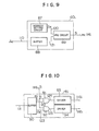
- the control system 6 of this manipulator has seven articulate angular position commanding circuits 85a to 85g and a time sharing control circuit 86 to which these circuits 85a to 85g are connected through the respective data lines 115.
- the commanding circuits 85a to 85f are adapted to command the corresponding angular positions of the articulates of the arm modules 2a to 2f, while the commanding circuit 85g commands the position of the fingers of the gripper 3.
- an address decoder 40g an articulate position control circuit 41g and associated signal lines are accommodated within the gripper 3.
- the required posture of the manipulator 1 at a certain moment is given in the form of command values of angular positions of the articulates issued from the articulate angular-position commanding circuits 85a-85g.
- the signals issued from the articulate angular position commanding circuits 85a-85g are delivered to the time-sharing control circuit 86.
- the time-sharing control circuit 86 is adapted to successively output the address codes Ac and the articulate control data Dc for respective arm modules 2a to 2f to the address line 110 and the data line 111, periodically.
- bit number k of the address signal is required to satisfy the following logarithmic function with the base 2: where, n represents the number of degrees of freedom of the manipulator.
- the required address bit number k has to be three or more (k ⁇ 3.
- the bit number k is selected to be four (4) so as to attain a greater adaptability or flexibility to any increase in the number of articulates.
- Table 1 shows an example of the address codes allotted for respective arm modules.
- the address decoder 40i (i: a ⁇ g) is composed of an address setting circuit 87, a buffer 88 and an AND circuit 89.
- the address setting circuit 87 has a plurality of switches which are adapted to be selectively turned on and off to produce peculiar address bit patterns A M which are delivered to the AND circuit 89 through a signal line 120.
- the buffer 88 is connected to the address line 110 and is connected to the AND circuit 89 through the signal line 120. The outputs from the AND circuit 89 is delivered to the control line 114i.
- the address code Ac from the time sharing circuit 86 to the address line is stored in the buffer 88 and is delivered to the AND circuit 89 through the control line 121.
- the AND circuit 89 computes the logical AND between the address bit pattern A M and the address code A c and deliveres a bit signal corresponding to the following output S to the control line 114i.
- the address setting means is so pre-setted that the address bit patterns A M for respective modules correspond to the patterns shown in Table 1.
- the articulate control circuit 41i (i: a ⁇ g) is composed of the following parts: namely, a buffer 90 to which the data line 111 and signal lines 122, 123 are connected; an AND circuit 91 to which the signal line 122, the control line 114i and the signal line 124 are connected; an AND circuit 92 to which the signal line 123, the control line 114i and the signal line 125 are connected; and drivers 93, 94 to which are connected signal lines 124, 125 and 115, 116, respectively.
- bit pattern of the 2-bit data Dc delivered to the data line 111 is expressed as follows: where, d C and d B represent the control signals for the clutch 23 and the brake 24, which take, respectively, a level “1" in the “on” state thereof and a level “0" in the “off” state thereof.
- the control signals d e and d B are delivered to the AND circuits 91 and 92 through the signal lines 122 and 123, so that the logical ANDs of these control signals d C and d b and the control signal S from the control line 114i are produced by these AND circuits.
- the driver 93 operates to turn the clutch on when the output from the associated AND circuit 91 is "1", while the driver 94 operates to release the brake when it receives the output "1" from the associated AND circuit 92.
- the clutch is "OFF” and the brake is “ON” when these conditions are not satisfied.
- the articulate control circuit in the arm module having the address pattern A M matching the address code A C delivered to the address line 110 is validated alone.
- the brake and the clutch associated with this arm module are driven to actuate the articulate of this arm module according to the data D C delivered to the data line 111.
- the amount of angular movement of the articulate is computed out on the basis of the variance in the encoder 8 during the period in which the same address bit pattern A M is maintained, which is inputted to the time-sharing circuit 86.
- the address code A is successively changed after a predetermined period so as to conform with the address bit patterns of successive articulates. Assume here that the address pattern A D has been maintained in conformity with the address bit pattern A M peculiar to one of the articulates. Then, immediately after the change of the address code, the amount of operation of this articulate is fed back to the articulate command control circuit of this articulate and is compared with the articulate angular-position command so as to produce a next command. After a predetermined time interval, the articulate control circuit of thi's articulate is validated again to effect a further control of the articulate position.
- the angular positions of the articulates of the arm modules are controlled and then the position of the distal end of the manipulator and the opening and closing position of the gripper are controlled.
- electric power supply lines are provided to supply respective circuits with electric power from a power source accommodated in the control system 6.
- the arm modules are arranged such that the articulate shafts of adjacent arm modules extend orthogonally each other.
- This, however, is not exclusive and the orientation of the arm modules 2a to 2f may be varied in various ways.
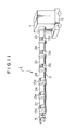
- Fig. 11 shows a modification in which the arm modules 2a, 2b, 2c are articulated such that their articulate axes 13a, 13b, 13c extend in parallel, while the arm modules 2d, 2e, 2f are articulated such that the articulate axes 13d, 13e, 13f thereof extend in parallel one another and extend perpendicular to the articulate axis 13c.
- the gripper can approach the object by detouring an obstacle 95 as schematically shown in Fig. 12.
- the construction of the arm and articulates can be very much simplified because the angular positions of all articulates can be controlled by means of a single drive shaft unit.
- Fig. 13 shows another embodiment having a construction of the arm modules 2a to 2f different from the construction of those shown in Fig. 3.
- this embodiment employs a motor 7b and an encoder 8b in place of the clutch 23b, brake 24b, drive shaft 14b, bevel gears 15b, 16b, 17b and other related elements, while the control line l14b leading from the address decoder 40b is substituted by lines 131b, 132b.
- an additional buffer 96b is used and a driver 97b is provided in place of the articulate control circuit 41b.
- two address bit patterns concerning the motor 7b and the encoder 8b are used as the code peculiar to the address code 97b.
- the address bit patterns are determined, for example, as shown in Table 2 below.
- the motor 7b includes a reduction gear (not shown) fixed to the arm portion llb.
- the output shaft of the motor 7b is connected to the articulate shaft 13b.
- the encoder 8b is fixed to the motor 7b so as to detect the angle of rotation of the motor output shaft.
- the driver 97b is enabled when the signal "1" is delivered thereto through the control line 131b, and delivers an output to the motor 7b, which corresponds to the signal transmitted through the data line 111.
- the buffer 96b latches the signal from the encoder 8b and delivers a latch signal to the data line 111 when the signal "1" is delivered through the control line 132b.
- this embodiment is distinguished from the preceding embodiment in that the angular positions of articulates are controlled through delivery of data concerning both the motors 7b and the encoders 8b.
- the independent servo system can be constituted with the respective are modules. Accordingly, even if the magnitude of the torque to be required for the respective arm modules is substantially different from one another, the angular position of the articulate portion of the arm module can be controlled rapidly because the change of the torque magnitude is not required between the arm modules.
- one or more articulates can be selectively controlled even through the control lines are common, so that the manipulator can be composed of a plurality of arm modules having an identical construction. This in turn allows free replacement or exchange of modules, rearrangement of degrees of freedom and increase or decrease of the degrees of freedom without requiring any change in the design.
- only one spare arm unit suffices as a common spare part for all arm modules.
Landscapes
- Engineering & Computer Science (AREA)
- Robotics (AREA)
- Mechanical Engineering (AREA)
- Manipulator (AREA)
Applications Claiming Priority (2)
| Application Number | Priority Date | Filing Date | Title |
|---|---|---|---|
| JP185050/83 | 1983-10-05 | ||
| JP58185050A JPS6080591A (ja) | 1983-10-05 | 1983-10-05 | マニプレ−タ |
Publications (3)
| Publication Number | Publication Date |
|---|---|
| EP0136719A2 true EP0136719A2 (fr) | 1985-04-10 |
| EP0136719A3 EP0136719A3 (en) | 1985-06-05 |
| EP0136719B1 EP0136719B1 (fr) | 1988-06-22 |
Family
ID=16163917
Family Applications (1)
| Application Number | Title | Priority Date | Filing Date |
|---|---|---|---|
| EP84111903A Expired EP0136719B1 (fr) | 1983-10-05 | 1984-10-04 | Manipulateur |
Country Status (4)
| Country | Link |
|---|---|
| US (1) | US4662814A (fr) |
| EP (1) | EP0136719B1 (fr) |
| JP (1) | JPS6080591A (fr) |
| DE (1) | DE3472230D1 (fr) |
Cited By (13)
| Publication number | Priority date | Publication date | Assignee | Title |
|---|---|---|---|---|
| GB2218399A (en) * | 1988-05-11 | 1989-11-15 | Danzoe Eng Ltd | Manipulator |
| US4973215A (en) * | 1986-02-18 | 1990-11-27 | Robotics Research Corporation | Industrial robot with servo |
| DE4431842A1 (de) * | 1994-09-07 | 1996-03-14 | Mathematik Und Datenverarbeitu | Elektronisch steuerbarer Automat |
| DE19518818A1 (de) * | 1995-05-23 | 1996-11-28 | Deutsche Forsch Luft Raumfahrt | Formveränderbarer Rahmen |
| EP1930129A4 (fr) * | 2005-09-27 | 2008-11-19 | Yaskawa Denki Seisakusho Kk | Manipulateur à articulations multiples |
| GB2455804A (en) * | 2007-12-21 | 2009-06-24 | Oliver Crispin Robotics Ltd | A robotic arm for use with a rotary machine |
| WO2011053209A1 (fr) * | 2009-10-30 | 2011-05-05 | Olaf Ruppel | Bras réglable pour moyens de préhension |
| EP2574427A1 (fr) * | 2011-09-30 | 2013-04-03 | Schunk GmbH & Co. KG Spann- und Greiftechnik | Module de manipulation, notamment module de saisie, module linéaire ou module rotatif, et dispositif de manipulation correspondant |
| US20150068347A1 (en) * | 2013-09-10 | 2015-03-12 | Seiko Epson Corporation | Robot arm and robot |
| CN105522589A (zh) * | 2015-11-06 | 2016-04-27 | 中国矿业大学 | 一种模块化可折叠式机械臂单元 |
| CN105798896A (zh) * | 2016-05-30 | 2016-07-27 | 天津大学 | 一种基于气压锁定原理的变刚度连续型机构 |
| US20180009111A1 (en) * | 2016-07-06 | 2018-01-11 | Inventec Appliances (Pudong) Corporation | Multiaxial robot of multitasking |
| US10099367B2 (en) | 2013-09-10 | 2018-10-16 | Seiko Epson Corporation | Robot arm and robot |
Families Citing this family (52)
| Publication number | Priority date | Publication date | Assignee | Title |
|---|---|---|---|---|
| DE3423432C2 (de) * | 1984-06-26 | 1986-06-12 | Deutsche Forschungs- und Versuchsanstalt für Luft- und Raumfahrt e.V., 5000 Köln | Vorrichtung zur Positionierung einer Probe |
| US5155423A (en) * | 1986-02-18 | 1992-10-13 | Robotics Research Corporation | Industrial robot with servo |
| US4822238A (en) * | 1986-06-19 | 1989-04-18 | Westinghouse Electric Corp. | Robotic arm |
| FR2620837B1 (fr) * | 1987-09-21 | 1990-11-30 | Commissariat Energie Atomique | Dispositif d'orientation d'un objet autour de deux axes de rotation |
| JPH0192390U (fr) * | 1987-12-10 | 1989-06-16 | ||
| US5046914A (en) * | 1988-07-12 | 1991-09-10 | Cybermation, Inc. | Parallel lifting device |
| US5249479A (en) * | 1988-10-24 | 1993-10-05 | Fanuc Ltd. | Wrist mechanism for an industrial robot |
| US4949586A (en) * | 1988-11-07 | 1990-08-21 | Intelmatic Corp. | Actuator swing arm mechanism |
| US5142211A (en) * | 1990-04-16 | 1992-08-25 | Progressive Blasting Systems, Inc. | Five-axis robot |
| US5245263A (en) * | 1991-09-13 | 1993-09-14 | University Of Maryland | Anti-backlash drive systems for multi-degree freedom devices |
| EP0601239B1 (fr) * | 1992-12-09 | 1997-03-19 | Ihc Holland N.V. | Dispositif pour l'entraînement d'un outil disposé sur une partie pivotante |
| US5656904A (en) * | 1995-09-28 | 1997-08-12 | Lander; Ralph | Movement monitoring and control apparatus for body members |
| US6686717B2 (en) * | 1997-04-01 | 2004-02-03 | Charles Khairallah | Modular articulated structure |
| FR2810573B1 (fr) * | 2000-06-21 | 2002-10-11 | Commissariat Energie Atomique | Bras de commande a deux branches en parallele |
| US6454624B1 (en) * | 2001-08-24 | 2002-09-24 | Xerox Corporation | Robotic toy with posable joints |
| US7073271B2 (en) * | 2002-02-14 | 2006-07-11 | Faro Technologies Inc. | Portable coordinate measurement machine |
| US7519493B2 (en) * | 2002-02-14 | 2009-04-14 | Faro Technologies, Inc. | Portable coordinate measurement machine with integrated line laser scanner |
| US6957496B2 (en) * | 2002-02-14 | 2005-10-25 | Faro Technologies, Inc. | Method for improving measurement accuracy of a portable coordinate measurement machine |
| USRE42082E1 (en) | 2002-02-14 | 2011-02-01 | Faro Technologies, Inc. | Method and apparatus for improving measurement accuracy of a portable coordinate measurement machine |
| US7246030B2 (en) * | 2002-02-14 | 2007-07-17 | Faro Technologies, Inc. | Portable coordinate measurement machine with integrated line laser scanner |
| US6952882B2 (en) * | 2002-02-14 | 2005-10-11 | Faro Technologies, Inc. | Portable coordinate measurement machine |
| EP1474653B1 (fr) * | 2002-02-14 | 2013-01-02 | Faro Technologies Inc. | Machine portable de mesure de coordonnees avec appareil laser a balayage lineaire |
| US7881896B2 (en) | 2002-02-14 | 2011-02-01 | Faro Technologies, Inc. | Portable coordinate measurement machine with integrated line laser scanner |
| US6973734B2 (en) * | 2002-02-14 | 2005-12-13 | Faro Technologies, Inc. | Method for providing sensory feedback to the operator of a portable measurement machine |
| WO2004103649A1 (fr) * | 2003-05-20 | 2004-12-02 | Fujitsu Limited | Procede de reglage de rattrapage de jeu, controleur de rattrapage de jeu et programme de reglage de rattrapage de jeu |
| DE102004030536A1 (de) * | 2004-06-24 | 2006-01-12 | Siemens Ag | Verfahren zur Ermittlung des Risikos für einen störungsfreien Betrieb eines Frequenzumrichters |
| JP2006026806A (ja) * | 2004-07-16 | 2006-02-02 | Harmonic Drive Syst Ind Co Ltd | ロボットハンド等の関節機構 |
| JP4457794B2 (ja) * | 2004-07-22 | 2010-04-28 | トヨタ自動車株式会社 | ロボット |
| JP2007152528A (ja) * | 2005-12-08 | 2007-06-21 | Ario Techno Kk | 関節装置、関節装置を用いたフィンガーユニット、及び、ユニバーサルロボットハンド |
| WO2010101203A1 (fr) * | 2009-03-06 | 2010-09-10 | 株式会社安川電機 | Unité d'articulation pour robot et robot |
| US8498741B2 (en) * | 2009-09-22 | 2013-07-30 | Gm Global Technology Operations | Dexterous humanoid robotic wrist |
| US9140344B2 (en) * | 2010-10-01 | 2015-09-22 | Industrial Technology Research Institute | Differential-velocity driving device and mechanical arm to which the differential-velocity driving device is applied |
| TWI401144B (zh) * | 2010-10-01 | 2013-07-11 | Ind Tech Res Inst | 高反應力關節裝置的控制方法 |
| JP2011075569A (ja) * | 2010-10-02 | 2011-04-14 | International Rescue System Institute | フレキシブルセンサチューブ |
| TW201219175A (en) * | 2010-11-05 | 2012-05-16 | Hon Hai Prec Ind Co Ltd | Power switching appratus |
| CN103596733A (zh) * | 2011-06-01 | 2014-02-19 | 株式会社安川电机 | 多关节机器人 |
| US9267585B2 (en) | 2011-06-02 | 2016-02-23 | Empire Technology Development Llc | Actuator with joints |
| ITMI20111920A1 (it) * | 2011-10-24 | 2013-04-25 | Milano Politecnico | Architettura di robot articolato per uso medico. |
| DE102012220415A1 (de) * | 2012-11-09 | 2014-05-28 | Robert Bosch Gmbh | Handwerkzeuggetriebeeinheit |
| JP2014217899A (ja) * | 2013-05-07 | 2014-11-20 | 矢継 正信 | 入れ子構造のユニバーサルジョイント |
| JPWO2016152987A1 (ja) * | 2015-03-25 | 2018-01-18 | ソニー・オリンパスメディカルソリューションズ株式会社 | 医療用観察装置、手術用観察装置及び医療用観察システム |
| US10035261B2 (en) * | 2016-06-17 | 2018-07-31 | Schaeffler Technologies AG & Co. KG | Actuatable joint for a robotic system having an axial angular contact roller bearing |
| CN107225597B (zh) * | 2017-07-24 | 2020-05-15 | 中国电子科技集团公司第二十一研究所 | 一种基于中空一体电机的两自由度模块化关节组件 |
| JP7250758B2 (ja) | 2017-08-10 | 2023-04-03 | プロ-デツクス・インコーポレイテツド | 締結具の内視鏡的留置のための関節動作ツール |
| CN108044599B (zh) * | 2018-01-23 | 2020-12-15 | 台州技创机械科技有限公司 | 一种应用于强磁场强辐射工况的检修机械臂装置 |
| CN108189002B (zh) * | 2018-01-23 | 2021-01-01 | 江苏铁锚玻璃股份有限公司 | 一种应用于恶劣工况的压电超声振子驱动型检修机械臂 |
| CN108312140A (zh) * | 2018-03-28 | 2018-07-24 | 陕西蓝智机器人有限公司 | 一种单机轴联式多自由度关节机械臂 |
| CN108946138B (zh) * | 2018-06-27 | 2023-10-31 | 江苏伟正电气科技有限公司 | 一种电池的防脱落机构 |
| CN109591020B (zh) * | 2019-01-21 | 2023-02-28 | 兰州大学 | 一种多冗余度机械臂自适应可操纵性最优化的分布式协同控制方法与装置 |
| US12349902B2 (en) * | 2020-07-09 | 2025-07-08 | Covidien Lp | Powered handle assembly for surgical devices |
| CN113183123A (zh) * | 2021-04-15 | 2021-07-30 | 浙江工业大学 | 一种刚柔耦合灵巧手的可变刚度单指骨架 |
| JP2026507250A (ja) * | 2023-03-03 | 2026-02-27 | ノーグレン オートメーション ソリューションズ,リミティド ライアビリティ カンパニー | 工具類ジョイントに関連するシステムおよびアセンブリ |
Family Cites Families (15)
| Publication number | Priority date | Publication date | Assignee | Title |
|---|---|---|---|---|
| SU197708A1 (ru) * | 1966-03-23 | 1973-01-08 | ВСЕСОЮЗНАЯ IШ.-уул -•'УУк''ГГ<(.?>&'?3! tHihl^it-Abfr:'.- EUi.'tiБ^'-|€:ЛИО^ТКА (ТЕРЛ10 | |
| SU524685A2 (ru) * | 1975-06-16 | 1976-08-15 | Казахский Ордена Трудового Красного Знамени Государственный Университет Им.С.М.Кирова | Манипул тор |
| SU814718A1 (ru) * | 1978-10-02 | 1981-03-23 | Казахский Ордена Трудового Крас-Ного Знамени Государственныйуниверситет Им. C.M.Кирова | Исполнительный орган манипул тора |
| US4221997A (en) * | 1978-12-18 | 1980-09-09 | Western Electric Company, Incorporated | Articulated robot arm and method of moving same |
| DE3034912A1 (de) * | 1979-09-17 | 1981-04-02 | Kurt Dipl.-Ing. Steinmaur Ehrat | Industrieroboter |
| US4283764A (en) * | 1979-10-12 | 1981-08-11 | Nordson Corporation | Manually programmable robot with power-assisted motion during programming |
| JPS584382A (ja) * | 1981-06-26 | 1983-01-11 | ファナック株式会社 | 工業用ロボツトの制御方式 |
| GB2102590A (en) * | 1981-07-23 | 1983-02-02 | Custom Microdesign | Digital movement controller for automatic multi-axis machines |
| JPS5851090A (ja) * | 1981-09-21 | 1983-03-25 | 株式会社東芝 | 関節装置 |
| JPS58132490A (ja) * | 1982-01-29 | 1983-08-06 | 株式会社日立製作所 | 角度伝達機構 |
| US4561816A (en) * | 1982-08-30 | 1985-12-31 | Dingess Billy E | Remote manipulator arm for nuclear generator repair |
| US4502347A (en) * | 1982-09-21 | 1985-03-05 | Westinghouse Electric Corp. | Robotic wrist |
| US4531884A (en) * | 1982-11-15 | 1985-07-30 | Russell Richard H | Automated machine |
| JPS59175987A (ja) * | 1983-03-26 | 1984-10-05 | 株式会社東芝 | 多関節ロボツト装置 |
| JPS59196185A (ja) * | 1983-04-22 | 1984-11-07 | 株式会社東芝 | 多関節ア−ムの信号伝送装置 |
-
1983
- 1983-10-05 JP JP58185050A patent/JPS6080591A/ja active Granted
-
1984
- 1984-10-04 US US06/657,500 patent/US4662814A/en not_active Expired - Lifetime
- 1984-10-04 EP EP84111903A patent/EP0136719B1/fr not_active Expired
- 1984-10-04 DE DE8484111903T patent/DE3472230D1/de not_active Expired
Cited By (24)
| Publication number | Priority date | Publication date | Assignee | Title |
|---|---|---|---|---|
| US4973215A (en) * | 1986-02-18 | 1990-11-27 | Robotics Research Corporation | Industrial robot with servo |
| US5581166A (en) * | 1986-02-18 | 1996-12-03 | Robotics Research Corporation | Industrial robot with servo |
| GB2218399A (en) * | 1988-05-11 | 1989-11-15 | Danzoe Eng Ltd | Manipulator |
| DE4431842A1 (de) * | 1994-09-07 | 1996-03-14 | Mathematik Und Datenverarbeitu | Elektronisch steuerbarer Automat |
| DE4431842C2 (de) * | 1994-09-07 | 1998-10-01 | Gmd Gmbh | Elektronisch steuerbare Vorrichtung |
| DE19518818A1 (de) * | 1995-05-23 | 1996-11-28 | Deutsche Forsch Luft Raumfahrt | Formveränderbarer Rahmen |
| CN101272886B (zh) * | 2005-09-27 | 2012-10-24 | 株式会社安川电机 | 多关节机械手、机器人系统以及双臂多关节机械手 |
| US8413538B2 (en) | 2005-09-27 | 2013-04-09 | Kabushiki Kaisha Yaskawa Denki | Articulated manipulator |
| EP1930129A4 (fr) * | 2005-09-27 | 2008-11-19 | Yaskawa Denki Seisakusho Kk | Manipulateur à articulations multiples |
| EP2113343A3 (fr) * | 2005-09-27 | 2010-01-13 | Kabushiki Kaisha Yaskawa Denki | Manipulateur multipoint |
| US7971504B2 (en) | 2005-09-27 | 2011-07-05 | Kabushiki Kaisha Yaskawa Denki | Articulated manipulator |
| WO2009081164A1 (fr) * | 2007-12-21 | 2009-07-02 | Oliver Crispin Robotics Limited | Bras robotique |
| US8374722B2 (en) | 2007-12-21 | 2013-02-12 | Oliver Crispin Robotics Limited | Robotic arm |
| GB2455804A (en) * | 2007-12-21 | 2009-06-24 | Oliver Crispin Robotics Ltd | A robotic arm for use with a rotary machine |
| WO2011053209A1 (fr) * | 2009-10-30 | 2011-05-05 | Olaf Ruppel | Bras réglable pour moyens de préhension |
| EP2574427A1 (fr) * | 2011-09-30 | 2013-04-03 | Schunk GmbH & Co. KG Spann- und Greiftechnik | Module de manipulation, notamment module de saisie, module linéaire ou module rotatif, et dispositif de manipulation correspondant |
| US9802327B2 (en) * | 2013-09-10 | 2017-10-31 | Seiko Epson Corporation | Robot arm and robot |
| US9796097B2 (en) | 2013-09-10 | 2017-10-24 | Seiko Epson Corporation | Robot and manufacturing method for robot |
| US20150068347A1 (en) * | 2013-09-10 | 2015-03-12 | Seiko Epson Corporation | Robot arm and robot |
| US10099367B2 (en) | 2013-09-10 | 2018-10-16 | Seiko Epson Corporation | Robot arm and robot |
| CN105522589A (zh) * | 2015-11-06 | 2016-04-27 | 中国矿业大学 | 一种模块化可折叠式机械臂单元 |
| CN105798896A (zh) * | 2016-05-30 | 2016-07-27 | 天津大学 | 一种基于气压锁定原理的变刚度连续型机构 |
| US20180009111A1 (en) * | 2016-07-06 | 2018-01-11 | Inventec Appliances (Pudong) Corporation | Multiaxial robot of multitasking |
| US10399226B2 (en) * | 2016-07-06 | 2019-09-03 | Inventec Appliances (Pudong) Corporation | Multiaxial robot of multitasking |
Also Published As
| Publication number | Publication date |
|---|---|
| JPH0234757B2 (fr) | 1990-08-06 |
| EP0136719B1 (fr) | 1988-06-22 |
| DE3472230D1 (en) | 1988-07-28 |
| JPS6080591A (ja) | 1985-05-08 |
| US4662814A (en) | 1987-05-05 |
| EP0136719A3 (en) | 1985-06-05 |
Similar Documents
| Publication | Publication Date | Title |
|---|---|---|
| EP0136719A2 (fr) | Manipulateur | |
| US12036667B2 (en) | Gear packaging for robotic joints | |
| EP0279591A1 (fr) | Manipulateur robotisé | |
| CA1065365A (fr) | Robot | |
| EP0172603B1 (fr) | Ensemble de bras inférieur pour robot industriel | |
| US7281447B2 (en) | Articulated mechanism comprising a cable reduction gear for use in a robot arm | |
| EP1694472B1 (fr) | Manipulateur cinematique parallele pour espace de travail etendu | |
| US7337691B2 (en) | Parallel kinematics mechanism with a concentric spherical joint | |
| DE69416598T2 (de) | Roboter ohne kabelverbindung | |
| EP0210490B1 (fr) | Engrenage pour main de robot à trois degrés de liberté | |
| US11938624B2 (en) | Parallel kinematic robot | |
| WO2011003451A1 (fr) | Système de bras de robot et bras de robot | |
| EP0022332A1 (fr) | Robots industriels | |
| CN115741660A (zh) | 一种双关节多自由度机械臂及其驱动方法 | |
| US6336374B1 (en) | Device for relative displacement of two elements | |
| EP0128544B1 (fr) | Structure de joint entre des membres de jonction, particulièrement d'un bras de robot industriel | |
| JPH02298482A (ja) | 垂直多関節形ロボット | |
| CN114043468B (zh) | 一种基于球形齿轮及齿条传动的模块化等曲率机械臂 | |
| JPH05237779A (ja) | 遠隔操作マニュピュレータ用関節モジュールおよび遠隔操作マニュピュレータ | |
| US11420324B2 (en) | Parallel link robot | |
| US20050072260A1 (en) | Method for driving multiple-module mechanisms by a single motor and redundant modular robots produced therefrom | |
| JPS61236493A (ja) | 多関節ロボツトア−ム | |
| CN209793719U (zh) | 一种机械手联接支架组件 | |
| CN1228171C (zh) | 一类三自由度空间并联机器人机构 | |
| JPH01247844A (ja) | 駆動機構 |
Legal Events
| Date | Code | Title | Description |
|---|---|---|---|
| PUAI | Public reference made under article 153(3) epc to a published international application that has entered the european phase |
Free format text: ORIGINAL CODE: 0009012 |
|
| PUAL | Search report despatched |
Free format text: ORIGINAL CODE: 0009013 |
|
| AK | Designated contracting states |
Designated state(s): DE FR GB SE |
|
| AK | Designated contracting states |
Designated state(s): DE FR GB SE |
|
| 17P | Request for examination filed |
Effective date: 19850607 |
|
| 17Q | First examination report despatched |
Effective date: 19860901 |
|
| GRAA | (expected) grant |
Free format text: ORIGINAL CODE: 0009210 |
|
| AK | Designated contracting states |
Kind code of ref document: B1 Designated state(s): DE FR GB SE |
|
| REF | Corresponds to: |
Ref document number: 3472230 Country of ref document: DE Date of ref document: 19880728 |
|
| ET | Fr: translation filed | ||
| PLBE | No opposition filed within time limit |
Free format text: ORIGINAL CODE: 0009261 |
|
| STAA | Information on the status of an ep patent application or granted ep patent |
Free format text: STATUS: NO OPPOSITION FILED WITHIN TIME LIMIT |
|
| 26N | No opposition filed | ||
| PGFP | Annual fee paid to national office [announced via postgrant information from national office to epo] |
Ref country code: GB Payment date: 19910808 Year of fee payment: 8 |
|
| PGFP | Annual fee paid to national office [announced via postgrant information from national office to epo] |
Ref country code: SE Payment date: 19910906 Year of fee payment: 8 |
|
| PGFP | Annual fee paid to national office [announced via postgrant information from national office to epo] |
Ref country code: FR Payment date: 19910918 Year of fee payment: 8 |
|
| PG25 | Lapsed in a contracting state [announced via postgrant information from national office to epo] |
Ref country code: GB Effective date: 19921004 |
|
| PG25 | Lapsed in a contracting state [announced via postgrant information from national office to epo] |
Ref country code: SE Effective date: 19921005 |
|
| GBPC | Gb: european patent ceased through non-payment of renewal fee |
Effective date: 19921004 |
|
| PG25 | Lapsed in a contracting state [announced via postgrant information from national office to epo] |
Ref country code: FR Effective date: 19930630 |
|
| REG | Reference to a national code |
Ref country code: FR Ref legal event code: ST |
|
| PGFP | Annual fee paid to national office [announced via postgrant information from national office to epo] |
Ref country code: DE Payment date: 19931228 Year of fee payment: 10 |
|
| EUG | Se: european patent has lapsed |
Ref document number: 84111903.5 Effective date: 19930510 |
|
| PG25 | Lapsed in a contracting state [announced via postgrant information from national office to epo] |
Ref country code: DE Effective date: 19950701 |