EP0136740A1 - Verfahren zur Herstellung von Paketen ringförmiger, magnetischer oder anderer Bleche und Anlage zu dessen Durchführung - Google Patents
Verfahren zur Herstellung von Paketen ringförmiger, magnetischer oder anderer Bleche und Anlage zu dessen Durchführung Download PDFInfo
- Publication number
- EP0136740A1 EP0136740A1 EP84201144A EP84201144A EP0136740A1 EP 0136740 A1 EP0136740 A1 EP 0136740A1 EP 84201144 A EP84201144 A EP 84201144A EP 84201144 A EP84201144 A EP 84201144A EP 0136740 A1 EP0136740 A1 EP 0136740A1
- Authority
- EP
- European Patent Office
- Prior art keywords
- sheet metal
- segments
- package
- station
- layers
- Prior art date
- Legal status (The legal status is an assumption and is not a legal conclusion. Google has not performed a legal analysis and makes no representation as to the accuracy of the status listed.)
- Granted
Links
- 238000000034 method Methods 0.000 title claims abstract description 18
- 238000004519 manufacturing process Methods 0.000 title claims abstract description 8
- 238000009434 installation Methods 0.000 title claims description 23
- 239000002184 metal Substances 0.000 claims abstract description 54
- 238000002788 crimping Methods 0.000 claims abstract description 16
- 230000002093 peripheral effect Effects 0.000 claims abstract description 6
- 230000015572 biosynthetic process Effects 0.000 claims abstract description 4
- 238000003754 machining Methods 0.000 claims description 6
- 238000005259 measurement Methods 0.000 claims description 6
- 229910001209 Low-carbon steel Inorganic materials 0.000 claims description 4
- 230000008719 thickening Effects 0.000 claims description 3
- 230000000295 complement effect Effects 0.000 claims description 2
- 230000000717 retained effect Effects 0.000 claims description 2
- 238000005520 cutting process Methods 0.000 abstract description 2
- 238000010276 construction Methods 0.000 description 3
- 239000010814 metallic waste Substances 0.000 description 2
- 210000000056 organ Anatomy 0.000 description 2
- 239000002699 waste material Substances 0.000 description 2
- 238000003466 welding Methods 0.000 description 2
- 230000003416 augmentation Effects 0.000 description 1
- 230000007547 defect Effects 0.000 description 1
- 239000000725 suspension Substances 0.000 description 1
Images

Classifications
-
- H—ELECTRICITY
- H02—GENERATION; CONVERSION OR DISTRIBUTION OF ELECTRIC POWER
- H02K—DYNAMO-ELECTRIC MACHINES
- H02K15/00—Processes or apparatus specially adapted for manufacturing, assembling, maintaining or repairing of dynamo-electric machines
- H02K15/02—Processes or apparatus specially adapted for manufacturing, assembling, maintaining or repairing of dynamo-electric machines of stator or rotor bodies
- H02K15/021—Magnetic cores
-
- Y—GENERAL TAGGING OF NEW TECHNOLOGICAL DEVELOPMENTS; GENERAL TAGGING OF CROSS-SECTIONAL TECHNOLOGIES SPANNING OVER SEVERAL SECTIONS OF THE IPC; TECHNICAL SUBJECTS COVERED BY FORMER USPC CROSS-REFERENCE ART COLLECTIONS [XRACs] AND DIGESTS
- Y10—TECHNICAL SUBJECTS COVERED BY FORMER USPC
- Y10T—TECHNICAL SUBJECTS COVERED BY FORMER US CLASSIFICATION
- Y10T29/00—Metal working
- Y10T29/49—Method of mechanical manufacture
- Y10T29/49002—Electrical device making
- Y10T29/49009—Dynamoelectric machine
-
- Y—GENERAL TAGGING OF NEW TECHNOLOGICAL DEVELOPMENTS; GENERAL TAGGING OF CROSS-SECTIONAL TECHNOLOGIES SPANNING OVER SEVERAL SECTIONS OF THE IPC; TECHNICAL SUBJECTS COVERED BY FORMER USPC CROSS-REFERENCE ART COLLECTIONS [XRACs] AND DIGESTS
- Y10—TECHNICAL SUBJECTS COVERED BY FORMER USPC
- Y10T—TECHNICAL SUBJECTS COVERED BY FORMER US CLASSIFICATION
- Y10T29/00—Metal working
- Y10T29/53—Means to assemble or disassemble
- Y10T29/5313—Means to assemble electrical device
- Y10T29/53143—Motor or generator
- Y10T29/53161—Motor or generator including deforming means
-
- Y—GENERAL TAGGING OF NEW TECHNOLOGICAL DEVELOPMENTS; GENERAL TAGGING OF CROSS-SECTIONAL TECHNOLOGIES SPANNING OVER SEVERAL SECTIONS OF THE IPC; TECHNICAL SUBJECTS COVERED BY FORMER USPC CROSS-REFERENCE ART COLLECTIONS [XRACs] AND DIGESTS
- Y10—TECHNICAL SUBJECTS COVERED BY FORMER USPC
- Y10T—TECHNICAL SUBJECTS COVERED BY FORMER US CLASSIFICATION
- Y10T29/00—Metal working
- Y10T29/53—Means to assemble or disassemble
- Y10T29/5313—Means to assemble electrical device
- Y10T29/5317—Laminated device
Definitions
- the present invention relates to a method of manufacturing packages of magnetic or other sheets of annular shape for small and medium electric machines, in particular alternators for motor vehicles, from stamped sheets, having slots open inwards having a narrowing at their entry and which are formed by arms directed radially inward and thickening at their end.
- the invention also relates to an installation for implementing the method.
- the present invention aims to overcome these drawbacks by proposing a method of manufacturing packages and assembling magnetic or other sheets of annular shape making it possible on the one hand to reduce the quantity of waste and on the other hand to eliminate internal tensions of the stamped rings thus making it possible to respect the required tolerances without any subsequent machining of the stator.
- the essential advantage of the invention is linked to the fact that a ring is formed by juxtaposed segments, their number possibly varying from two to six but preferably three are used. In this way, one eliminates on the one hand the internal tensions created on a closed ring during the stamping thus allowing the respect of the required tolerances without a machining of the stator is necessary, and on the other hand the quantity of sheet metal waste.
- the assembly of the rings and packages is done automatically according to phases b to f of claim 1.
- the centering of the package of the segments from the inside and the outside before its final assembly makes it possible to obtain the required tolerances.
- the angular offset between two consecutive layers is necessary to ensure the assembly of the sheet pack and to prevent the pack from separating into as many cylinder segments as there are rings, and, on the other hand, to allow cancellation any differences in sheet thickness.
- the staggered arrangement of the layers of segments by an angle a / 2 is obtained by the alternating advancement of two groups of n conveyor plates regularly distributed around the adjustment plate, each being supplied by 2n corresponding stores.
- the possible differences in sheet thickness affecting the parallelism of the package are compensated for by rotating the stacking disc at an angle at least n times, each rotation occurring after a predetermined number of segment layers are piled up.
- the last layer of the package be formed by segments of thickness D.
- the partial package is formed from a number of segments of sheet metal of thickness D such that the difference between the height H and the sum of all the maximum positive tolerances of the thickness of the sheet metal segments is, in the most unfavorable case, still at most equal to D.
- the invention also relates to an installation for implementing the method.
- the installation according to the invention is characterized in that it comprises at least one stacking station and one assembly station by riveting, in that the stacking station comprises: at least n stores filled with segments of sheet metal, regularly distributed around an adjustment plate whose diameter corresponds to the inside diameter of the ring to be completed, n conveyor plates to bring n stores n sheet metal segments against the adjustment plate which is provided with n retaining members of said segments, a stacking disc disposed below said adjustment plate provided with guide rods, at least two per sheet segment engaging in corresponding slots of segments when they fall after removal of the conveyor plates, means for ensuring the angular offset between two layers of consecutive sheet metal segments.
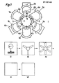
- the complete installation for implementing the method illustrated in FIG. 1 comprises six main work stations, the most important of which are the stacking station I and the crimping station VI.
- the workstations of the installation in the order of the manufacturing process are as follows: The stacking station I, the measuring station II of the height of a partial package, the sheet stacking stations III of thickness D 'less than thickness D and IV for stacking of sheets of thickness D in order to complete the partial package with layers of thickness D 'and / or D depending on the measurement result at station II, the centering station V of segments and setting of rivets and finally the VI crimping station.
- the stacking station I shown quite diagrammatically comprises six magazines 1a and 1b regularly distributed around an adjustment plate 2.
- the annular segments 3 have an angular dimension of 120 * and a thickness D
- the segments 3 represented in phantom lines have been supplied by the stores 1a and brought by the conveyor plates 4a which are represented quite schematically.
- the magazines 1b, offset 60 * from the magazines 1a will provide segments 3 brought by the plates 4b to form one or more layers of segments offset by 60 ° relative to the segments provided by the magazines 1a, in order to allow, d on the one hand, to assemble a package and on the other hand, to compensate for any errors in the nominal value of the thickness of the sheet metal segments.
- the segments of the first layer are brought in, for example, by the plates 4a, and of the following by the plates 4b.
- the segments 3 are held by the retaining members 5 facing the corresponding magazines and transport trays.
- the elements of the stacking station I will be described in more detail using FIGS. 2 to 7a.
- a conveyor device brings a packet of segments of a height H ' ⁇ H, H being the required height, to the measurement station II where the height H' is measured exactly and then the packet passes to stations III and IV comprising, the first, three stores and three transport platforms, and the second, six.
- the magazines of station III are filled with segments of thickness D 'less than D, while those of station IV are filled with segments of thickness D.
- the packet is completed by layers of segments from station III and / or IV. For example, if you have to form a packet of height 21 mm by sheet metal segments of thickness 1 mm, you form at the stacking station I a packet of nineteen layers, you bring the packet at measurement station II to measure its height H 'and then the package goes to stations III and IV where it is completed so that its height is the closest to 21 mm and above all within the required tolerances.
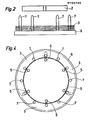
- Figure 2 there is shown a partial side view of the stacking station. There is in particular shown the adjustment plate 2 supporting the holding elements 5, and below, the stacking disc 6 provided with six guide rods 7 regularly distributed on the disc 6. Each of the rings 3 is guided during its fall by two of the rods 7 which engage in two slots spaced 60 °.
- Figure 4 is a top view of Figure 2. There is shown in broken lines in Figure 2 several layers of segments and in Figure 4 we see the upper layer.
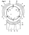
- FIG. 3 we see in solid lines three segments 3 of a ring brought by conveyor plates 4a, only one of which is shown in the lower part of the figure, towards the adjustment plate 2.
- the only carrier plate 4a shown in Figure 3 is mounted on a slide and is driven by a double-acting cylinder. Its end 8 located towards the adjustment plate 2 has the shape of a segment ring dimensions corresponding to those of an annular segment of sheet metal 3, formed in a recess 9 of the plate 4a.
- the recess 9 serves as a stop for an annular segment of sheet metal 3 when it is taken over by the conveyor plate 4a.
- the annular end 8 of a plate 4a or 4b is provided in its middle with a notch 10 of dimensions and shape corresponding to those of the body 5a (which will be described later) of a holding member, 5, projecting radially relative to the adjustment plate 2, in order to allow the transporting plate 4a or 4b to bring the transported segment 3 against the adjustment plate 2.
- the notch 10 is located below a slot 3a limited by two consecutive arms 3b of a ring segment 3.
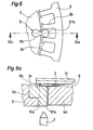
- the outer periphery of a segment is provided with notches 3c used for centering and guiding segments 3 in stores and on the transport trays.
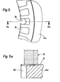
- FIG. 5 represents a partial view of an annular segment 3 supported by a conveyor plate 4a or 4b.
- the notch 10 is visible between two consecutive arms 3b of the segment 3.
- a permanent magnet can be fixed in a housing of the plate to ensure the holding of the segment 3.
- FIG. 5a in dashed lines quite schematically and in cuts a magazine 12 from sheet metal segments 3.
- the conveyor plate moves back until its end having the ring-shaped recess 9 is exactly under the magazine 12, then the lower segment of the stack falls into the recess 9 and the plate 4a is pushed forward towards the adjustment plate 2 (fig. 6,6a, 7,7a) to bring the segment 3 and the cycle begins again.
- FIGs 6 and 6a there is shown a segment 3 near the adjustment plate 2.
- FIG 6 there is shown only part of the adjustment plate 2 with a holding member 5 and a segment 3, the carrier plate was not represented.
- Figure 6a there is shown in section a conveyor plate 4a, the segment 3 the holding member 5, the adjustment plate 2 and an element 13 assisting the holding member 5 which will be described later.
- the holding member 5 has a body 5a projecting relative to the adjustment plate 2 and formed of two parts, a first prismatic part 5'a whose width is less than the peripheral distance between the ends of two consecutive arms 3b of segment 3, and a second cylindrical part 5 "a whose diameter is greater than the distance between the ends of the two consecutive arms 3b and less than the distance between the bodies of said arms.
- This second part 5" a can also be prismatic for as long as its width meets the same conditions as the diameter of the cylindrical part.
- the retaining member 5 is inserted into an approximately cylindrical notch 2a of the adjustment plate 2 by a body 5b of shape and dimensions corresponding to those of the notch 2a of the plate 2.
- the distance between the highest point of the upper face of the part 5 "a and the bearing face of the element 13 must be of the order of 30 to 401 of the thickness of a segment in order to ensure that the segment is properly maintained when the conveyor plate recedes.
- the conveyor plate 4a having arrived at the end of its travel towards the adjustment plate, is subsequently moved in the opposite direction as indicated in FIG. 7a but the segment 3 cannot follow it because the ends of the arms 3b abut against the cylindrical part 5 "a whose diameter is greater than their distance.
- the element 13 moreover ensures the vertical holding of the segment 3 during the retraction of the plate 4a.
- the plate 4a falls vertically on the stacking plate 6 guided by the rods 7. It is obvious that the same operations are carried out simultaneously by the three transport plates 4a (respectively 4b).
- segments alternately magazines 1a and 1b, are brought in by the conveyor plates 4a, respectively 4b.
- the stacking disc 6 is brought to the measurement station II and then to the stations III and IV where operating transport plates and adjustment plates identical to those described.
- the stacking disc 6 is rotated three times by an angle of 120 * .
- the first rotation takes place when the third of the height of the pack is reached, then 2/3 and finally a last time before the evacuation of the pack when H 'is reached.
- the number of rotations can be greater than three, but preferably an integer multiple of three in the present case, and generally speaking, an integer multiple of n, the angle of rotation being a.
- a ring by a greater number of segments, for example six.
- the elements of the installation are the same as those described above with regard to their structure, but the number of magazines of the transport trays and holding members must be adapted to the number of segments constituting a ring.
- the packet After the packet of sheets has passed through stations II, III and IV, the packet arrives at station V, for the installation of rivets.
- the rivets in a single piece of mild steel wire, are introduced into the holes 15 (fig. 3) of the superimposed segments which thus form vertical passages.
- the package Before the establishment of the rivets the package is tightened, between two shells having the shape of a half cylinder in order to ensure an approximate centering of the package.
- the stacking disc is brought to the crimping station VI.
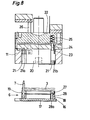
- FIG 8 there is shown a more detailed view of the stacking disc 6 and the crimping device.
- the stacking disc 6 is composed of a plate 16 whose shape is cylindrical or rectangular provided on its underside with two grooves 17 engaging on two corresponding rails of the transfer device.
- a ring 18 crossed by the guide rods 7 (only one of which is shown here), a second removable ring 19 provided with cylindrical passages for the guide rods 7 is suspended on the first ring 18 by small springs (not shown).
- the ring 19 is provided, vertically with the holes 15 of the segments, with cylindrical orifices 27 inside which are spikes whose length is slightly less than that of the orifices 27.
- the spikes are provided at their lower end with a head preventing them from leaving the ring 19 by crossing it from bottom to top.
- Screws 28, regularly distributed, are screwed on the underside of the ring 19.
- the screws 28 pass freely (without being screwed) the ring 18 while their head 28a is housed in a cylindrical passage of the plate 16 located vertically from the either of the grooves 17.
- the crimping device essentially comprises a mold 11, a keel 20 whose role is to center the layers of segments from the inside and from the outside and thus ensure compliance with the inside and outside diameters of the sheet pack found. on the ring 18 before crimping, the mold and the keel being subjected to a press 22. Between the mold 11 and the keel 20 is the stripper 21 shown here in two extreme positions, low position to the right of FIG. 8 and upper left position of the same figure. Crimping is carried out in the following manner: the press 22 lowers the mold 11 and the keel 20 on the sheet pack 3 supported by the stacking disc 6 described above.
- the stripper 21 in the low position comes into contact with the package and as the press descends, the mold 11 and the keel 20 center the successive layers of sheets, the stripper being provided with a series of orifices 21a for the passage of guide rods 7 and a series of orifices 21b for the passage of rivets and crimping points 23.
- the outside diameter of the keel 20 and the inside diameter of the mold 11 correspond exactly to the inside diameter, respectively exterior, of the chosen package of sheets.
- the upper heads are obtained by the action of the tips 23 and the lower heads by the tips housed in the cylindrical orifices 27 of the ring 19 of the stacking disc 6.
- the press rises and the package is expelled by the descent of the stripper 21 under the action of a vertical force exerted by rods 26 driven by a jack.
- the depositor has manufactured bundles of sheets with a nominal height of 21 mm by obtaining bundles whose lack of parallelism between the two faces of the bundle is 0.15 mm while for bundles formed with closed rings this defect is at least 0.4 mm.
- the assembly of the sheet packs can be done in another way, for example by welding, but before this, it is absolutely necessary to center the sheet pack with a device as described above, provided with a mold and a keel.
Landscapes
- Engineering & Computer Science (AREA)
- Manufacturing & Machinery (AREA)
- Power Engineering (AREA)
- Sheets, Magazines, And Separation Thereof (AREA)
- Manufacture Of Motors, Generators (AREA)
- Manufacturing Cores, Coils, And Magnets (AREA)
- Stacking Of Articles And Auxiliary Devices (AREA)
- Organic Low-Molecular-Weight Compounds And Preparation Thereof (AREA)
Applications Claiming Priority (2)
| Application Number | Priority Date | Filing Date | Title |
|---|---|---|---|
| FR8313104 | 1983-08-09 | ||
| FR8313104A FR2550478B1 (fr) | 1983-08-09 | 1983-08-09 | Procede de fabrication de paquets de toles magnetiques ou autres de forme annulaire et installation de mise en oeuvre |
Publications (3)
| Publication Number | Publication Date |
|---|---|
| EP0136740A1 true EP0136740A1 (de) | 1985-04-10 |
| EP0136740B1 EP0136740B1 (de) | 1987-10-14 |
| EP0136740B2 EP0136740B2 (de) | 1991-09-18 |
Family
ID=9291516
Family Applications (1)
| Application Number | Title | Priority Date | Filing Date |
|---|---|---|---|
| EP84201144A Expired - Lifetime EP0136740B2 (de) | 1983-08-09 | 1984-08-06 | Verfahren zur Herstellung von Paketen ringförmiger, magnetischer oder anderer Bleche und Anlage zu dessen Durchführung |
Country Status (6)
| Country | Link |
|---|---|
| US (1) | US4597172A (de) |
| EP (1) | EP0136740B2 (de) |
| CA (1) | CA1229721A (de) |
| DE (1) | DE3466841D1 (de) |
| ES (1) | ES8406247A1 (de) |
| FR (1) | FR2550478B1 (de) |
Cited By (5)
| Publication number | Priority date | Publication date | Assignee | Title |
|---|---|---|---|---|
| FR2612703A1 (fr) * | 1987-03-18 | 1988-09-23 | Ducellier & Cie | Procede de realisation de stator d'alternateur et alternateur ainsi obtenu |
| FR2631755A1 (fr) * | 1988-03-02 | 1989-11-24 | Emiliane Trancerie Spa | Procede pour la realisation d'un circuit magnetique de stator de machines electriques rotatives ou d'un circuit magnetique de transformateurs, et circuit magnetique ainsi obtenu |
| FR2641909A1 (fr) * | 1989-01-19 | 1990-07-20 | Capemmo Umberto | Procede de fabrication de cage, ou stator de machine dynamo-electrique, et cage obtenue selon le procede |
| RU2172051C1 (ru) * | 2000-12-15 | 2001-08-10 | ООО "КД-Электро" | Способ изготовления ротора электрической машины |
| US6634080B2 (en) | 2000-03-21 | 2003-10-21 | Schuler Pressen Gmbh & Co. Kg | Method for producing parcels consisting of sheet metal pieces |
Families Citing this family (13)
| Publication number | Priority date | Publication date | Assignee | Title |
|---|---|---|---|---|
| ATE70385T1 (de) * | 1986-05-22 | 1991-12-15 | Steinemann Ulrich Ag | Verfahren und vorrichtung zum schichten von blechpaketen, insbesondere von transformatorenkernen. |
| US4882832A (en) * | 1987-02-02 | 1989-11-28 | Emerson Electric Co. | Method of manufacturing electric motor stator structure |
| US4918831A (en) * | 1987-12-28 | 1990-04-24 | General Electric Company | Method of fabricating composite rotor laminations for use in reluctance, homopolar and permanent magnet machines |
| US5098276A (en) * | 1989-06-01 | 1992-03-24 | Westinghouse Electric Corp. | Apparatus for making a superconducting magnet for particle accelerators |
| US5072516A (en) * | 1989-06-01 | 1991-12-17 | Westinghouse Electric Corp. | Apparatus and process for making a superconducting magnet for particle accelerators |
| US5088184A (en) * | 1989-06-01 | 1992-02-18 | Westinghouse Electric Corp. | Process for making a superconducting magnet for particle accelerators |
| US5065496A (en) * | 1989-06-01 | 1991-11-19 | Westinghouse Electric Corp. | Process for making a superconducting magnet coil assembly for particle accelerators |
| US5065497A (en) * | 1989-06-01 | 1991-11-19 | Westinghouse Electric Corp. | Apparatus for making a superconducting magnet for particle accelerators |
| FR2800933B1 (fr) * | 1999-11-10 | 2001-12-28 | Bourgeois R | Procede de fabrication de paquets de toles de forme annulaire |
| US6484388B1 (en) * | 2000-08-10 | 2002-11-26 | Delphi Technologies, Inc. | Sequential roll-forming process for a stator |
| DE102004008567B4 (de) * | 2004-02-19 | 2013-08-01 | Volkswagen Ag | Vorrichtung und Verfahren zum Herstellen eines in einer Ebene mehrere Segmente aufweisenden ringförmigen Bauteils |
| CN111036780B (zh) * | 2020-01-08 | 2024-06-14 | 承盛航空测试科技(苏州)有限公司 | 一种微型探针自动打点铆合机 |
| CN119839130A (zh) * | 2025-03-10 | 2025-04-18 | 青岛盛裕精密模具有限公司 | 一种电机定子冲压模具 |
Citations (5)
| Publication number | Priority date | Publication date | Assignee | Title |
|---|---|---|---|---|
| FR1335212A (fr) * | 1962-07-26 | 1963-08-16 | Philips Nv | Dispositif pour la fabrication de paquets faits de plaquettes métalliques planes identiques, percées d'au moins un trou, notamment pour stators ou rotors |
| GB1110594A (en) * | 1965-05-21 | 1968-04-18 | Elmasch Bau Sachsenwerk Dresde | Process and apparatus for production of stator and rotor plates for electrical machines |
| DE2631188A1 (de) * | 1976-07-10 | 1978-01-19 | Schuler Gmbh L | Steuerschaltung fuer eine nutenstanzanlage |
| FR2487597A1 (fr) * | 1980-07-24 | 1982-01-29 | Weingarten Ag Maschf | Dispositif de mise en paquets pour toles dynamo de grand diametre subdivisees en segments de couronne pour la fabrication d'anneaux de generatrices (rotor et stator) |
| EP0084568A1 (de) * | 1981-03-31 | 1983-08-03 | Matsushita Electric Industrial Co., Ltd. | Herstellungsvorrichtung für ein laminat mit eisenkern |
Family Cites Families (4)
| Publication number | Priority date | Publication date | Assignee | Title |
|---|---|---|---|---|
| US3573129A (en) * | 1969-02-13 | 1971-03-30 | Emerson Electric Co | Stator core assembling apparatus |
| DE2629532A1 (de) * | 1975-07-03 | 1977-01-27 | Sev Alternateurs | Verfahren und vorrichtung fuer einen stator oder rotor einer elektrischen rotationsmaschine |
| US4080724A (en) * | 1976-01-13 | 1978-03-28 | Zephyr Wind Dynamo Company | Method of forming electrical machine care from E-laminations |
| US4079512A (en) * | 1976-06-03 | 1978-03-21 | Lakes Lee J | Core lamination selecting apparatus |
-
1983
- 1983-08-09 FR FR8313104A patent/FR2550478B1/fr not_active Expired
- 1983-12-07 ES ES527899A patent/ES8406247A1/es not_active Expired
-
1984
- 1984-07-30 US US06/635,421 patent/US4597172A/en not_active Expired - Lifetime
- 1984-07-31 CA CA000460118A patent/CA1229721A/en not_active Expired
- 1984-08-06 EP EP84201144A patent/EP0136740B2/de not_active Expired - Lifetime
- 1984-08-06 DE DE8484201144T patent/DE3466841D1/de not_active Expired
Patent Citations (5)
| Publication number | Priority date | Publication date | Assignee | Title |
|---|---|---|---|---|
| FR1335212A (fr) * | 1962-07-26 | 1963-08-16 | Philips Nv | Dispositif pour la fabrication de paquets faits de plaquettes métalliques planes identiques, percées d'au moins un trou, notamment pour stators ou rotors |
| GB1110594A (en) * | 1965-05-21 | 1968-04-18 | Elmasch Bau Sachsenwerk Dresde | Process and apparatus for production of stator and rotor plates for electrical machines |
| DE2631188A1 (de) * | 1976-07-10 | 1978-01-19 | Schuler Gmbh L | Steuerschaltung fuer eine nutenstanzanlage |
| FR2487597A1 (fr) * | 1980-07-24 | 1982-01-29 | Weingarten Ag Maschf | Dispositif de mise en paquets pour toles dynamo de grand diametre subdivisees en segments de couronne pour la fabrication d'anneaux de generatrices (rotor et stator) |
| EP0084568A1 (de) * | 1981-03-31 | 1983-08-03 | Matsushita Electric Industrial Co., Ltd. | Herstellungsvorrichtung für ein laminat mit eisenkern |
Non-Patent Citations (1)
| Title |
|---|
| PATENTS ABSTRACTS OF JAPAN, vol. 2, no. 96, 11 août 1978, page 4636E78; & JP - A - 53 61009 (TOKYO SHIBAURA DENKI K.K.) 01-06-1978 * |
Cited By (5)
| Publication number | Priority date | Publication date | Assignee | Title |
|---|---|---|---|---|
| FR2612703A1 (fr) * | 1987-03-18 | 1988-09-23 | Ducellier & Cie | Procede de realisation de stator d'alternateur et alternateur ainsi obtenu |
| FR2631755A1 (fr) * | 1988-03-02 | 1989-11-24 | Emiliane Trancerie Spa | Procede pour la realisation d'un circuit magnetique de stator de machines electriques rotatives ou d'un circuit magnetique de transformateurs, et circuit magnetique ainsi obtenu |
| FR2641909A1 (fr) * | 1989-01-19 | 1990-07-20 | Capemmo Umberto | Procede de fabrication de cage, ou stator de machine dynamo-electrique, et cage obtenue selon le procede |
| US6634080B2 (en) | 2000-03-21 | 2003-10-21 | Schuler Pressen Gmbh & Co. Kg | Method for producing parcels consisting of sheet metal pieces |
| RU2172051C1 (ru) * | 2000-12-15 | 2001-08-10 | ООО "КД-Электро" | Способ изготовления ротора электрической машины |
Also Published As
| Publication number | Publication date |
|---|---|
| US4597172A (en) | 1986-07-01 |
| EP0136740B2 (de) | 1991-09-18 |
| DE3466841D1 (en) | 1987-11-19 |
| ES527899A0 (es) | 1984-08-01 |
| CA1229721A (en) | 1987-12-01 |
| FR2550478B1 (fr) | 1986-05-23 |
| ES8406247A1 (es) | 1984-08-01 |
| EP0136740B1 (de) | 1987-10-14 |
| FR2550478A1 (fr) | 1985-02-15 |
Similar Documents
| Publication | Publication Date | Title |
|---|---|---|
| EP0136740B1 (de) | Verfahren zur Herstellung von Paketen ringförmiger, magnetischer oder anderer Bleche und Anlage zu dessen Durchführung | |
| EP2758327B1 (de) | Vorrichtung zur übertragung vorgeformter schichten von objekten auf das obere ende einer palette | |
| EP2619118B1 (de) | Vorrichtung für den transport von bündeln für eine umreifungsmaschine | |
| CH686509A5 (fr) | Dispositif empileur-retourneur pour machine dite imprimeuse-decoupeuse de production de boîtes d'emballage. | |
| EP4234457A2 (de) | Palettengreifer | |
| FR2989012A1 (fr) | Changeur d'electrodes | |
| FR2928636A1 (fr) | Dispositif et procede de preparation de mandrins, dispositif de recueil des mandrins bobine et dispositif et procede de manutention des mandrins | |
| FR2475817A1 (fr) | Dispositif d'insertion de bobines pre-enroulees dans les encoches de stators | |
| EP1100185B1 (de) | Verfahren zum Herstellen eines ringförmigen Blechpaketes | |
| EP1335480B1 (de) | Verfahren und Vorrichtung zur Herstellung eines magnetischen Kreises einer elektrischen Maschine | |
| EP3526025A1 (de) | Vorrichtung und verfahren zur entfernung eines kastens von einem spannfutter | |
| EP1559183A1 (de) | Verfahren und vorrichtung zum einziehen von spulen in ein statorblechpaket mit stratifikatwicklung | |
| WO2016009137A1 (fr) | Procede de realisation d'un stator bobine de machine electrique tournante | |
| FR3057201A1 (fr) | Procede et dispositif de mise en forme d’un flan autour d’un mandrin. | |
| CH625724A5 (de) | ||
| CH658609A5 (en) | Machine for punching sheet metal | |
| FR2538971A1 (fr) | Procede et outil centreur pour inserer des entre-phases isolants dans les encoches de stators pour machines electriques | |
| EP0040576A1 (de) | Verfahren und Förderanlage für längliche Gegenstände, insbesondere für Rohre | |
| EP4393049B1 (de) | Verfahren und anordnung zur montage von leitenden haarnadelwicklungen für eine elektrische drehmaschine | |
| EP0236213A1 (de) | Automatisches Verfahren zur Herstellung von Spulen ohne Stützgestell und zum Anbringen derselben auf eine Leiterplatte und Maschine zur Ausführung | |
| BE1010305A3 (fr) | Outil inferieur d'un separateur de poses dans une machine de travail d'elements en plaques ou en feuilles. | |
| EP2414244B1 (de) | Anlage und verfahren zum verpacken von komponenten in form von streifen | |
| FR3102077A1 (fr) | Dispositif d'alimentation en plaques d'une machine de decoupe a partir d'un magasin. | |
| EP4393051A1 (de) | Verfahren und anordnung zur montage leitfähiger stifte für eine elektrische drehmaschine | |
| FR2612703A1 (fr) | Procede de realisation de stator d'alternateur et alternateur ainsi obtenu |
Legal Events
| Date | Code | Title | Description |
|---|---|---|---|
| PUAI | Public reference made under article 153(3) epc to a published international application that has entered the european phase |
Free format text: ORIGINAL CODE: 0009012 |
|
| AK | Designated contracting states |
Designated state(s): CH DE FR GB IT LI |
|
| 17P | Request for examination filed |
Effective date: 19850603 |
|
| 17Q | First examination report despatched |
Effective date: 19860711 |
|
| GRAA | (expected) grant |
Free format text: ORIGINAL CODE: 0009210 |
|
| ITF | It: translation for a ep patent filed | ||
| AK | Designated contracting states |
Kind code of ref document: B1 Designated state(s): CH DE FR GB IT LI |
|
| REF | Corresponds to: |
Ref document number: 3466841 Country of ref document: DE Date of ref document: 19871119 |
|
| GBT | Gb: translation of ep patent filed (gb section 77(6)(a)/1977) | ||
| PLBI | Opposition filed |
Free format text: ORIGINAL CODE: 0009260 |
|
| PLAB | Opposition data, opponent's data or that of the opponent's representative modified |
Free format text: ORIGINAL CODE: 0009299OPPO |
|
| 26 | Opposition filed |
Opponent name: KIENLE & SPIESS STANZ- UND DRUCKGIEBWERK GMBH Effective date: 19880714 |
|
| R26 | Opposition filed (corrected) |
Opponent name: KIENLE & SPIESS STANZ- UND DRUCKGIEBWERK GMBH Effective date: 19880811 |
|
| PUAH | Patent maintained in amended form |
Free format text: ORIGINAL CODE: 0009272 |
|
| STAA | Information on the status of an ep patent application or granted ep patent |
Free format text: STATUS: PATENT MAINTAINED AS AMENDED |
|
| ITTA | It: last paid annual fee | ||
| 27A | Patent maintained in amended form |
Effective date: 19910918 |
|
| AK | Designated contracting states |
Kind code of ref document: B2 Designated state(s): CH DE FR GB IT LI |
|
| ITF | It: translation for a ep patent filed | ||
| GBTA | Gb: translation of amended ep patent filed (gb section 77(6)(b)/1977) | ||
| REG | Reference to a national code |
Ref country code: GB Ref legal event code: IF02 |
|
| PGFP | Annual fee paid to national office [announced via postgrant information from national office to epo] |
Ref country code: DE Payment date: 20030618 Year of fee payment: 20 |
|
| PGFP | Annual fee paid to national office [announced via postgrant information from national office to epo] |
Ref country code: FR Payment date: 20030620 Year of fee payment: 20 |
|
| PGFP | Annual fee paid to national office [announced via postgrant information from national office to epo] |
Ref country code: GB Payment date: 20030806 Year of fee payment: 20 |
|
| PGFP | Annual fee paid to national office [announced via postgrant information from national office to epo] |
Ref country code: CH Payment date: 20030808 Year of fee payment: 20 |
|
| PG25 | Lapsed in a contracting state [announced via postgrant information from national office to epo] |
Ref country code: LI Free format text: LAPSE BECAUSE OF EXPIRATION OF PROTECTION Effective date: 20040805 Ref country code: GB Free format text: LAPSE BECAUSE OF EXPIRATION OF PROTECTION Effective date: 20040805 Ref country code: CH Free format text: LAPSE BECAUSE OF EXPIRATION OF PROTECTION Effective date: 20040805 |
|
| REG | Reference to a national code |
Ref country code: GB Ref legal event code: PE20 |
|
| REG | Reference to a national code |
Ref country code: CH Ref legal event code: PL |