EP4234457A2 - Palettengreifer - Google Patents
Palettengreifer Download PDFInfo
- Publication number
- EP4234457A2 EP4234457A2 EP23179205.2A EP23179205A EP4234457A2 EP 4234457 A2 EP4234457 A2 EP 4234457A2 EP 23179205 A EP23179205 A EP 23179205A EP 4234457 A2 EP4234457 A2 EP 4234457A2
- Authority
- EP
- European Patent Office
- Prior art keywords
- pallet
- tool
- gripper
- gripping
- hand
- Prior art date
- Legal status (The legal status is an assumption and is not a legal conclusion. Google has not performed a legal analysis and makes no representation as to the accuracy of the status listed.)
- Granted
Links
Images

Classifications
-
- B—PERFORMING OPERATIONS; TRANSPORTING
- B65—CONVEYING; PACKING; STORING; HANDLING THIN OR FILAMENTARY MATERIAL
- B65G—TRANSPORT OR STORAGE DEVICES, e.g. CONVEYORS FOR LOADING OR TIPPING, SHOP CONVEYOR SYSTEMS OR PNEUMATIC TUBE CONVEYORS
- B65G47/00—Article or material-handling devices associated with conveyors; Methods employing such devices
- B65G47/74—Feeding, transfer, or discharging devices of particular kinds or types
- B65G47/90—Devices for picking-up and depositing articles or materials
- B65G47/902—Devices for picking-up and depositing articles or materials provided with drive systems incorporating rotary and rectilinear movements
-
- B—PERFORMING OPERATIONS; TRANSPORTING
- B65—CONVEYING; PACKING; STORING; HANDLING THIN OR FILAMENTARY MATERIAL
- B65G—TRANSPORT OR STORAGE DEVICES, e.g. CONVEYORS FOR LOADING OR TIPPING, SHOP CONVEYOR SYSTEMS OR PNEUMATIC TUBE CONVEYORS
- B65G49/00—Conveying systems characterised by their application for specified purposes not otherwise provided for
- B65G49/05—Conveying systems characterised by their application for specified purposes not otherwise provided for for fragile or damageable materials or articles
- B65G49/06—Conveying systems characterised by their application for specified purposes not otherwise provided for for fragile or damageable materials or articles for fragile sheets, e.g. glass
- B65G49/068—Stacking or destacking devices; Means for preventing damage to stacked sheets, e.g. spaces
- B65G49/069—Means for avoiding damage to stacked plate glass, e.g. by interposing paper or powder spacers in the stack
-
- B—PERFORMING OPERATIONS; TRANSPORTING
- B66—HOISTING; LIFTING; HAULING
- B66F—HOISTING, LIFTING, HAULING OR PUSHING, NOT OTHERWISE PROVIDED FOR, e.g. DEVICES WHICH APPLY A LIFTING OR PUSHING FORCE DIRECTLY TO THE SURFACE OF A LOAD
- B66F9/00—Devices for lifting or lowering bulky or heavy goods for loading or unloading purposes
- B66F9/06—Devices for lifting or lowering bulky or heavy goods for loading or unloading purposes movable, with their loads, on wheels or the like, e.g. fork-lift trucks
- B66F9/075—Constructional features or details
- B66F9/12—Platforms; Forks; Other load supporting or gripping members
- B66F9/18—Load gripping or retaining means
-
- B—PERFORMING OPERATIONS; TRANSPORTING
- B65—CONVEYING; PACKING; STORING; HANDLING THIN OR FILAMENTARY MATERIAL
- B65G—TRANSPORT OR STORAGE DEVICES, e.g. CONVEYORS FOR LOADING OR TIPPING, SHOP CONVEYOR SYSTEMS OR PNEUMATIC TUBE CONVEYORS
- B65G2201/00—Indexing codes relating to handling devices, e.g. conveyors, characterised by the type of product or load being conveyed or handled
- B65G2201/02—Articles
- B65G2201/0267—Pallets
-
- B—PERFORMING OPERATIONS; TRANSPORTING
- B65—CONVEYING; PACKING; STORING; HANDLING THIN OR FILAMENTARY MATERIAL
- B65G—TRANSPORT OR STORAGE DEVICES, e.g. CONVEYORS FOR LOADING OR TIPPING, SHOP CONVEYOR SYSTEMS OR PNEUMATIC TUBE CONVEYORS
- B65G2249/00—Aspects relating to conveying systems for the manufacture of fragile sheets
- B65G2249/04—Arrangements of vacuum systems or suction cups
-
- B—PERFORMING OPERATIONS; TRANSPORTING
- B65—CONVEYING; PACKING; STORING; HANDLING THIN OR FILAMENTARY MATERIAL
- B65G—TRANSPORT OR STORAGE DEVICES, e.g. CONVEYORS FOR LOADING OR TIPPING, SHOP CONVEYOR SYSTEMS OR PNEUMATIC TUBE CONVEYORS
- B65G2249/00—Aspects relating to conveying systems for the manufacture of fragile sheets
- B65G2249/04—Arrangements of vacuum systems or suction cups
- B65G2249/045—Details of suction cups suction cups
Definitions
- the present invention relates to the field of equipment for the transfer of products from or to a pallet, and relates, on the one hand, to a particular gripping tool as well as a robotic device comprising such a tool, and, on the other hand, a method implementing this device.
- a conventional robotic transfer device is then able to process, on the one hand, the transfer of the products from or to the pallet, and, on the other hand, the transfer of the pallet, from or to the product transfer zone.
- a transfer device thus rests on a tool, gripping head type, provided with means for gripping products. Generally, each product is selected individually. To successfully transfer an empty pallet, the same tool is then sometimes also provided with a pallet gripping means.
- a principle then known for example by JP2001122437 , FR2723732 , or FR2558811 is based on the provision, at this tooling, of arms in the form of hooks, retractable by rotation in said tooling.
- a pair of hooks faces a second pair of hooks, and the gripped pallet rests on the end of these hooks. The hooks thus support the empty pallet, fitting into two sides of the pallet facing each other.
- pairs of arms must be sufficiently spaced from each other to receive between them a pallet, which obviously results either in a significant wheelbase of the tooling on which they are mounted, either by a complex retraction system for mobile tools.
- this tool being moved by a robot or other manipulator, its weight has direct consequences on the dimensioning required for said robot to reach the desired rates and the corresponding accelerations.
- the gripping means are a source of mass to be improved.
- the invention proposes to grasp the empty pallet from just one of its edges, holding it cantilevered rather than supporting it from two spaced apart places between which the center of gravity of the pallet is located. This thus makes it possible to use a gripping solution without vis-à-vis.
- the invention thus relates to a tool to be mounted on a manipulator and capable of gripping flat pallet-type bases, said tool comprising a frame, as well as a gripper for said bases, mounted on said frame.
- This tool is characterized in that the gripper is movable in the frame to cooperate with a single edge of a pallet.
- the invention also relates to a complete transfer device for moving pallets, namely a robotic transfer device comprising, on the one hand, a multi-axis manipulator, and, on the other hand, mounted on it to move it, a tool as described above.
- This method is characterized in that picking up the pallet essentially consists in taking it cantilevered, from one of its edges.
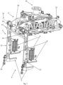
- the invention therefore firstly relates to a tool 1, to be mounted on a manipulator 2 and capable of gripping flat pallet-type bases 3, said tool 1 comprising a frame 4, as well as a gripper 5 for said bases, mounted on said frame 4.
- the tool 1 is also capable of gripping products.
- the characteristics described apply both to a tool 1 capable of gripping products and to a tool lacking this capacity.
- the tool 1 thus serves, on the one hand, to pick up and transfer products, and, on the other hand, to pick up and transfer bases or pallets 3.
- the products are generally stored in the form of a plurality creating a layer, and several layers being superimposed on the base or pallet 3.
- the tool 1 transfers an empty pallet 3 to the palletization zone, then the products to be palletized.
- the tool 1 transfers the products from the depalletization zone where the full pallet 3 is located, then transfers the empty pallet 3.
- a spacer in the form of a sheet, for example cardboard, laminated or otherwise, is sometimes used to separate two successive layers of products on the pallet 3.
- the tool 1 can then also be responsible for transferring this spacer, again either to the palletization area or from the depalletization area.
- the tool 1 is mounted at the mobile end of a manipulator 2 so that it can be moved in its work zone, which covers in particular the palletizing or depalletizing zone, as well as, in the case where it is also used for picking up and transferring products, the zone for picking up or depositing products, as well as the zone for picking up or depositing the pallet 3, or even also the spacer.
- the frame 4 allows the mounting of the tool 1 on the manipulator 2 and the fixing of the functional elements.
- the gripper 5 is movable in the frame 4 to cooperate with a single edge of a pallet 3, in particular being movable from one side of said frame 4.
- the gripper 5 forms the part of the tool 1 which serves to process 3 pallets or bases. It is retractable and therefore has two different positions, namely a working position and a retracted position. In the working position, when the tool 1 is capable of seizing products in addition to the pallets, it can reach a surface beyond that where the products are retained in the tool 1. It is therefore necessary to retract so that it does not interfere with the function of the tool 1 when working to enter the products themselves.
- the base or pallet 3 When taken by the tool 1, the base or pallet 3 is essentially horizontal. At this moment, the gripper 5 essentially extends in a vertical plane in its working position. With the same position of the tool 1 in space, the gripper 5 extends essentially horizontally once in the retracted position.
- the gripper 5 therefore grips the base or pallet 3 at only one of its edges, the pallet 3 therefore being held by the tool 1 cantilevered from the gripper 5, and possibly asymmetrical with respect to the tool 1 himself.
- the pallet 3 has in fact a generally rectangular shape, generally not square, and thus has four edges. To transfer the pallet 3, the proposed tool 1 therefore grasps it only by one of its edges and not simultaneously at opposite edges. The gripper 5 is thus more compact than in a solution gripping the pallet 3 symmetrically. The tool 1 is thus lighter and the manipulator 2 can be less powerful, and housing the gripper 5 in the tool 1 in the retracted position is easier and more compact in terms of design.
- the gripper 5 is mobile and essentially extends from one side of the tool 1 in the working position.
- the gripper 5 is rotatable at the level of an axis of rotation 12 which is located along one side of the tool 1.
- the gripper 5 comprises a clamping means 6 forming a vice to grip the edge of a pallet 3 so as to hold it cantilevered.
- the clamping means 6 forming a vice thus has two jaws facing each other, and which approach with the pallet 3 between them, with the aim of grasping it firmly, then moving away from each other to release and release it.
- the gripper 5 therefore not only provides support from below the pallet 3.
- the pallet 3 is clamped between the jaws of the clamping means 6 to be anchored in the tool 1 and stationary relative to it.
- the clamping means 6 therefore acts on a sufficiently large surface of the pallet 3 to exert the required force.
- the clamping means 6 has, on the one hand, a support 7 for the pallet 3, in particular to be inserted into the pallet 3, and, on the other hand, a sole 8, to come into vis-à-vis the support 7, so that the pallet 3 is caught between the support 7 and the sole 8 together forming a vice, and this with all its thickness or only a part.
- the pallet 3 in fact has openings in its sides, with the aim of allowing the insertion of forks of a forklift. It is thus possible to insert one of the two jaws described above of the clamping means 6 of the gripper 5 into these side openings. The other jaw is beyond the product receiving surface presented by pallet 3.
- the pallet 3 defines an upper surface, on which products can be received, and a lower surface, at which it comes into contact with a plane on which it is located.
- One of the jaws, preferably the support 7, can then optionally come between these surfaces.
- the two jaws can each be located beyond these surfaces, outside the template defined between them.
- the pallet 3 sometimes being made of a superposition of wooden planks, the clamping means 6 can grasp only part of this superposition.
- the support 7 has a length of between 10 and 18 centimeters, preferably around 12.5 centimeters.
- the support 7, which forms the lower element of the clamping means 6, can be inserted from the edge of the pallet 3 up to approximately between 10 and 18 centimeters, preferably approximately 12.5 centimeters.
- the support 7 has a length comprised in the range going from 2 to 50%, in particular from 3 to 30%, preferably, from 5 to 20% of the dimension of the pallet 3 which is located along the support. 7 when inserted into the pallet.
- the support 7 can be formed of several surfaces spaced apart from each other, each intended to come to a predefined position in the edge of the pallet 3.
- the figure 1 indeed shows a support 7 in the form of two different surfaces, carried by the free and curved ends of the gripper 5, and spaced apart from each other.
- the sole 8 is also formed by two different surfaces, arriving in front of the two support surfaces 7. Any configuration is possible to produce a clamping means 6 with a sufficient working surface to clamp the pallet 3 and hold it door to door. fake.
- the sole 8 is movable in the gripper 5 to approach the support 7 and thus grip the pallet 3 or to move away from it and thus release the pallet 2, the gripper 5 being provided, in addition, on the one hand, an actuator 9 acting on the sole 8, and, on the other hand, a separate linear guide 10 for the movement of said sole 8 in the gripper 5.
- the actuator 9 acts as the element ensuring the clamping force of the clamping means 6. It is coupled with a guide 10, in order to prevent the torsional force generated by the pallet 3 held cantilevered from being fully compensated by the actuator 9 itself.
- the gripper 5 of the pallet 3 is therefore provided, on the one hand, with a clamping means 6 acting under the effect of an actuator 9 to firmly clamp the pallet 3, and, on the other hand, with a means dedicated to absorbing the torque generated by maintaining the pallet 3 cantilevered.
- the gripper 5 has two arms 11 spaced apart from each other, the ends of which each form a surface of the support 7, and which each carry a sole 8 mounted, on the one hand , on an actuator 9 for applying the required clamping force, and, on the other hand, on a guide 10 to guarantee its position.
- the sole 8 and the support 7 carry a flat surface which comes against the pallet 3.
- the actuator 9 and the guide 10 are fixed to the arms 11 of the gripper 5.
- the guide 10 and the actuator 9 are preferably located, with respect to the jaws of the vice formed by the sole 8 and the support 7, on the side of the frame 4. Thus, the guide 10 and the actuator 9 are located between the frame 4 and pallet 3 entered.
- the gripper 5 has a plurality of arms 11 integral in rotation in the tool 1 around an axis of rotation 12 located at one edge of the tool 1, said arms 11 each having, at their free end, a gripper to together form the clamping means 6.
- the arms 11 are preferably integral because they are mounted on the ends of the same shaft 16.
- Said gripper thus has a first jaw and a second jaw, intended to come above the first in the pallet gripping position 3, the support 7 being in particular formed from the plurality of first jaws, the sole 8 being formed from the plurality of second bit.
- the tool 1 has, on the one hand, at least one retractable lever 13, movably mounted on the frame 4 at the level of the side opposite to that where the gripper 5 is mounted, and, d on the other hand, a plurality of suction cups 14, for gripping an insert, at least one of them being mounted on the gripper 5 and at least one other being mounted on said at least one lever 13.
- the tool 1 has two such levers 13, each on one side of the tool 1.
- the tool 1 thus has two U-shaped structures, one dedicated to suction cups 14 located at its end, the the other carrying both the gripper 5 and its clamping means 6 and other suction cups 14.
- the two U-shaped structures face each other and are movable independently of each other, rotating around parallel axes, each located at an edge of the tool 1.
- Each of the two structures has two positions, one retracted where it does not interfere with the taking of products by the tool 1 when the latter is also dedicated to the taking and transfer of products, and one of work, in which it extends cantilevered from frame 4.
- the U-shaped structure carrying only the suction cups 14 is in the working position only when gripping an insert, while the U-shaped structure forming the gripper is in the working position, on the one hand, for enter a pallet 3, and, on the other hand, to enter a spacer.
- the structure carrying only the suction cups 14 is therefore normally in the working position only when the other U-shaped structure is also.
- Each U-shaped structure is set in motion using an eccentric provided on the central core of the U, and at the end of which acts a jack-type actuator.
- the retracted or extended position of this cylinder therefore defines the state of the corresponding structure, either in the retracted position, parallel to the bottom of the tool 1, or either in the working position, extending parallel to the bottom of the tool 1.
- the tool 1 also has, mounted on the frame 4, abutment surfaces 17 against which the gripper 5 is pressed in the active position, and positioned so as to contribute to absorbing the force created by the weight of the pallet 3. Under the effect of the weight of the pallet 3, the gripper 5 is pressed against these abutment surfaces, which stabilizes it in position.
- the invention also relates to a device in which this tool 1 is mounted, to transfer pallets 3, or even spacers, in the form of flat elements, generally cardboard or plastic coated.
- this tool 1 is mounted, to transfer pallets 3, or even spacers, in the form of flat elements, generally cardboard or plastic coated.
- a robotic transfer device comprising, on the one hand, a multi-axis manipulator 2, and, on the other hand, mounted on it to move it, a tool 1 as described above.
- the robotic device may comprise in particular, in addition, means for grasping at least one product, of the bottle, box or other type, which must then be deposited or picked up by the tool 1 on or above a pallet 3 , the products being preferably organized on the pallet 3 in superimposed layers of several products next to each other.
- a product gripping means can be at the level of the tool 1, in the form of a set of suction cups, of the tulip type, which each grip a product, or even two flanks which face each other and between which at least one product can come be taken.
- the gripper 5 must be retracted into the tool 1 in particular so as not to interfere with the gripping of products by it when it is suitable for this. It therefore goes into the working position on the occasion of the transfer of a pallet 3 or a spacer.
- taking the pallet 3 essentially consists in taking it cantilevered, from one of its edges. A force is therefore exerted on the pallet 3 also from its upper part, and not only from its lower part. The pallet 3 is then firmly held in the tool 1, which therefore drives it in its movement, the latter being caused by the manipulator 2 at the end of which it is mounted. The pallet 3 is therefore held tight in position in the tool 1 at one of its edges only.
- the gripping of the pallet 3 is done by pinching it at the gripping edge, that is to say at its edge at the level of which the palette 3 is held by the tool 1.
- This gripping by pinching is done in particular between two jaws gripping part of the thickness of the pallet 3, or even between two jaws gripping at least one board constituting the pallet 3.
- the pallet 3 is taken asymmetrical with respect to the tool 1, so that, seen perpendicular to the pallet 3 taken, its center of symmetry is offset from that of the tool 1.
- the center of gravity of the pallet 3 is not located in line with the plate 15, the latter being normally positioned centered in the tool 1.
- the gripper 5 is such that its active position does not depend on the size of the pallet 3 to be processed , which of course considerably simplifies the tool 1 and therefore reduces its weight.
- Pallet 3 extends essentially from an edge of frame 4, from which gripper 5 extends in the active position.
- the gripping of the pallet 3 is done by lifting the pallet 3 using a first jaw inserted beforehand, to shift the pallet 3 from its base at the level of the gripping edge, then by tightening against it a second jaw, the pallet 3 being taken between them.
- the pallet 3 is therefore offset from its support surface at the level of its edge where it is taken by the gripper 5, and this before being effectively clamped by the force exerted by the counter jaw for a firm hold in the tooling 1. Tightening the edge of the pallet 3 can have the effect of lifting the opposite edge and then taking it off entirely from the surface on which it is located. Lifting the other edge can also be done after clamping the pallet 3, then moving the tool 1.
- the tool 1 has a structural frame 4 which makes it possible to fix the various elements of the tool 1 and to anchor it to the manipulator 2, possibly with at least one degree of freedom.
- the tool 1 is intended to be mounted at the end of a manipulator 2 which is preferably a multi-axis robot.
- the tool 1 therefore has, in an upper part, a plate 15 for fixing the tool 1 to the manipulator 2.
- the movement of the manipulator 2 makes it possible to move the tool 1 in the work zone, which may comprise a stack of products, above a pallet 3, these products being either to be deposited on the pallet 3 or to be picked up there by the tool 1. Projected onto the ground, the work zone therefore also includes the zone where is the pallet 3.
- a pallet 3 generally takes the form of a flat base of rectangular geometry, with a receiving surface, upwards, and a support surface, downwards, on the ground.
- the edge of a pallet 3 generally has openings for the insertion of elements aimed at lifting said pallet 3, even when it is placed on a surface at least as large as it.
- the tool 1 can have a means of gripping products.
- This gripping means can hold the products firmly, such as gripping them individually by tulips, or with the possibility of movement, such as gripping them in batches or pushing them from one side.
- a product gripping means can thus be formed of two flanks between which the products are caught and clamped. It can also be suction cups or other, capable of gripping each product individually.
- the means for gripping products can take many other forms, such as a magnetic plate for gripping metal objects of the box or can type, etc.
- a product can thus be a container, bottle or flask, made of glass, plastic, metal, or others, or even a grouping of such unitary parts, in particular in a box, a cardboard box, a bundle, or other packaging.
- the tool 1 is capable of treating a single product at a time or even several products at a time, or even a layer of products simultaneously.
- the products are indeed normally arranged in layers superimposed on a pallet 3, itself then fixed, often at ground level or at a low conveyor moving the pallets 3.
- a third function of the tool 1 can be to transfer cardboard plates or inserts, which are normally between the successive layers of products.
- Transferring a pallet 3 requires at least lifting it.
- the tool 1 unlike the prior art where the pallet 3 is simply carried from below, grips the pallet 3 on one side only, and holds it cantilevered.
- the tool 1 is provided with a gripper 5 which clamps a pallet 3 at one of its edges.
- the pallet 3 is indeed generally rectangular in shape and has four edges. Thanks to the gripper 5, the tool 1 grips one of these edges sufficiently to then be able to drive the pallet 3 in its movement. Of course, the force of this tightening does not reach values that can lead to damage to the pallet 3.
- the gripper 5 is therefore mounted at one side of the tool 1.
- the means used to drive the pallet 3 is only on one side of the tool 1 and not, in addition , on the other side.
- the tool 1 cooperates with two opposite edges of the pallet 3 and the means used to drive the pallet 3 is therefore located on two opposite sides of the tool 1.
- the gripper 5 is retractable and therefore has at least two positions: an active position in which it can reach the edge of a pallet 3 with the rest of the tool 1 placed above said pallet 3, and a retracted position, in which the gripper 5 is entirely on the same side of the pallet 3.
- the gripper 5 therefore comprises a form of vice, between two jaws which are approached to clamp together all or part of the edge of the pallet 3.
- the surface of action of this vice is sufficient to exert the required force on the pallet 3 without the weight of the latter degrading it when it is only retained by the gripper 5 at the level of this vice.
- It can therefore be a vice with a single pair of distinct elements each forming one of the jaws.
- It can also be a vice with several such pairs, spaced apart from each other to distribute the weight of the pallet 3 along the grip side: two pairs, or more.
- the gripper 5 takes the form of a pivoting structure, around an axis of rotation 12 which is located in the upper part of the tool 1, on one side.
- the gripper 5 thus comprises two arms 11, each mounted at one of the ends of a shaft 16 aligned and rotating in the axis of rotation 12.
- the ends of the shaft 16 are preferably located at the lateral ends of the tool 1.
- the pivoting structure rotates and the arms 11 circulate in planes at the edges of the tool 1.
- the arms 11 are found to circulate at the level each of one side of the tool 1, in particular against the product gripping means.
- the vice of the gripper 5, used to clamp the pallet 3 is located at the ends of the arms 11, where it comprises, each time, a pair of elements between which a part of the edge of the pallet 3 is clamped.
- each arm 11 has at its end a pair of elements which comprises, on the one hand, a support 7, and, on the other hand, a sole 8 to form a clamp for clamping the pallet 3.
- the support 7 is formed by the extension of the core of the arm 11, curved into a beak or L.
- the sole 8 is located opposite the support 7, at a variable distance.
- the sole 8 is mounted on the web of the arm 11 by means of a linear actuator 9, of the cylinder type.
- a linear actuator 9 of the cylinder type.
- the chamber of the actuator 9 which is mounted on the core of the arm 11, and the sole 8 is mounted on the rod of the actuator 9, movable in said chamber.
- the actuator 9 is therefore set in motion to tighten or loosen part of the edge of a pallet 3 between the support 7 and the sole 8.
- the gripper 5 preferably further comprises a guide 10 additional to the actuator 9, see figure 2 , which makes it possible to prevent the asymmetry of the forces exerted by the pallet 3 on the pair formed by the support 7 and the sole 8 from being transformed into excessive torque on the actuator 9.
- This guide 10 has for example been mounted between the actuator 9 and the core of the arm 11.
- the tool 1 grips the pallet 3 cantilevered, that is to say that it extends beyond, from, the gripping zone by said tool 1, in particular its center of gravity, or even the entire pallet 3, lying beyond the grip zone by the gripper 5, which here is limited to one edge.
- the center of gravity of pallet 3 is therefore not inside of the polygon formed by a plurality of socket zones spaced apart from each other.
- the gripper 5 is partly inserted into the pallet 3 itself.
- the end of the gripper 5 is therefore inserted between, on the one hand, the upper floor of the pallet 3, on which the first layer of products is deposited, and, on the other hand, the support surface or bottom of pallet 3, which comes into contact with the ground when pallet 3 is placed there.
- the pallet 3 normally has days or openings in its sides. It then suffices to insert at the heart of the pallet 3 one of the jaws of the gripper thanks to which the gripper 5 grasps it, the other jaw then coming either against the upper surface of the pallet 3, or against its lower surface. .
- the bent part represents approximately between 10 and 20 centimeters, ie a sufficient distance to obtain the hold required for the pallet 3 but sufficiently small to be of reduced bulk in the tool 1 once in the retracted position.
- the plate 15 has an axis of symmetry, perpendicular to which the tool 1 has a generally rectangular shape, at the edges of which the arms 11 of the gripper 5 evolve, by rotation at another edge, perpendicular.
- the center of gravity of the tool 1 is normally close or even on this axis of symmetry.
- the arms 11 In their active position, the arms 11 are essentially parallel to the axis of symmetry of the plate 15. In their inactive or retracted position, the arms 11 are essentially parallel to each other, in a plane perpendicular to said axis of symmetry, in the upper part of tool 1.
- the pallet 3 when the pallet 3 is taken by the tool 1, its gripping edge is substantially in the extension of an edge of the tool 1, or of its frame 4. In addition to the fact that it is maintained by only one side of its center of gravity and therefore cantilevered, the pallet 3 is also possibly asymmetrical with respect to the plate 15. Thus, once gripped by one side, the center of gravity of the pallet 3 may not be in the extension of the plate 15. In addition, during the transfer, the center of gravity of the pallet 3 may not be vertical or of the plate 15, and then exert a torque at the level of the mounting of the tool 1 on the manipulator 2, nor from the axis of rotation, and then exert a torque at the level of the axis of rotation 12. The transfer path of the pallet 3 can be adjusted to reduce as much as possible, or even cancel, this or these pairs, by placing the pallet 3 with the necessary orientation.
- the tool 1 also comprises a stop 17.
- This stop 17 takes the form of a transverse beam, essentially parallel to the axis of rotation 12 and close to it.
- the pivoting structure in the form of a U, the two branches of which are formed by the arms 11 and the core by the shaft 16, can bear against this beam or stop 17, at the end of the movement towards the active position. This makes it possible to limit the force to be created to compensate for the weight of the pallet 3 cantilevered with respect to the axis of rotation 12.
- the gripper 5 is set in motion by means of a dedicated cylinder, acting on an eccentric lug mounted on the shaft 16, itself mounted with the ability to rotate in the frame 4 of the tool 1 along the axis of rotation 12.
- an additional function of the tool 1 is to be able to grip cardboard plates, generally used to separate the superposed layers of products from one another from a pallet 3.
- the tool 1 is provided with a set of suction cups 14 tires. These pneumatic suction cups 14 are retractable in particular so as not to interfere with the product gripping means of the tool 1 when it is provided with such a means, when they are not in operation.
- the tool 1 comprises four remote suction cups 14 forming a rectangle in the active configuration.
- These suction cups 14 benefit from the space available on the gripper 5 and are mounted on it, at least for some of them.
- the tool 1 has a pneumatic suction cup 14 .
- the tool 1 has a pair of levers 13 retractable by pivoting around a direction parallel to the axis of rotation 12 of the gripper 5 and located at the level of the opposite edge of the tool 1.
- the rotary levers 13 being spaced apart from each other in a manner similar to the arms 11, the tool 1 is provided with a group of four suction cups 14 forming the corners of a rectangle, two at the ends of the gripper 5, and two at the ends of the levers 13, at the opposite edge.
- the axis of rotation 12 of the gripper 5 and the direction around which turn the levers 13 are on opposite sides of the rectangular shape that the tool 1 has.
- this tool 1 with gripper 5 of pallet 3 is normally mounted on a manipulator 2 to form a robotic device, ensuring the transfer of pallets 3, or even also the transfer of flat dividers and/or the transfer in particular of products from or up to above a pallet 3.
- the manipulator 2 preferably in the form of an articulated robot, brings the tool 1 close to the pallet 3, while the gripper 5 is in the active position and therefore the grippers which are at the ends of the arms 11 are in the low zone.
- the tool 1 is then moved so that one of the jaws, preferably the one below, therefore the at least one support 7, is inserted into the heart of the pallet 3.
- the tool 1 is lifted to drive the pallet 3 and lift it at this edge.
- the pallet 3 remains, at this stage, resting at the level of the opposite edge and therefore undergoes a slight rotational movement around said opposite edge.
- the clamp is tightened, that is to say that the sole 8 and the support 7 are brought closer to each other. with an end of the pallet 3 between them, preferably one of its constituent boards, to clamp it and bind it firmly to the tool 1.
- the gripper 5 serves between its jaws a preferably closed section, like a solid board: the clamping force is applied to the material of the pallet 3 and then avoids any deformation or breakage around an opening present between its bits. The pallet 3 is then transported to its destination by being horizontal or inclined.
- the upper surface of a pallet comprises a succession of parallel boards spaced apart from each other.
- the clamping means 6 grips a pallet, it is preferably inserted transversely to the parallel boards.
- the length of the clamping means that is to say, the dimension transverse to the boards of the pallet when the means of clamping grips a pallet, is much less than the dimension of the transverse pallet to the boards.
- the clamping means grips only one board of the pallet, that which is at the edge of the pallet, on the side where the clamping means is inserted.
- the clamping means 6 has a support 7 and a sole 8
- the support 7, or even the sole 8 is inserted into the pallet in such a way as to grasp only the first board of the pallet located at the edge which is gripped by the clamping means 6.
- a multifunctional tool 1 namely capable of transferring pallets, or bases, or even spacers and/or products, this tool 1 being however light and compact, does not require therefore not a manipulator of too high a power and can have a good dynamise.
Landscapes
- Engineering & Computer Science (AREA)
- Mechanical Engineering (AREA)
- Transportation (AREA)
- Structural Engineering (AREA)
- Civil Engineering (AREA)
- Life Sciences & Earth Sciences (AREA)
- Geology (AREA)
- Manipulator (AREA)
- Specific Conveyance Elements (AREA)
Applications Claiming Priority (2)
| Application Number | Priority Date | Filing Date | Title |
|---|---|---|---|
| FR1651831A FR3048422B1 (fr) | 2016-03-04 | 2016-03-04 | Prehension de palette |
| EP17159240.5A EP3214025B1 (de) | 2016-03-04 | 2017-03-03 | Palettengreifer |
Related Parent Applications (1)
| Application Number | Title | Priority Date | Filing Date |
|---|---|---|---|
| EP17159240.5A Division EP3214025B1 (de) | 2016-03-04 | 2017-03-03 | Palettengreifer |
Publications (3)
| Publication Number | Publication Date |
|---|---|
| EP4234457A2 true EP4234457A2 (de) | 2023-08-30 |
| EP4234457A3 EP4234457A3 (de) | 2023-10-11 |
| EP4234457B1 EP4234457B1 (de) | 2025-05-07 |
Family
ID=55759855
Family Applications (2)
| Application Number | Title | Priority Date | Filing Date |
|---|---|---|---|
| EP23179205.2A Active EP4234457B1 (de) | 2016-03-04 | 2017-03-03 | Palettengreifer |
| EP17159240.5A Active EP3214025B1 (de) | 2016-03-04 | 2017-03-03 | Palettengreifer |
Family Applications After (1)
| Application Number | Title | Priority Date | Filing Date |
|---|---|---|---|
| EP17159240.5A Active EP3214025B1 (de) | 2016-03-04 | 2017-03-03 | Palettengreifer |
Country Status (6)
| Country | Link |
|---|---|
| US (1) | US10766718B2 (de) |
| EP (2) | EP4234457B1 (de) |
| CN (1) | CN108778965A (de) |
| ES (2) | ES3035467T3 (de) |
| FR (1) | FR3048422B1 (de) |
| WO (1) | WO2017149259A1 (de) |
Families Citing this family (16)
| Publication number | Priority date | Publication date | Assignee | Title |
|---|---|---|---|---|
| US10781057B2 (en) * | 2017-07-14 | 2020-09-22 | Triodyne Safety Systems, L.L.C. | Safety grip control for telescoping sheet lifters |
| CN109399196A (zh) * | 2018-12-18 | 2019-03-01 | 肖根福罗格注胶技术(苏州工业园区)有限公司 | 全自动上料装置 |
| CN109866988B (zh) * | 2019-03-27 | 2024-02-09 | 广州达意隆包装机械股份有限公司 | 一种分离设备 |
| CN110877828A (zh) * | 2019-12-09 | 2020-03-13 | 大连佳林设备制造有限公司 | 一种用于塑料周转筐自动码垛的抓手结构 |
| DE102020201669A1 (de) * | 2020-02-11 | 2021-08-12 | Heidelberger Druckmaschinen Aktiengesellschaft | Vorrichtung zum Bewegen eines Produktstapels mit einem Roboter |
| CN111675010B (zh) * | 2020-06-24 | 2025-01-17 | 广东栗子科技有限公司 | 一种自动叠膜机及其控制方法 |
| CN111703881B (zh) * | 2020-06-25 | 2025-12-26 | 常州捷佳创精密机械有限公司 | 搬运机械手和清洗设备 |
| CN112173700B (zh) * | 2020-10-13 | 2024-07-09 | 江阴博灵智能科技有限公司 | 多功能码垛机械手 |
| US11897147B2 (en) * | 2020-11-18 | 2024-02-13 | Baker Hughes Oilfield Operations Llc | Automated storage optimization and stackable pallets |
| CN113977550B (zh) * | 2021-11-05 | 2024-08-20 | 中国科学院合肥物质科学研究院 | 一种并联多轴机器人及设有其的集装箱码垛机器人 |
| CN114888836B (zh) * | 2022-06-24 | 2023-07-18 | 博众精工科技股份有限公司 | 一种夹爪机构 |
| CN115258661B (zh) * | 2022-07-29 | 2024-03-19 | 珠海恒格微电子装备有限公司 | 一种抓手装置及其物料移送系统 |
| CN117602368B (zh) * | 2023-12-28 | 2024-07-05 | 重庆市祥和大宇包装有限公司 | 一种瓦楞纸板分拣机器人 |
| CN118004746B (zh) * | 2024-03-26 | 2024-07-12 | 江苏力多包装科技有限公司 | 一种包装袋搬送装置 |
| CN118978015B (zh) * | 2024-10-22 | 2024-12-10 | 深圳市汇鼎智能制造技术有限公司 | 一种适用于六轴机器臂的电芯托盘夹取传送装置 |
| CN119077787B (zh) * | 2024-11-07 | 2025-01-03 | 安徽擎天智能科技有限公司 | 一种机械臂抓手、机器人及抓取收纳框的方法 |
Citations (3)
| Publication number | Priority date | Publication date | Assignee | Title |
|---|---|---|---|---|
| FR2558811A1 (fr) | 1984-01-31 | 1985-08-02 | Manutention Stockage Cie | Machine a former une pile de palettes |
| FR2723732A1 (fr) | 1994-08-22 | 1996-02-23 | Newtec Int | Multipalettiseur de type robot |
| JP2001122437A (ja) | 1999-10-26 | 2001-05-08 | Sankyu Inc | パレット・ダンボール投入設備 |
Family Cites Families (12)
| Publication number | Priority date | Publication date | Assignee | Title |
|---|---|---|---|---|
| US4787810A (en) * | 1987-09-04 | 1988-11-29 | Cawley Wesley D | Method and apparatus for handling stacks of loose sheet material |
| DE3907332A1 (de) * | 1988-12-31 | 1990-07-05 | System Gmbh | Greifvorrichtung |
| EP0377399B1 (de) * | 1988-12-31 | 1992-12-02 | System Gmbh | Greifvorrichtung |
| JPH06255772A (ja) * | 1993-03-02 | 1994-09-13 | Toshiba Corp | ガラス基板移送用ハンド及びガラス基板移送装置 |
| GB2297962A (en) * | 1995-02-18 | 1996-08-21 | Geoffrey Craven Craven | Lifting Devices |
| JP2001252954A (ja) * | 2000-03-13 | 2001-09-18 | Star Seiki Co Ltd | 成型品取出し機及び成型品取出し方法 |
| IT1315340B1 (it) * | 2000-05-18 | 2003-02-10 | Mariani Sas Di Mariani Federic | Testata di presa per movimentare pile di segnature sfuse foglidepliants pubblicitari ed altri prodotti simili. |
| JP2009126609A (ja) * | 2007-11-20 | 2009-06-11 | Asahi Glass Co Ltd | 合紙除去装置 |
| ATE519700T1 (de) * | 2007-12-20 | 2011-08-15 | Mueller Martini Holding Ag | Paketgreifer für eine palettiervorrichtung und verfahren zum palettieren von paketen |
| JP5775364B2 (ja) * | 2011-05-30 | 2015-09-09 | 川崎重工業株式会社 | 合紙付き板状部材移載システム及びその移載方法 |
| US8777551B1 (en) * | 2011-07-14 | 2014-07-15 | Automatan, Inc. | Robotic lifting apparatus |
| CN203922101U (zh) * | 2014-04-22 | 2014-11-05 | 普天物流技术有限公司 | 一种新型纸箱码垛机械手夹具 |
-
2016
- 2016-03-04 FR FR1651831A patent/FR3048422B1/fr active Active
-
2017
- 2017-03-03 ES ES23179205T patent/ES3035467T3/es active Active
- 2017-03-03 US US16/081,783 patent/US10766718B2/en active Active
- 2017-03-03 CN CN201780015126.8A patent/CN108778965A/zh active Pending
- 2017-03-03 WO PCT/FR2017/050485 patent/WO2017149259A1/fr not_active Ceased
- 2017-03-03 EP EP23179205.2A patent/EP4234457B1/de active Active
- 2017-03-03 ES ES17159240T patent/ES2958622T3/es active Active
- 2017-03-03 EP EP17159240.5A patent/EP3214025B1/de active Active
Patent Citations (3)
| Publication number | Priority date | Publication date | Assignee | Title |
|---|---|---|---|---|
| FR2558811A1 (fr) | 1984-01-31 | 1985-08-02 | Manutention Stockage Cie | Machine a former une pile de palettes |
| FR2723732A1 (fr) | 1994-08-22 | 1996-02-23 | Newtec Int | Multipalettiseur de type robot |
| JP2001122437A (ja) | 1999-10-26 | 2001-05-08 | Sankyu Inc | パレット・ダンボール投入設備 |
Also Published As
| Publication number | Publication date |
|---|---|
| EP4234457A3 (de) | 2023-10-11 |
| WO2017149259A1 (fr) | 2017-09-08 |
| CN108778965A (zh) | 2018-11-09 |
| ES2958622T3 (es) | 2024-02-12 |
| FR3048422B1 (fr) | 2019-09-13 |
| US10766718B2 (en) | 2020-09-08 |
| FR3048422A1 (fr) | 2017-09-08 |
| US20190062073A1 (en) | 2019-02-28 |
| EP3214025A1 (de) | 2017-09-06 |
| ES3035467T3 (en) | 2025-09-03 |
| EP3214025B1 (de) | 2023-07-05 |
| EP4234457B1 (de) | 2025-05-07 |
Similar Documents
| Publication | Publication Date | Title |
|---|---|---|
| EP3214025B1 (de) | Palettengreifer | |
| EP0530426B1 (de) | Greif- und Übertragungszange | |
| EP2500152B1 (de) | Verfahren zum Greifen, in eine Kiste Legen und aus dieser Kiste wieder Herausnehmen von Gegenständen | |
| EP3033223B1 (de) | Verfahren und vorrichtung zur anbringung von verstärkungen an einem kartonverpackungszuschnitt | |
| FR2976561A1 (fr) | Distributeur de flancs a plat. | |
| CH703288B1 (fr) | Procédé et dispositif de chargement automatique de pièces plates dans un dispositif d'alimentation de machines traitant de pièces plates, notamment des enveloppes. | |
| FR2633587A1 (fr) | Procede et dispositif pour rompre et enlever un lien entourant un paquet. procede et appareil d'alimentation en decoupes utilisant ce procede et ce dispositif | |
| FR2485438A1 (fr) | Procede et appareil pour manipuler et monter des boites decoupees de grandes dimensions | |
| EP3939898A2 (de) | Maschine zum einfüllen von produkten in eine schachtel mit klappen vom typ faltkarton | |
| EP3263469B1 (de) | Maschine zum extrahieren, auffalten, füllen und schliessen einer faltschachtel | |
| EP3750841A1 (de) | Vorrichtung zur handhabung eines starren panels und handhabungsverfahren mit solchen vorrichtung | |
| EP0577905B1 (de) | Verfahren und Vorrichtung zum Ausrichten von Verpackungszuschnitten, insbesondere Etiketten für Zigarettenpackungen | |
| EP3162741B1 (de) | Extraktionsmethode | |
| FR3125452A1 (fr) | Outil de préhension de caisse et système de palettisation et/ou de dépalettisation le comprenant | |
| EP0188987A1 (de) | Palettiervorrichtung, insbesondere für Säcke | |
| FR3060538A1 (fr) | Procede et appareil pour sectionner un lien entourant une liasse d'imprimes provenant d'une palette | |
| WO2012110723A1 (fr) | Outil de manipulation de produits | |
| FR3151235A1 (fr) | Préhenseur à formage de caisse en carton, bras robotisé associé et dispositifs de formage et de remplissage de caisse en carton associés | |
| FR2816930A1 (fr) | Procede et dispositif pour le depilage, la separation et la distribution automatiques de pieces d'oeuvre | |
| FR3142927A1 (fr) | Chargement, transport et déchargement d’articles de type boîte en carton ou caisse | |
| WO2017216439A1 (fr) | Fourniture de decoupes | |
| FR3162429A1 (fr) | Prehenseur a onglet ecarteur, dispositif de depalettisation dote d’un tel prehenseur, et procede de depalettisation associe | |
| FR3156055A1 (fr) | Outil préhenseur pour contenant grillagé et système de transfert le comprenant | |
| FR2844252A1 (fr) | Procede d'emballage de matieres vegetales et dispositif d'emballage |
Legal Events
| Date | Code | Title | Description |
|---|---|---|---|
| PUAI | Public reference made under article 153(3) epc to a published international application that has entered the european phase |
Free format text: ORIGINAL CODE: 0009012 |
|
| STAA | Information on the status of an ep patent application or granted ep patent |
Free format text: STATUS: THE APPLICATION HAS BEEN PUBLISHED |
|
| AC | Divisional application: reference to earlier application |
Ref document number: 3214025 Country of ref document: EP Kind code of ref document: P |
|
| AK | Designated contracting states |
Kind code of ref document: A2 Designated state(s): AL AT BE BG CH CY CZ DE DK EE ES FI FR GB GR HR HU IE IS IT LI LT LU LV MC MK MT NL NO PL PT RO RS SE SI SK SM TR |
|
| REG | Reference to a national code |
Ref country code: DE Ref legal event code: R079 Free format text: PREVIOUS MAIN CLASS: B65G0049060000 Ipc: B65G0047900000 Ref country code: DE Ref legal event code: R079 Ref document number: 602017089420 Country of ref document: DE Free format text: PREVIOUS MAIN CLASS: B65G0049060000 Ipc: B65G0047900000 |
|
| PUAL | Search report despatched |
Free format text: ORIGINAL CODE: 0009013 |
|
| AK | Designated contracting states |
Kind code of ref document: A3 Designated state(s): AL AT BE BG CH CY CZ DE DK EE ES FI FR GB GR HR HU IE IS IT LI LT LU LV MC MK MT NL NO PL PT RO RS SE SI SK SM TR |
|
| RIC1 | Information provided on ipc code assigned before grant |
Ipc: B65G 49/06 20060101ALI20230901BHEP Ipc: B65G 47/90 20060101AFI20230901BHEP |
|
| STAA | Information on the status of an ep patent application or granted ep patent |
Free format text: STATUS: REQUEST FOR EXAMINATION WAS MADE |
|
| 17P | Request for examination filed |
Effective date: 20240410 |
|
| RBV | Designated contracting states (corrected) |
Designated state(s): AL AT BE BG CH CY CZ DE DK EE ES FI FR GB GR HR HU IE IS IT LI LT LU LV MC MK MT NL NO PL PT RO RS SE SI SK SM TR |
|
| GRAP | Despatch of communication of intention to grant a patent |
Free format text: ORIGINAL CODE: EPIDOSNIGR1 |
|
| STAA | Information on the status of an ep patent application or granted ep patent |
Free format text: STATUS: GRANT OF PATENT IS INTENDED |
|
| INTG | Intention to grant announced |
Effective date: 20241129 |
|
| GRAS | Grant fee paid |
Free format text: ORIGINAL CODE: EPIDOSNIGR3 |
|
| GRAA | (expected) grant |
Free format text: ORIGINAL CODE: 0009210 |
|
| STAA | Information on the status of an ep patent application or granted ep patent |
Free format text: STATUS: THE PATENT HAS BEEN GRANTED |
|
| AC | Divisional application: reference to earlier application |
Ref document number: 3214025 Country of ref document: EP Kind code of ref document: P |
|
| AK | Designated contracting states |
Kind code of ref document: B1 Designated state(s): AL AT BE BG CH CY CZ DE DK EE ES FI FR GB GR HR HU IE IS IT LI LT LU LV MC MK MT NL NO PL PT RO RS SE SI SK SM TR |
|
| REG | Reference to a national code |
Ref country code: GB Ref legal event code: FG4D Free format text: NOT ENGLISH |
|
| REG | Reference to a national code |
Ref country code: CH Ref legal event code: EP |
|
| REG | Reference to a national code |
Ref country code: DE Ref legal event code: R096 Ref document number: 602017089420 Country of ref document: DE |
|
| REG | Reference to a national code |
Ref country code: IE Ref legal event code: FG4D Free format text: LANGUAGE OF EP DOCUMENT: FRENCH |
|
| P01 | Opt-out of the competence of the unified patent court (upc) registered |
Free format text: CASE NUMBER: APP_25288/2025 Effective date: 20250527 |
|
| REG | Reference to a national code |
Ref country code: NL Ref legal event code: FP |
|
| REG | Reference to a national code |
Ref country code: ES Ref legal event code: FG2A Ref document number: 3035467 Country of ref document: ES Kind code of ref document: T3 Effective date: 20250903 |
|
| PG25 | Lapsed in a contracting state [announced via postgrant information from national office to epo] |
Ref country code: FI Free format text: LAPSE BECAUSE OF FAILURE TO SUBMIT A TRANSLATION OF THE DESCRIPTION OR TO PAY THE FEE WITHIN THE PRESCRIBED TIME-LIMIT Effective date: 20250507 Ref country code: PT Free format text: LAPSE BECAUSE OF FAILURE TO SUBMIT A TRANSLATION OF THE DESCRIPTION OR TO PAY THE FEE WITHIN THE PRESCRIBED TIME-LIMIT Effective date: 20250908 |
|
| REG | Reference to a national code |
Ref country code: LT Ref legal event code: MG9D |
|
| PG25 | Lapsed in a contracting state [announced via postgrant information from national office to epo] |
Ref country code: GR Free format text: LAPSE BECAUSE OF FAILURE TO SUBMIT A TRANSLATION OF THE DESCRIPTION OR TO PAY THE FEE WITHIN THE PRESCRIBED TIME-LIMIT Effective date: 20250808 Ref country code: NO Free format text: LAPSE BECAUSE OF FAILURE TO SUBMIT A TRANSLATION OF THE DESCRIPTION OR TO PAY THE FEE WITHIN THE PRESCRIBED TIME-LIMIT Effective date: 20250807 |
|
| PG25 | Lapsed in a contracting state [announced via postgrant information from national office to epo] |
Ref country code: PL Free format text: LAPSE BECAUSE OF FAILURE TO SUBMIT A TRANSLATION OF THE DESCRIPTION OR TO PAY THE FEE WITHIN THE PRESCRIBED TIME-LIMIT Effective date: 20250507 |
|
| REG | Reference to a national code |
Ref country code: AT Ref legal event code: MK05 Ref document number: 1792307 Country of ref document: AT Kind code of ref document: T Effective date: 20250507 |
|
| PG25 | Lapsed in a contracting state [announced via postgrant information from national office to epo] |
Ref country code: BG Free format text: LAPSE BECAUSE OF FAILURE TO SUBMIT A TRANSLATION OF THE DESCRIPTION OR TO PAY THE FEE WITHIN THE PRESCRIBED TIME-LIMIT Effective date: 20250507 |
|
| PG25 | Lapsed in a contracting state [announced via postgrant information from national office to epo] |
Ref country code: HR Free format text: LAPSE BECAUSE OF FAILURE TO SUBMIT A TRANSLATION OF THE DESCRIPTION OR TO PAY THE FEE WITHIN THE PRESCRIBED TIME-LIMIT Effective date: 20250507 |
|
| PG25 | Lapsed in a contracting state [announced via postgrant information from national office to epo] |
Ref country code: AT Free format text: LAPSE BECAUSE OF FAILURE TO SUBMIT A TRANSLATION OF THE DESCRIPTION OR TO PAY THE FEE WITHIN THE PRESCRIBED TIME-LIMIT Effective date: 20250507 |
|
| PG25 | Lapsed in a contracting state [announced via postgrant information from national office to epo] |
Ref country code: RS Free format text: LAPSE BECAUSE OF FAILURE TO SUBMIT A TRANSLATION OF THE DESCRIPTION OR TO PAY THE FEE WITHIN THE PRESCRIBED TIME-LIMIT Effective date: 20250807 |
|
| PG25 | Lapsed in a contracting state [announced via postgrant information from national office to epo] |
Ref country code: IS Free format text: LAPSE BECAUSE OF FAILURE TO SUBMIT A TRANSLATION OF THE DESCRIPTION OR TO PAY THE FEE WITHIN THE PRESCRIBED TIME-LIMIT Effective date: 20250907 |
|
| PG25 | Lapsed in a contracting state [announced via postgrant information from national office to epo] |
Ref country code: LV Free format text: LAPSE BECAUSE OF FAILURE TO SUBMIT A TRANSLATION OF THE DESCRIPTION OR TO PAY THE FEE WITHIN THE PRESCRIBED TIME-LIMIT Effective date: 20250507 |
|
| PG25 | Lapsed in a contracting state [announced via postgrant information from national office to epo] |
Ref country code: DK Free format text: LAPSE BECAUSE OF FAILURE TO SUBMIT A TRANSLATION OF THE DESCRIPTION OR TO PAY THE FEE WITHIN THE PRESCRIBED TIME-LIMIT Effective date: 20250507 Ref country code: SM Free format text: LAPSE BECAUSE OF FAILURE TO SUBMIT A TRANSLATION OF THE DESCRIPTION OR TO PAY THE FEE WITHIN THE PRESCRIBED TIME-LIMIT Effective date: 20250507 |
|
| PG25 | Lapsed in a contracting state [announced via postgrant information from national office to epo] |
Ref country code: CZ Free format text: LAPSE BECAUSE OF FAILURE TO SUBMIT A TRANSLATION OF THE DESCRIPTION OR TO PAY THE FEE WITHIN THE PRESCRIBED TIME-LIMIT Effective date: 20250507 |
|
| PG25 | Lapsed in a contracting state [announced via postgrant information from national office to epo] |
Ref country code: EE Free format text: LAPSE BECAUSE OF FAILURE TO SUBMIT A TRANSLATION OF THE DESCRIPTION OR TO PAY THE FEE WITHIN THE PRESCRIBED TIME-LIMIT Effective date: 20250507 |
|
| PG25 | Lapsed in a contracting state [announced via postgrant information from national office to epo] |
Ref country code: SK Free format text: LAPSE BECAUSE OF FAILURE TO SUBMIT A TRANSLATION OF THE DESCRIPTION OR TO PAY THE FEE WITHIN THE PRESCRIBED TIME-LIMIT Effective date: 20250507 |
|
| REG | Reference to a national code |
Ref country code: DE Ref legal event code: R097 Ref document number: 602017089420 Country of ref document: DE |
|
| PLBE | No opposition filed within time limit |
Free format text: ORIGINAL CODE: 0009261 |
|
| STAA | Information on the status of an ep patent application or granted ep patent |
Free format text: STATUS: NO OPPOSITION FILED WITHIN TIME LIMIT |
|
| PGFP | Annual fee paid to national office [announced via postgrant information from national office to epo] |
Ref country code: NL Payment date: 20260219 Year of fee payment: 10 |
|
| REG | Reference to a national code |
Ref country code: CH Ref legal event code: L10 Free format text: ST27 STATUS EVENT CODE: U-0-0-L10-L00 (AS PROVIDED BY THE NATIONAL OFFICE) Effective date: 20260318 |
|
| PGFP | Annual fee paid to national office [announced via postgrant information from national office to epo] |
Ref country code: DE Payment date: 20260219 Year of fee payment: 10 |
|
| 26N | No opposition filed |
Effective date: 20260210 |
|
| PGFP | Annual fee paid to national office [announced via postgrant information from national office to epo] |
Ref country code: BE Payment date: 20260219 Year of fee payment: 10 Ref country code: IT Payment date: 20260219 Year of fee payment: 10 |
|
| PGFP | Annual fee paid to national office [announced via postgrant information from national office to epo] |
Ref country code: FR Payment date: 20260219 Year of fee payment: 10 |