EP0136771A2 - Nichtflüchtige Halbleiterspeicheranordnung - Google Patents
Nichtflüchtige Halbleiterspeicheranordnung Download PDFInfo
- Publication number
- EP0136771A2 EP0136771A2 EP84303503A EP84303503A EP0136771A2 EP 0136771 A2 EP0136771 A2 EP 0136771A2 EP 84303503 A EP84303503 A EP 84303503A EP 84303503 A EP84303503 A EP 84303503A EP 0136771 A2 EP0136771 A2 EP 0136771A2
- Authority
- EP
- European Patent Office
- Prior art keywords
- row
- gate
- source
- floating gate
- control lines
- Prior art date
- Legal status (The legal status is an assumption and is not a legal conclusion. Google has not performed a legal analysis and makes no representation as to the accuracy of the status listed.)
- Granted
Links
Images


Classifications
-
- G—PHYSICS
- G11—INFORMATION STORAGE
- G11C—STATIC STORES
- G11C16/00—Erasable programmable read-only memories
- G11C16/02—Erasable programmable read-only memories electrically programmable
- G11C16/06—Auxiliary circuits, e.g. for writing into memory
- G11C16/10—Programming or data input circuits
- G11C16/14—Circuits for erasing electrically, e.g. erase voltage switching circuits
-
- G—PHYSICS
- G11—INFORMATION STORAGE
- G11C—STATIC STORES
- G11C16/00—Erasable programmable read-only memories
- G11C16/02—Erasable programmable read-only memories electrically programmable
- G11C16/06—Auxiliary circuits, e.g. for writing into memory
- G11C16/32—Timing circuits
-
- H—ELECTRICITY
- H10—SEMICONDUCTOR DEVICES; ELECTRIC SOLID-STATE DEVICES NOT OTHERWISE PROVIDED FOR
- H10D—INORGANIC ELECTRIC SEMICONDUCTOR DEVICES
- H10D30/00—Field-effect transistors [FET]
- H10D30/60—Insulated-gate field-effect transistors [IGFET]
Definitions
- the present invention relates to a nonvolatile semiconductor memory device used as an E 2 PROM (Electrically Erasable and Programmable ROM).
- E 2 PROM Electrically Erasable and Programmable ROM
- a MOSFET structure having a floating gate is known as a conventional E 2 P ROM memory cell.
- each memory cell has first and second control gates which are capacitively coupled to a floating gate, and an erase gate which can exchange carriers with the floating gate by utilizing the tunnel effect.
- the erase gate comprises a doped layer which has the same conductivity type as that of a source region and which is formed adjacent to a channel region of the MOSFET.
- writing means charge injection in the floating gate throughout the specification.
- erasing means discharge of the floating gate.
- writing and erasing are performed as follows. In the writing mode, a high positive voltage (e.g., +20 V) is applied to the first and second control gates, and a low voltage (e.g., 0 V ) is applied to the erase gate.
- a high positive voltage e.g., +20 V
- a low voltage e.g., 0 V
- the floating gate is set at a high positive potential due to capacitive coupling with the first and second control gates.
- electrons are injected from the erase gate to the floating gate.
- This injection is performed by the so-called tunnel effect such that the electrons are injected from the erase gate to the floating gate through a thin insulating film therebetween.
- a low voltage is applied to the first and second control gates, and a high positive voltage is applied to the erase gate. The electrons charged on the floating gate are emitted therefrom to the erase gate.
- the threshold level of the memory cell increases in the writing mode.
- the threshold level of the memory cell decreases in the erasing mode. Therefore, a read operation is performed by applying a proper read voltage (e.g., + 5 V) to one of the first and second control gates, and by sensing whether or not a drain-source path is rendered conductive.
- a proper read voltage e.g., + 5 V
- a memory array having a plurality of memory cells is formed on a semiconductor substrate in a matrix form.
- the first and second control gates of the respective memory cells are commonly connected along the orthogonal directions.
- One of the first and second control gates serves as row control lines, and the other one thereof serves as column control lines.
- the row and column control lines are selectively driven by row and column decoders, respectively.
- the drain regions of the respective memory cells are commonly connected as drain control lines along one direction of the matrix and are selectively driven by the column or row decoder.
- the erase gates and source regions of all memory cells are commonly connected as a source control line.
- the source control line is driven by a source decoder.
- selective writing is performed such that a high voltage is applied to selected row and column control lines, and a low voltage is applied to the remaining row and column control lines and the source control line.
- Selective erasing is performed such that the low voltage is applied to the selected row and column control lines, and the high voltage is applied to the remaining row and column control lines and the source control line.
- nonselected memory cells which are located along the selected row and column are set in the half-selected state since one of the control gates of each of these nonselected memory cells is set at the high voltage.
- an electric field which is smaller than that in the writing mode, is applied to the thin insulating film on the erase gate.
- electrons are gradually injected in the floating gates of these half-selected memory cells, and the threshold level thereof gradually increases.
- the threshold level of the half-selected memory cells gradually decreases.
- a memory device which has at least one of the new writing and erasing modes.
- the basic configurations of the memory cells and the memory array are the same as those of the conventional ones.
- the low voltage applied to the source control line is higher than that applied to the nonselected row and column control lines.
- the high voltage applied to the nonselected row and column control lines is higher than that applied to the source control line.
- data updating is performed by bit selection without performing writing or erasing in the entire memory region. According to this method, both the writing and erasing modes must be improved.
- Figs. 1A to 1C show a structure of a memory cell according to an embodiment of the present invention, in which Fig. IA is a plan view thereof, and Figs. 1B and 1C are sectional views thereof along lines A - A' and B - B', respectively;
- Figs. 1A to 1C respectively show a memory cell according to an embodiment of the present invention.
- An n -source region 3 and an n drain region 4 are formed in a p-Si substrate 1.
- a floating gate 5 of a doped poly-Si layer is formed on the channel region between the source and drain regions 3 and 4 through a gate insulating film (Si0 2 ) 9 1 .
- a thick Si0 2 layer 2 having a thickness of about 1 pm is formed on the field region.
- First and second control gates 6 and 7 which are electrically insulated from each other through gate insulating films (SiO 2 ) 9 2 and 9 3 are sequentially formed on the floating gate 5.
- the floating gate 5 is formed of a first doped poly-Si layer
- the first control gate 6 is formed of a second doped poly-Si layer
- the second control gate 7 is made of a third doped poly-Si layer.
- the floating gate 5 has an offset structure wherein it covers the central portion of the channel region.
- the second control gate 7 covers the remaining portion of the channel region.
- An erase gate 8 of an n + -layer is formed in the vicinity of the channel region.
- the floating gate 5 extends to a position above the erase gate 8, so that the floating gate 5 overlaps the erase gate 8 through a thin gate insulating film (Si0 2 ) 9 4 which allows the tunnel effect therethrough.
- the source region 3 is integrally formed with the erase gate 8 through an n -layer 10 of the same material as the source region 3 and the erase gate 8.
- the gate insulating films 9 1 , 9 2 , and 9 3 have thicknesses of 500 A, 800 A, and 800 ⁇ , respectively.
- the first and second control gates 6 and 7 are capacitively coupled to the floating gate 5.
- the capacitances between the first control gate 6 and the floating gate 5 and between the second control gate 7 and the floating gate 5 are both set to be 0.3 pF.
- the gate insulating film 9 4 on the erase gate 8 has a thickness of about 100 A.
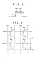
- Fig. 2 shows a representation of an electric circuit of the memory cell.
- Reference symbol S denotes a source region commonly connected to the erase gate; D, a drain region; FG, a floating gate; CG1, a first control gate; and CG2, a second control gate.
- the memory array having a plurality of memory cells as described above, is formed on the p-Si substrate in a matrix form.
- the n +- layer 10 for connecting the source region 3 and the erase gate 8 are continuously formed along a plurality of memory cells on each row and serve as the source control line.
- the first control gate 6 is continuously formed along a plurality of memory cells on each column and serves as the column control line.
- the second control gate 7 is also continuously formed along the plurality of memory cells on each row and serves as the row control line.
- the drain region 4 is commonly connected to the plurality of memory cells on each column through a metal wiring layer (not shown), which serves as the drain control line.
- Fig. 3 shows an equivalent circuit of the 4-bit memory array.
- Reference symbols Ml to M4 denote memory cells, D1 and D2, drain control lines, Sl and 52, source control lines, CG21 and CG22, row control lines, and CG11 and CG12, column control lines.
- the source control lines 51 and S2 are commonly connected to a source driver (not shown).
- the writing operation of the memory cell Ml is described with reference to the conventional method.
- a high voltage (+20 V) is applied to the row control line CG21 and the column control line CG11
- a low voltage (0 V) is applied to the row control line CG22, the column control line CG12, the drain control lines Dl, and D2 and the source control lines Sl and S2.
- the high voltage is applied to one of the two control gates of each of the cells and the cells are set in the half-selected mode.
- a low voltage of 0 V is applied to the nonselected row control line CG22 and the nonselected column control line CG12
- a low voltage of +5 V is applied to the source control lines Sl and S2
- a high voltage of + 25 V is applied to the selected row and column control lines CG21 and CG11.
- the p-Si substrate potential is set at 0 V.
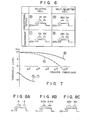
- Fig. 4 shows the relationships between the the selected and half-selected cells of the matrix of this embodiment and between those of the conventional method.
- the writing conditions (potentials) of a selected cell in the conventional case and the selected cell of this embodiment are substantially the same.
- the write conditions (potentials) of a half-selected cell in the conventional case and the half-selected cell of this embodiment differ from each other.
- an electric field applied to the Si0 2 layer on the erase gate in the half-selected cell (4: is smaller than that in the half-selected cell in the conventional case.
- changes in threshold level of the half-selected cell are smaller than those of the half-selected cell in the conventional case.
- the memory cell Ml is erased in a different manner compared to the conventional case wherein the corresponding cell is erased.
- a low voltage (0 V) is applied to the row and column control lines CG21 and CG11
- a high voltage (+20 V) is applied to the row and column control lines CG22 and CG12 and the source control lines S1 and S2.
- the high voltage is applied to one of the two control gates of each of the corresponding cells, and the cells are set in the half-selected state.
- a low voltage of O V is applied to the selected row and column control lines CG21 and CG11
- a high voltage of +20 V is applied to the source control lines S1 and S2
- a high voltage of +25 V is applied to the remaining row and column control lines CG22 and CG12.
- the p-Si substrate potential is set to be 0 V.
- Fig. 6 shows the relationships between the potentials at the selected and half-selected cells of this embodiment and between those in the conventional case.
- the potential at a selected cell in the conventional case is substantially the same as that at a selected cell in this embodiment.
- the potential at a half-selected cell of this embodiment differs from that at a half-selected cell in the conventional case.
- changes in the threshold level of the half-selected cell are smaller than those of the half-selected cell in the conventional case.
- Fig. 8A assume that potentials A and B are applied to the two control gates and that potential x is applied to the erase gate.
- an electric field applied to the insulating film on the erase gate can be equivalently illustrated as in Fig. 8B.
- Reference symbol k in Fig. 8B denotes a constant determined by capacitive coupling between the first and second control gates and the floating gate.
- the conditions are preset so that the constant k is set to be 1. The reason for this will be described later on.
- the reason why the constant k is set to be substantially 1 is given as follows. Assume that the capacitances between the first control gate and the floating gate and between the second control gate and the floating gate are given to be CCF1 and CCF2, a capacitance between the floating gate and the erase gate is given to be CE, and a capacitance between the floating gate and the substrate is given to be CFS. At the same time, assume that the potentials at the first and second control gates are given to be VCG1 and VCG2, a potential at the erase gate is given to be VE, and a substrate potential is given to be VS.
- a potential VFG at the floating gate is given as follows:
- the write and erase characteristics depend on a potential difference (VFG - VE) between the floating gate and the erase gate.
- VFG - VE potential difference
- Fig. 9 shows an 8-bit write type memory array matrix.
- Memory cells M(i,j) are grouped on rows in units of eight bits.
- Eight column control lines CG11, CG12,..., and CG18 of the memory cells of each block are commonly connected to terminals Al, A2,... in units of blocks through the transfer gate MOSFETs Ql, Q2,... and Q8, respectively.
- the gates of the MOSFETs Ql, Q2,..., and Q8 of the respective blocks are commonly connected to terminals Bl, B2,..., and B8.
- Row control lines CG21, CG22,..., and CG2n are provided in units of rows independent of blocks.
- Reference symbol S denotes a common source control line of all bits.
- the drain control line is omitted in Fig. 9.
- Data updating of the memory array matrix will be performed in the following manner. Assume that the memory cells M(l,l) and M(1,9) are to be updated. A low voltage is applied to the row control line CG21 and the column control lines CG11 of the respective blocks, and a high voltage is applied to the remaining row and column control lines and the source control line. Electrons are discharged from the floating gates of the memory cells M(l,l) and M(l,9) irrespective of the previous operating conditions, so that the cells M(l,l) and M(1,9) are set in the erased state ("0").
- the high voltage is applied to the terminal Bl, and the low voltage is applied to the remaining terminals B2,..., and B8.
- the low voltage is applied to the terminal Al, and the high voltage is applied to the terminal A2.
- the high voltage is applied to the row control line CG21, and the low voltage is applied to the remaining row control lines CG22,..., and CG2n and the source control line S.
- the memory cell M(l,l) is set at logic "0".
- electrons are injected in the floating gate of the memory cell M(1,9), so that the memory cell M(l,9) is set at logic "1".
- the source control line 5 is common to all bits. However, independent source control lines may be arranged for respective blocks.
- the memory array may be grouped into a plurality of blocks along the column direction. In this case, a decoder is required to select the source control line, but the number of half-selected memory cells can be decreased.
- decoders for setting the potentials at the row, column, and source control lines in the erasing and writing modes as described above are illustrated in Figs. 10 to 12.
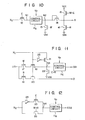
- Fig. 10 shows a source decoder.
- Reference symbol XS denotes an input signal
- 11 denotes a boosted potential (+25 V).
- Vcc is set at 5 V
- Vss is set at 0 V.
- Reference symbols E, W, and R denote control signals which are set at "H" level in the erasing, writing, and reading modes, respectively.
- Reference numerals 12 to 16 denote n-channel E-type MOSFETs.
- the operation of the source decoder is performed in the following manner.
- XS "H” is established, so that the node N1 is set at "H” level.
- the voltage Vp drops through the MOSFET 14 and becomes 20 V, so that a voltage of +20 V is applied to the source control line S.
- Fig. 11 shows a column decoder for selecting column and drain control lines.
- Reference symbol XC denotes an input signal
- I/O denotes a data input/output signal.
- the Vp control circuit 11C has the same arrangement as the Vp control circuit 11S of Fig. 10.
- Reference numerals 17 to 22 denote n-channel E-type MOSFETs; and 23 denotes an inverter.
- the MOSFET 22 In the erasing mode, the MOSFET 22 is turned on. In this case, a node N3 is set at 0 V irrespective of the logic level of XC, so that a voltage of 0 V is applied to a column control line CG1. Since the MOSFET 19 is held OFF, a drain control line D is set at a floating potential.
- the MOSFET 19 is also held OFF in the writing mode, so that the drain control line D is kept at the floating potential. In the reading mode, the MOSFETs 19 and 22 are turned on.
- the MOSFET 20 in the selected circuit is turned on. A voltage of 0 V is applied to the column control line CG1, and the selected drain control line D is connected to the output circuit.
- Fig. 12 shows a row decoder for selecting a row control line.
- Reference symbol XR denotes an input signal.
- a Vp control circuit 11R has the same arrangement as the Vp control circuits 11S and 11C of Figs. 10 and 11.
- Reference numeral 24 denotes an inverter, and 25 and 26 denote n-channel E-type MOSFETs.
- the MOSFET 25 is turned on and the MOSFET 26 is turned off.
- the output is then inverted by the inverter 24, and an inverted signal (0 V) appears at a node N4. Therefore, a voltage of 0 V is applied from the selected circuit to the row control line CG2.
- the MOSFET 25 is turned off, and the MOSFET 26 is turned on.
- the output is set at 0 V.
- the operation in the reading mode is the same as that in the writing mode.
- writing and erasing are controlled in accordance with combinations of potentials of 0 V, +5 V, +20 V, and +25 V.
- the present invention is not limited to this mode of operation.
- the relationship of potentials described above can be arbitrarily selected in accordance with the memory cell structure, the capacitances between the first control gate and the floating gate and the second control gate and the floating gate, the capacitance between the erasing gate and the floating gate, and necessary write time.
- a positive voltage power supply is used.
- a negative voltage power supply can be used if the relationship of potentials similar to that described above is established.
- the present invention can also be applied to a case wherein memory cell array and their peripheral circuits comprise p-channel type elements.
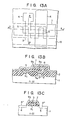
- a p-channel type memory cell structure is shown in Figs. 13A to 13C, corresponding to the views shown in Figs. 1A to 1C.
- writing is performed such that holes are injected from the p-type erasing gate to the floating gate.
- Erasing is performed such that holes charged by the floating gate are discharged to the erasing gate.
- the relationship of potentials among the components corresponds to the one given in the above embodiment, but is inverted.
- the positive potentials at the respective components of the above embodiment are inverted to negative potentials to obtain the same effect as in the above embodiment.
- a negative power supply is used, a voltage of 0 V or a low negative voltage is applied as the low voltage, and a high negative voltage is used as the high voltage selectively applied to the components.
Landscapes
- Non-Volatile Memory (AREA)
- Read Only Memory (AREA)
- Semiconductor Memories (AREA)
Applications Claiming Priority (2)
| Application Number | Priority Date | Filing Date | Title |
|---|---|---|---|
| JP58180512A JPS6074577A (ja) | 1983-09-30 | 1983-09-30 | 不揮発性半導体メモリ装置 |
| JP180512/83 | 1983-09-30 |
Publications (3)
| Publication Number | Publication Date |
|---|---|
| EP0136771A2 true EP0136771A2 (de) | 1985-04-10 |
| EP0136771A3 EP0136771A3 (en) | 1986-12-30 |
| EP0136771B1 EP0136771B1 (de) | 1988-04-13 |
Family
ID=16084543
Family Applications (1)
| Application Number | Title | Priority Date | Filing Date |
|---|---|---|---|
| EP84303503A Expired EP0136771B1 (de) | 1983-09-30 | 1984-05-23 | Nichtflüchtige Halbleiterspeicheranordnung |
Country Status (4)
| Country | Link |
|---|---|
| US (1) | US4630087A (de) |
| EP (1) | EP0136771B1 (de) |
| JP (1) | JPS6074577A (de) |
| DE (1) | DE3470439D1 (de) |
Cited By (4)
| Publication number | Priority date | Publication date | Assignee | Title |
|---|---|---|---|---|
| EP0204499A3 (de) * | 1985-05-29 | 1988-12-14 | Advanced Micro Devices, Inc. | Hochspannungsisolierungsschaltung für CMOS-Netzwerke |
| EP0317324A3 (de) * | 1987-11-17 | 1991-01-16 | Kabushiki Kaisha Toshiba | Programmierbarer Halbleiterspeicher |
| US5327378A (en) * | 1992-03-04 | 1994-07-05 | Waferscale Integration, Inc. | Easily manufacturable compact EPROM |
| US6288941B1 (en) | 1989-08-18 | 2001-09-11 | Hitachi, Ltd. | Electrically erasable semiconductor non-volatile memory device having memory cell array divided into memory blocks |
Families Citing this family (13)
| Publication number | Priority date | Publication date | Assignee | Title |
|---|---|---|---|---|
| USRE37308E1 (en) * | 1986-12-22 | 2001-08-07 | Stmicroelectronics S.R.L. | EEPROM memory cell with a single level of polysilicon programmable and erasable bit by bit |
| IT1199828B (it) * | 1986-12-22 | 1989-01-05 | Sgs Microelettronica Spa | Cella di memoria eeprom a singolo livello di polisilicio scrivibile e cancellabile bit a bit |
| JPS6432494A (en) * | 1987-07-27 | 1989-02-02 | Mitsubishi Electric Corp | Non-volatile semiconductor storage device |
| JP2685825B2 (ja) * | 1988-08-12 | 1997-12-03 | 株式会社東芝 | 不揮発性半導体メモリ |
| JP2679389B2 (ja) * | 1990-10-12 | 1997-11-19 | 日本電気株式会社 | 不揮発性半導体記憶セルのデータ消去方法 |
| KR940005695B1 (ko) * | 1990-12-19 | 1994-06-22 | 삼성전자 주식회사 | 불휘발성 기억소자의 로우 디코더 회로 |
| KR960702157A (ko) * | 1994-02-15 | 1996-03-28 | 타다시 시바타 | 반도체 장치 |
| JP2590744B2 (ja) * | 1994-07-28 | 1997-03-12 | 日本電気株式会社 | 不揮発性半導体記憶装置 |
| US5761121A (en) * | 1996-10-31 | 1998-06-02 | Programmable Microelectronics Corporation | PMOS single-poly non-volatile memory structure |
| US5818082A (en) * | 1996-03-04 | 1998-10-06 | Advanced Micro Devices, Inc. | E2 PROM device having erase gate in oxide isolation region in shallow trench and method of manufacture thereof |
| US5889303A (en) * | 1997-04-07 | 1999-03-30 | Motorola, Inc. | Split-Control gate electrically erasable programmable read only memory (EEPROM) cell |
| JP3159152B2 (ja) * | 1997-12-26 | 2001-04-23 | 日本電気株式会社 | 不揮発性半導体記憶装置及び不揮発性半導体記憶装置のデータ消去方法 |
| JP2004297028A (ja) * | 2003-02-04 | 2004-10-21 | Sharp Corp | 半導体記憶装置 |
Family Cites Families (5)
| Publication number | Priority date | Publication date | Assignee | Title |
|---|---|---|---|---|
| US3825946A (en) * | 1971-01-15 | 1974-07-23 | Intel Corp | Electrically alterable floating gate device and method for altering same |
| US3728695A (en) * | 1971-10-06 | 1973-04-17 | Intel Corp | Random-access floating gate mos memory array |
| JPS6014438B2 (ja) * | 1979-08-29 | 1985-04-13 | 株式会社東芝 | 不揮発性半導体メモリ− |
| JPS57141969A (en) * | 1981-02-27 | 1982-09-02 | Toshiba Corp | Nonvolatile semiconductor memory |
| JPS57157573A (en) * | 1981-03-25 | 1982-09-29 | Fujitsu Ltd | Semiconductor non-volatile memory cell |
-
1983
- 1983-09-30 JP JP58180512A patent/JPS6074577A/ja active Pending
-
1984
- 1984-05-22 US US06/613,059 patent/US4630087A/en not_active Expired - Lifetime
- 1984-05-23 DE DE8484303503T patent/DE3470439D1/de not_active Expired
- 1984-05-23 EP EP84303503A patent/EP0136771B1/de not_active Expired
Cited By (5)
| Publication number | Priority date | Publication date | Assignee | Title |
|---|---|---|---|---|
| EP0204499A3 (de) * | 1985-05-29 | 1988-12-14 | Advanced Micro Devices, Inc. | Hochspannungsisolierungsschaltung für CMOS-Netzwerke |
| EP0317324A3 (de) * | 1987-11-17 | 1991-01-16 | Kabushiki Kaisha Toshiba | Programmierbarer Halbleiterspeicher |
| EP0317323A3 (de) * | 1987-11-17 | 1991-01-16 | Kabushiki Kaisha Toshiba | Programmierbarer Halbleiterspeicher |
| US6288941B1 (en) | 1989-08-18 | 2001-09-11 | Hitachi, Ltd. | Electrically erasable semiconductor non-volatile memory device having memory cell array divided into memory blocks |
| US5327378A (en) * | 1992-03-04 | 1994-07-05 | Waferscale Integration, Inc. | Easily manufacturable compact EPROM |
Also Published As
| Publication number | Publication date |
|---|---|
| US4630087A (en) | 1986-12-16 |
| EP0136771A3 (en) | 1986-12-30 |
| EP0136771B1 (de) | 1988-04-13 |
| JPS6074577A (ja) | 1985-04-26 |
| DE3470439D1 (en) | 1988-05-19 |
Similar Documents
| Publication | Publication Date | Title |
|---|---|---|
| EP0639860B1 (de) | Nichtflüchtiger Halbleiterspeicher | |
| US5465231A (en) | EEPROM and logic LSI chip including such EEPROM | |
| US5936887A (en) | Non-volatile memory device with NAND type cell structure | |
| US7974148B2 (en) | Semiconductor memory device using only single-channel transistor to apply voltage to selected word line | |
| EP0247875B1 (de) | Blockmässig elektrisch löschbarer Speicher | |
| US5673224A (en) | Segmented non-volatile memory array with multiple sources with improved word line control circuitry | |
| US5740107A (en) | Nonvolatile integrated circuit memories having separate read/write paths | |
| USRE37311E1 (en) | Parallel type nonvolatile semiconductor memory device and method of using the same | |
| KR100234609B1 (ko) | 반도체 기억 장치 | |
| US6380636B1 (en) | Nonvolatile semiconductor memory device having an array structure suitable to high-density integrationization | |
| EP0447856B1 (de) | Nichtflüchtiger Halbleiterspeicher | |
| US4630087A (en) | Nonvolatile semiconductor memory device | |
| US5812454A (en) | Nand-type flash memory device and driving method thereof | |
| EP0320916B1 (de) | Elektrisch löschbarer und programmierbarer Festwertspeicher mit Stapelgatterzellen | |
| US4527259A (en) | Semiconductor device having insulated gate type non-volatile semiconductor memory elements | |
| US6104057A (en) | Electrically alterable non-volatile semiconductor memory device | |
| US5177705A (en) | Programming of an electrically-erasable, electrically-programmable, read-only memory array | |
| US20020158282A1 (en) | Non-volatile memory with a serial transistor structure with isolated well and method of operation | |
| US6563728B2 (en) | Semiconductor memory device and method for operation thereof | |
| KR100639827B1 (ko) | Eeprom 응용을 위한 1 트랜지스터 셀 | |
| JPH02223097A (ja) | 不揮発性半導体メモリ装置 | |
| US6291843B1 (en) | Semiconductor memory device | |
| US5394357A (en) | Non-volatile semiconductor memory device | |
| US6272045B1 (en) | Nonvolatile semiconductor memory device | |
| JPH035674B2 (de) |
Legal Events
| Date | Code | Title | Description |
|---|---|---|---|
| PUAI | Public reference made under article 153(3) epc to a published international application that has entered the european phase |
Free format text: ORIGINAL CODE: 0009012 |
|
| 17P | Request for examination filed |
Effective date: 19840606 |
|
| AK | Designated contracting states |
Designated state(s): DE FR GB |
|
| PUAL | Search report despatched |
Free format text: ORIGINAL CODE: 0009013 |
|
| AK | Designated contracting states |
Kind code of ref document: A3 Designated state(s): DE FR GB |
|
| 17Q | First examination report despatched |
Effective date: 19870630 |
|
| GRAA | (expected) grant |
Free format text: ORIGINAL CODE: 0009210 |
|
| AK | Designated contracting states |
Kind code of ref document: B1 Designated state(s): DE |
|
| REF | Corresponds to: |
Ref document number: 3470439 Country of ref document: DE Date of ref document: 19880519 |
|
| PLBE | No opposition filed within time limit |
Free format text: ORIGINAL CODE: 0009261 |
|
| STAA | Information on the status of an ep patent application or granted ep patent |
Free format text: STATUS: NO OPPOSITION FILED WITHIN TIME LIMIT |
|
| 26N | No opposition filed | ||
| PGFP | Annual fee paid to national office [announced via postgrant information from national office to epo] |
Ref country code: DE Payment date: 19970530 Year of fee payment: 14 |
|
| PG25 | Lapsed in a contracting state [announced via postgrant information from national office to epo] |
Ref country code: DE Free format text: LAPSE BECAUSE OF NON-PAYMENT OF DUE FEES Effective date: 19990302 |