EP0136865A2 - Elektromagnetisches Lager - Google Patents
Elektromagnetisches Lager Download PDFInfo
- Publication number
- EP0136865A2 EP0136865A2 EP84306378A EP84306378A EP0136865A2 EP 0136865 A2 EP0136865 A2 EP 0136865A2 EP 84306378 A EP84306378 A EP 84306378A EP 84306378 A EP84306378 A EP 84306378A EP 0136865 A2 EP0136865 A2 EP 0136865A2
- Authority
- EP
- European Patent Office
- Prior art keywords
- magnetic
- yoke
- supported body
- magnetic poles
- electromagnetic bearing
- Prior art date
- Legal status (The legal status is an assumption and is not a legal conclusion. Google has not performed a legal analysis and makes no representation as to the accuracy of the status listed.)
- Granted
Links
Images



Classifications
-
- F—MECHANICAL ENGINEERING; LIGHTING; HEATING; WEAPONS; BLASTING
- F16—ENGINEERING ELEMENTS AND UNITS; GENERAL MEASURES FOR PRODUCING AND MAINTAINING EFFECTIVE FUNCTIONING OF MACHINES OR INSTALLATIONS; THERMAL INSULATION IN GENERAL
- F16C—SHAFTS; FLEXIBLE SHAFTS; ELEMENTS OR CRANKSHAFT MECHANISMS; ROTARY BODIES OTHER THAN GEARING ELEMENTS; BEARINGS
- F16C32/00—Bearings not otherwise provided for
- F16C32/04—Bearings not otherwise provided for using magnetic or electric supporting means
- F16C32/0406—Magnetic bearings
- F16C32/044—Active magnetic bearings
- F16C32/0459—Details of the magnetic circuit
- F16C32/0461—Details of the magnetic circuit of stationary parts of the magnetic circuit
- F16C32/0465—Details of the magnetic circuit of stationary parts of the magnetic circuit with permanent magnets provided in the magnetic circuit of the electromagnets
-
- F—MECHANICAL ENGINEERING; LIGHTING; HEATING; WEAPONS; BLASTING
- F16—ENGINEERING ELEMENTS AND UNITS; GENERAL MEASURES FOR PRODUCING AND MAINTAINING EFFECTIVE FUNCTIONING OF MACHINES OR INSTALLATIONS; THERMAL INSULATION IN GENERAL
- F16C—SHAFTS; FLEXIBLE SHAFTS; ELEMENTS OR CRANKSHAFT MECHANISMS; ROTARY BODIES OTHER THAN GEARING ELEMENTS; BEARINGS
- F16C32/00—Bearings not otherwise provided for
- F16C32/04—Bearings not otherwise provided for using magnetic or electric supporting means
- F16C32/0406—Magnetic bearings
- F16C32/044—Active magnetic bearings
- F16C32/0474—Active magnetic bearings for rotary movement
-
- H—ELECTRICITY
- H01—ELECTRIC ELEMENTS
- H01J—ELECTRIC DISCHARGE TUBES OR DISCHARGE LAMPS
- H01J35/00—X-ray tubes
- H01J35/02—Details
- H01J35/04—Electrodes ; Mutual position thereof; Constructional adaptations therefor
- H01J35/08—Anodes; Anti cathodes
- H01J35/10—Rotary anodes; Arrangements for rotating anodes; Cooling rotary anodes
- H01J35/101—Arrangements for rotating anodes, e.g. supporting means, means for greasing, means for sealing the axle or means for shielding or protecting the driving
- H01J35/1017—Bearings for rotating anodes
- H01J35/103—Magnetic bearings
-
- F—MECHANICAL ENGINEERING; LIGHTING; HEATING; WEAPONS; BLASTING
- F16—ENGINEERING ELEMENTS AND UNITS; GENERAL MEASURES FOR PRODUCING AND MAINTAINING EFFECTIVE FUNCTIONING OF MACHINES OR INSTALLATIONS; THERMAL INSULATION IN GENERAL
- F16C—SHAFTS; FLEXIBLE SHAFTS; ELEMENTS OR CRANKSHAFT MECHANISMS; ROTARY BODIES OTHER THAN GEARING ELEMENTS; BEARINGS
- F16C2300/00—Application independent of particular apparatuses
- F16C2300/20—Application independent of particular apparatuses related to type of movement
-
- F—MECHANICAL ENGINEERING; LIGHTING; HEATING; WEAPONS; BLASTING
- F16—ENGINEERING ELEMENTS AND UNITS; GENERAL MEASURES FOR PRODUCING AND MAINTAINING EFFECTIVE FUNCTIONING OF MACHINES OR INSTALLATIONS; THERMAL INSULATION IN GENERAL
- F16C—SHAFTS; FLEXIBLE SHAFTS; ELEMENTS OR CRANKSHAFT MECHANISMS; ROTARY BODIES OTHER THAN GEARING ELEMENTS; BEARINGS
- F16C2380/00—Electrical apparatus
- F16C2380/16—X-ray tubes
Definitions
- the present invention relates to an electromagnetic bearing for magnetically supporting a supported body in suspension, and more specifically to an electromagnetic bearing having a simple, compact structure which more efficiently uses its magnetic flux.
- Electromagnetic bearings are conventionally known as bearings for supporting a supported body such as a rotating body, in which the supported body is levitated by magnetic force so that it is not in contact with any stationary part.
- these magnetic bearings provide various advantages, such as no mechanical friction, no mechanical noise, high-speed rotation, etc.
- a cylindrical rotating body or supported body 12 is disposed in a case 10.
- a cylindrical member 14 of the supported body 12 is formed of a nonmagnetic material.
- a pair of ring-shaped members 16 is attached to the upper and lower portions of the inner peripheral surface of the cylindrical member 14.
- the ring-shaped members 16 are-Tormed of a ferromagnetic material.
- a magnetic supporting means 20 is set on a base 22 at the bottom of the case 10.
- Two groups of magnetic poles 26 and 30 are formed on the upper and lower end portions, respectively, of a yoke 24 of the magnetic supporting means 20.
- Each group 26 or 30 includes four magnetic poles 26a, 26b, 26c and 26d (shown in Fig. 2) or 30a, 30b, 30c and 30d (only 30a and 30c are shown in Fig. 1) which protrude at a right angle to the longitudinal direction of the yoke 24 from the central portion thereof toward the ring-shaped members 16 and intersect it at right angles.
- the groups of magnetic poles 26 and 30 face the upper portion of the upper ring-shaped member 16 and the lower portion of the lower ring-shaped member 16, respectively.
- a ring-shaped magnetic pole 34 is formed on that portion of the yoke 24 which extends between the two groups of magnetic poles 26 and 30.
- the ring-shaped magnetic pole 34 faces that portion of the cylindrical member 14 which extends between the two ring-shaped members 16.
- Ring-shaped permanent magnets 39 and 40 are arranged on those portions of the yoke 24 between the one group of magnetic poles 26 and the magnetic pole 34 and between the other group of magnetic poles 30 and the magnetic pole 34.
- Coils 28a, 28b, 28c, 28d, 32a, 32b, 32c and 32d (32b and 32d are not shown in Fig. 1) for adjusting the radial position of the supported body l2 are wound around the magnetic poles 26a, 26b, 26c, 26d, 30a, 30b, 30c and 30d, respectively.
- a pair of coils 36 and 38 wound around the yoke 24 is arranged individually on two flat surfaces of the ring-shaped magnetic pole 34.
- the coils 36 and 38 are used for adjusting the longitudinal position of the supported body 12. These coils are energized for controlling the following fluxes, and a magnetic flux delivered from the north pole of the permanent magnet 39 passes through the yoke 24 in loops indicated by the broken lines in Fig. 1, enters the ring-shaped members 16 via the groups of magnetic poles 26 and 34, and returns to the south pole of the permanent magnet 39.
- magnetic flux delivered from the permanent magnet 40 which flux should be controlled by the energized coil returns thereto circulating in loops as indicated by the broken lines in Fig. 1.
- magnetic flux from the magnetic pole 26a enters the upper ring-shaped member 16 substantially at right angles to the peripheral surface thereof. Therefore, if the energizing current of the coil 28a is increased to raise the magnetic flux density, the supported body 12 moves toward the magnetic pole 26a. Thus, the radial position of the supported body 12 can be adjusted by regulating the energizing currents of the groups of coils 28 and 32. Meanwhile, magnetic flux from the magnetic pole 34 enters the ring-shaped members 16 substantially at right angles to the lower and upper end faces of the upper and lower ring-shaped members 16.
- the energizing currents of the coils 36 and 38 are increased and decreased, respectively, so that the magnetic fluxes from the magnetic pole 34 which enter the upper and lower ring-shaped members 16 are intensified and weakened, respectively.
- the force of attraction between the upper ring-shaped member 16 and the magnetic pole 34 is increased to lower the supported body 12.
- the longitudinal and radial positions of the supported body 12 can individually be adjusted by regulating the coil energizing currents.
- At least three electromagnets are arranged equidistantly on the circumference of a circle at each end of a rotating shaft.
- the electromagnets are positioned at an angle to the axis of the rotating shaft.
- a supported body is levitated by being subjected to a magnetic force in the axial and radial directions of the rotating shaft given by the slanted electromagnets.
- the required magnetic poles for the magnetic bearing may be reduced in number.
- the supported body can be moved in one direction only after the energizing currents of a number of coils are calculated correlatively. This calculation is quite complicated; it is difficult to set the optimum current values and the control constant for position adjustment.
- the direction of the magnetic force acting on the supported body and the direction in which the supported body is to be moved are not coincident, intersecting each other at an angle of 90° or less.
- the components of the magnetic force at right angles to the direction of the movement of the supported body match with and cancel each other.
- the presence of the magnetic force in the aforesaid perpendicular direction leads to a waste of current for driving the electromagnets.
- the magnetic force component applied in the direction of the movement of the supported body is smaller than the increment of the magnetic force caused by the increase of the current, so that the current efficiency is low. Since the supported body and the electromagnets are inclined, it is hard to increase structural accuracy, and the setting accuracy is low.
- the object of the present invention is to provide an electromagnetic bearing simple in construction, small in sized, which efficiently uses magnetic flux, and which is capable of stably supporting an object to be supported.
- An electromagnetic bearing comprises magnetic supporting means and a supported body.
- the magnetic supporting means includes an elongated yoke; first and second groups of magnetic poles on the yoke spaced apart along the longitudinal direction of the yoke, each of the two groups including a plurality of magnetic poles protruding from the yoke and perpendicular to the longitudinal direction of the yoke; first and second groups of coils including a plurality of first and second coils wound around the first and second groups of magnetic poles, each of the first and second coils being adapted to produce magnetic flux along the protruding direction of each corresponding pole; and a third coil for producing magnetic flux along the longitudinal direction of the yoke.
- the supported body includes a magnetic coupling member formed of a highly permeable material, the magnetic coupling member extending along the longitudinal direction of the yoke and having end portions aligned individually with the first and second groups of magnetic poles, whereby magnetic fluxes, in order to enter and leave the magnetic coupling member in the direction substantially perpendicular to the longitudinal direction of the magnetic coupling member, are formed between the magnetic poles and the magnetic coupling member by the first and the second coils, and whereby magnetic fluxes, which enter and leave the magnetic coupling member substantially at right angles to their end faces, are formed between the magnetic poles and the magnetic coupling member by the third coil.
- the supported body is supported and suspended by the magnetic supporting means.
- a perpendicular magnetic force is applied to the end faces of the magnetic coupling member by the magnetic flux produced by the third coil. Also, perpendicular magnetic forces are applied to the peripheral surface of the magnetic coupling member by the magnetic fluxes produced by the first and second coils, if the magnetic coupling member is in the form of a hollow cylinder.
- the supported body is supported in suspension (no-contact state).
- the individual magnetic poles of the first and second magnetic pole groups both apply magnetic forces to the magnetic coupling member in the longitudinal direction and in the direction perpendicular to the longitudinal direction. Accordingly, the magnetic poles of the magnetic supporting means are reduced in number, so that the electromagnetic bearing of the invention, is simple in construction and small-sized.
- the direction in which the magnetic fluxes from the magnetic supporting means enter and leave the magnetic coupling member of the supported body is substantially coincident with the moving direction (position control direction) of the supported body.
- the direction of the magnetic forces is coincident with the moving direction of the supported body.
- Fig. 3 is a longitudinal sectional view of an electromagnetic bearing according to one embodiment of the present invention
- Figs. 4 and 5 are sectional views taken along lines IV-IV and V-V of Fig. 3, respectively.
- a cylindrical case 50 having both a top and a bottom is formed of a material which can intercept magnetism.
- the case 50 can prevent the penetration of external magnetism or the leakage of internal magnetism.
- a supported body (object to be supported) 54 formed of a nonmagnetic material is coaxially disposed in the case 50.
- the supported body 54 is composed of a cylindrical member 56 and a top wall 58 at the top of the cylindrical member 56.
- a rotating shaft 64 is fixed to the top wall 58 so as to be coaxial with the cylindrical member 56.
- the rotating shaft 64 passes through a hole 53 in the wall of the case 50 which faces the top wall 58, and is led out of the case 50.
- the rotating shaft 64 is coupled to a suitable object to rotate (not shown).
- a circumferentially extending endless recess 66 is formed in the inner peripheral surface of the cylindrical member 56.
- a magnetic coupling member or ring-shaped member 68 formed of a cylindrical ferromagnetic material is fitted in the recess 66.
- the cylindrical member 56 is formed at the upper and lower ends thereof, respectively, with projecting peripheral wall portions 60 and 62 which extend along the circumferential direction of the cylindrical member 56 and which slightly project along the longitudinal direction of the member 56.
- Bearing means 90 and 91 are fixed to the case 50 so as to face the projecting peripheral wall portions 60 and 62, respectively.
- a magnetic supporting means 70 is disposed inside the supported body 54.
- a yoke 72 of the magnetic supporting means 70 which is formed of a highly permeable material, is fixed on a base 52 of the case 50.
- a group of magnetic poles 74a, 74b, 74c and 74d and another group of magnetic poles 78a, 78b, 78c and 78d are formed on the upper and lower ends, respectively, of the yoke 72, protruding therefrom toward the inner peripheral surface of the supported body 54.
- the magnetic poles 74a, 74b, 74c and 74d are arranged so that a straight line connecting the centers of the magnetic poles 74a and 74c and a straight line connecting the centers of the magnetic poles 74b and 74d intersect at right angles on the center of the yoke 72.
- the magnetic poles of the magnetic pole group 78 are arranged in the same manner as those of the magnetic pole group 74.
- the centers of the magnetic poles of the two magnetic pole groups 74 and 78 are aligned with their corresponding ends of the ring-shaped member 68.
- the distance between each magnetic pole and the inner peripheral surface of the supported body 54 is suitably set.
- Coils 76a, 76b, 76c, 76d, 80a, 80b, 80c and 80d for adjusting the radial position of the supported body 54 are wound around the magnetic poles 74a, 74b, 74c, 74d, 78a, 78b, 78c and 78d, respectively. Meanwhile, a coil 82 for adjusting the longitudinal position of the supported body 54 is wound around that portion of the yoke 72 which extends between the two magnetic pole groups 74 and 78.
- Two groups of sensors 100 and 102 for detecting the radial position of the supported body 54 are attached to the case 50, facing their corresponding magnetic pole groups 74 and 78 with the supported body 54 between them.
- Sensors 100a, 100b, 100c and 100d of the sensor group 100 and sensors 102a, 102b, 102c and 102d of the sensor group 102 face the magnetic poles 74a, 74b, 74c, 74d, 78a, 78b, 78c and 78d, respectively, with the supported body 54 between them.
- sensors 104a and 104b of a sensor group 104 for detecting the longitudinal position of the supported body 54 are disposed in positions facing the lower projecting peripheral wall portion 62 of the cylindrical member 56. These sensors may be formed of eddy-current displacement gauges or the like. The position of the supported body 54 is detected by using the two sensors 104a and 104b in a differential manner.
- a motor 92 for rotating the supported body 54 is disposed in the vicinity of the upper projecting peripheral wall portion 60 of the cylindrical member 56.
- the motor 92 includes a stator 94 fixed to the inner peripheral surface of the case 50 and a rotor 98 fixed to the outer peripheral surface of the cylindrical member 56.
- a coil 96 is wound around the stator 94. The supported body 54 supported in suspension by the magnetic supporting means 70 is rotated by the motor 92.
- the output of the sensors 100, 102 and 104 is applied to the input of the control devices (not shown) to adjust the radial and longitudinal directions of the supported body 54.
- These control devices adjust the position of the supported body 54 by changing the currents flowing through the coils if the position of the supported body 54 detected by the sensors is deviated from a predetermined position.
- magnetic fluxes produced by the coil 82 pass through the yoke 72, and enter the upper end of the ring-shaped member 68 of the supported body 54 substantially at right angles to the upper end face thereof via the magnetic poles 74a, 74b, 74c and 74d. Then, the magnetic fluxes pass through the ring-shaped member 68, escape from the lower end of the ring-shaped member 68 substantially at right angles to the lower end face thereof, and enter the magnetic poles 78a, 78b, 78c and 78d.
- the magnetic fluxes from the coil 82 produce a magnetic force which acts on the ring-shaped member 68 at right angles to the end faces thereof (in the longitudinal direction), so that the supported body 54 is supported and suspended.
- part of the magnetic flux directed from the magnetic pole 74a toward the ring-shaped member 68 enters the ring-shaped member 68 at right angles to the inner peripheral surface thereof.
- This magnetic flux produces a magnetic force to act radially on the ' supported body 54.
- This magnetic force and the magnetic force acting between the opposite magnetic pole 74c and the ring-shaped member 68 cancel each other.
- the supported body 54 will never be subjected to the radial force attributed to the magnetic fluxes produced by the coil 82.
- magnetic fluxes produced by the coil 76a enter the ring-shaped member 68 via the magnetic pole 74a substantially at right angles to the inner peripheral surface of the ring-shaped member 68, pass through the ring-shaped member 68 along its circumferential direction, and return to the magnetic pole 74a via the magnetic poles 74b and 74d.
- magnetic fluxes produced by the coil 76c enter the ring-shaped member 68 via the magnetic pole 74 substantially at right angles to the inner peripheral surface of the ring-shaped member 68, pass through the ring-shaped member 68 along its circumferential direction, and return to the magnetic pole 74c via the magnetic poles 74b and 74d.
- magnetic forces act in the direction substantially perpendicular to the inner peripheral surface of the ring-shaped member 68 between the ring-shaped member 68 and the magnetic poles 74a, 74b, 74c and 74d, and the supported body 54 is supported in its radial direction.
- magnetic fluxes produced by the coil group 80 flow in loops as indicated by the broken lines 6 in Fig. 6.
- the magnetic fluxes caused by the coil 80a enter the ring-shaped member 68 via the magnetic poles 78a and 78b or 78d substantially at right angles to the inner peripheral surface of the ring-shaped member 68, pass through the ring-shaped member 68 along the circumferential direction thereof, and return to the magnetic pole 78a.
- the magnetic fluxes caused by the coil 80c enter the ring-shaped member 68 via the magnetic poles 78c and 78b or 78d substantially at right angles to the inner peripheral surface of the ring-shaped member 68, pass through the ring-shaped member 68 along the circumferential direction thereof, and return to the magnetic pole 78c.
- magnetic forces act in the radial direction of the ring-shaped member 68 between the ring-shaped member 68 and the magnetic pole group 78, and the supported body 54 is supported in its radial direction. Consequently, the supported body 54 is supported at its upper and lower end portions by radial magnetic forces from the magnetic pole groups 74 and 78, respectively.
- the supported body 54 rotates, so that the object of rotation is rotated through the medium of the rotating shaft 64.
- the supported body 54 radially shifts its position. For example, if the supported body 54 moves toward the magnetic pole 74a, the distance between the sensor 100a and the supported body 54 is widened, while that between the sensor 100c and the supported body 54 is narrowed.
- the outputs of the sensors 100a and 100c are applied to the input of the control device for radial position adjustment, whereby the coil energizing currents are corrected in accordance with the displacement of the supported body 54. Namely, the currents flowing through the coils 76a and 76c are decreased and increased, respectively.
- the magnetic flux density between the magnetic pole 74a and the ring-shaped member 68 is lowered, while that between the magnetic pole 74c and the ring-shaped member 68 is raised.
- the force of the magnetic pole 74c to attract the ring-shaped member 68 is intensified, so that the supported body 54 moves toward the magnetic pole 74c.
- the displacement caused by external force is corrected, and the supported body 54 returns to its original position.
- the magnetic fluxes from the magnetic poles 74c and 74a increase and decrease, respectively.
- these magnetic fluxes may be kept constant by adjusting the coil energizing currents so that the increment and decrement of the magnetic fluxes are equal.
- the magnetic flux densities of the magnetic poles 74b and 74d will be changed.
- the changes in the magnetic flux density the magnetic poles 74b and 74d are equivalent, the variations of the magnetic forces acting between the ring-shaped member 68 and the magnetic poles 74b and 74d are equal. Accordingly, the Supported body 54 will never be moved in the direction connecting the magnetic poles 74b and 74d.
- the supported body 54 longitudinally shifts its position. This displacement is detected by the sensors 104a and 104b, and applied to the input of the control device for longitudinal position adjustment.
- the control device modifies the current to flow through the coil 82 in accordance with the displacement. If the supported body 54 is shifted downward, the current flowing through the coil 82 is increased, so that the density of the magnetic fluxes between the ring-shaped member 68 and the magnetic pole groups 74 and 78, as indicated by the broken lines 2 in Fig. 3, is increased.
- the magnetic coupling strength between the yoke 72 and the ring-shaped member 68 is increased, and the top end face of the ring-shaped member 68 is attracted to the magnetic pole group 74, so that the supported body 54 is raised.
- the longitudinal displacement of the supported body 54 caused by the external force is corrected, and the supported body 54 returns to its original position.
- the magnetic forces act to remove the radial and longitudinal displacements of the supported body 54 to restore it to the original position, so that the supported body 54 is supported stably.
- the projecting peripheral wall portions 60 and 62 of the cylindrical member 56 engage the bearing means 90 and 91 so that the supported body 54 is supported mechanically.
- the two groups of magnetic poles 74 and 78 serve also as magnetic poles for supporting the supported body in the radial and longitudinal directions. Therefore, the electromagnetic bearing is simple in construction and small-sized, requiring a reduced number of magnetic poles. Moreover, since the direction in which the supported body is to be moved is coincident with the direction of the magnetic force, the efficiency of the magnetic force is high, ensuring low power consumption.
- Magnetic supporting means 120 is disposed in a case 110.
- a yoke 122 of the magnetic supporting means 120 which is a cylindrical structure formed of a ferromagnetic material, is fitted in a recess 112 cut in the inner wall surface of the case 110.
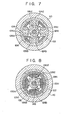
- the magnetic supporting means 120 is provided with two groups of magnetic poles 124 and 128 formed on the upper and lower ends, respectively, of the yoke 122. As shown in Fig.
- the magnetic pole group 124 includes four magnetic poles 124a, 124b, 124c and 124d which are arranged at regular intervals on the inner peripheral surface of the yoke 122 along the circumferential direction thereof and protrude toward the axis of the yoke 122. Coils 126a, 126b, 126c and 126d are wound around the individual magnetic poles 124a, 124b, 124c and 124d, respectively, of the magnetic pole group 124. As shown in Fig.
- the magnetic pole group 128 includes magnetic poles 128a, 128b, 128c and 128d which are arranged on the inner peripheral surface of the yoke 122 along the circumferential direction thereof so as to be in alignment with the magnetic poles 124a, 124b, 124c and 124d, respectively, and protrude toward the axis of the yoke 122.
- Coils 130a, 130b, 130c and 130d are wound around the magnetic poles 128a, 128b, 128c and 128d, respectaively.
- a coil 132 is fitted in the inside space of the yoke 122 between the two magnetic pole groups 124 and 128, extending along the inner peripheral surface of the yoke 122.
- a supported body 140 is passed through the yoke 122.
- a hollow cylindrical member 142 formed of a nonmagnetic material is disposed coaxially with the yoke 122.
- a rotating shaft 144 is coaxially fixed to the lower end of the cylindrical member 142, while a columnar projection 146 is fixed to the upper end of the cylindrical member 142.
- a ring-shaped member 148 formed of a ferromagnetic material is fitted on that portion of the cylindrical member 142 which is surrounded by the yoke 122.
- the ring-shaped member 148 has a length such that its upper end is aligned with the centers of the magnetic poles 124a to 124d of the upper magnetic pole group 124 and its lower end is aligned with those of the magnetic poles 128a to 128d of the lower magnetic pole group 128.
- a motor 92 for rotating the supported body 140 is disposed in the vicinity of the upper end of the cylindrical member 142.
- the motor 92 includes a stator 94 fixed to the case 110, a coil 96 wound around the stator 94, and a rotor 98 fixed to the cylindrical member 142.
- Bearing means 90 and 91 are arranged beside the projection 146 and the rotating shaft 144, respectively.
- Two groups of sensors 100 and 102 for detecting the radial displacement of the supported body 140 are arranged near the upper and lower end portions, respectively, of the cylindrical member 142 of the supported body 140.
- Each of the sensor groups 100 and 102 includes four sensors 100a, 100b, 100c and 100d or 102a, 102b, 102c and 102d (only 100a, 100c, 100d, 102a, 102c and 102d are shown in Fig. 6) which are arranged at intervals along the circumferential direction of the yoke 122 in alignment with their corresponding magnetic poles of the magnetic pole group 124 or 128.
- a sensor 104 for detecting the longitudinal position of the supported body 140 is fixed to the case 110 in the vicinity of the projection 146 on the top end of the cylindrical member 142.
- magnetic fluxes produced by the coil 132 pass through the yoke 122 along its longitudinal direction, and enter the ring-shaped member 148 substantially at right angles to the lower end face thereof, as indicated by broken lines 2 in Fig. 6. Then, the magnetic fluxes pass through the ring-shaped member 148 along its longitudinal direction, and escape from the upper end of the ring-shaped member 148 substantially at right angles to the upper end face thereof.
- the supported body 140 is longitudinally supported by the magnetic fluxes which flow in the loops shown in Fig. 6. Meanwhile, magnetic fluxes delivered from the magnetic pole groups 124 and 128 flow in loops between the individual magnetic poles and the ring-shaped member 148, as indicated by broken lines 4 and 6 in Figs.
- the supported body 140 is supported radially.
- the supported body 140 is supported and suspended by the magnetic supporting means 120. If the supported body 140 is shifted in the longitudinal or radial direction, it is urged to return to its original position by adjusting the currents to flow through the coils. Thus, the supported body 140 is supported stably.
- this embodiment produces the same effect as the first embodiment shown in Figs. 3 to 5.
- This third embodiment differs from the first embodiment of Figs. 3 to 5 in that the coil 82 for adjusting the longitudinal position of the supported body 52 is divided into two coil portions 82a and 82b arranged along the longitudinal direction of the yoke 72, and that a ring-shaped permanent magnet 150 is interposed between the coil portions 82a and 82b.
- like reference numerals are used to designate like portions included in the first embodiment of Figs. 3 to 5.
- the permanent magnet 150 is fitted in the yoke 72, and is magnetized from the outer peripheral surface side to the inner peripheral surface side thereof.
- magnetic fluxes describing loops as indicated by broken lines 152 in Fig. 8 are formed between the permanent magnet 150, yoke 72, magnetic pole group 74 (78), and ring-shaped member 68.
- These magnetic fluxes which serve as a DC bias magnetic force, can reduce the current flowing through the coil 82 for longitudinally supporting the supported body 54. According to this embodiment, therefore, the supported body can be magnetically supported with lower current consumption and with higher efficiency.
- the supported body floated by magnetic force is in the form of a cylindrical rotating body.
- the present invention may also be applied to a bearing for supporting an object which moves in a straight line.
Landscapes
- Engineering & Computer Science (AREA)
- General Engineering & Computer Science (AREA)
- Mechanical Engineering (AREA)
- Physics & Mathematics (AREA)
- Electromagnetism (AREA)
- Magnetic Bearings And Hydrostatic Bearings (AREA)
Applications Claiming Priority (2)
| Application Number | Priority Date | Filing Date | Title |
|---|---|---|---|
| JP58182729A JPS6078109A (ja) | 1983-09-30 | 1983-09-30 | 磁気軸受 |
| JP182729/83 | 1983-09-30 |
Publications (3)
| Publication Number | Publication Date |
|---|---|
| EP0136865A2 true EP0136865A2 (de) | 1985-04-10 |
| EP0136865A3 EP0136865A3 (en) | 1985-05-29 |
| EP0136865B1 EP0136865B1 (de) | 1988-08-24 |
Family
ID=16123419
Family Applications (1)
| Application Number | Title | Priority Date | Filing Date |
|---|---|---|---|
| EP19840306378 Expired EP0136865B1 (de) | 1983-09-30 | 1984-09-18 | Elektromagnetisches Lager |
Country Status (4)
| Country | Link |
|---|---|
| US (1) | US4597613A (de) |
| EP (1) | EP0136865B1 (de) |
| JP (1) | JPS6078109A (de) |
| DE (1) | DE3473686D1 (de) |
Cited By (2)
| Publication number | Priority date | Publication date | Assignee | Title |
|---|---|---|---|---|
| US4644205A (en) * | 1984-09-29 | 1987-02-17 | Kabushiki Kaisha Toshiba | Positioning device of magnetic suspension type |
| US5142175A (en) * | 1988-10-21 | 1992-08-25 | Ebara Corporation | Magnetic bearing system |
Families Citing this family (17)
| Publication number | Priority date | Publication date | Assignee | Title |
|---|---|---|---|---|
| GB8604221D0 (en) * | 1986-02-20 | 1986-03-26 | Williamson S | Construction of electrical machines |
| JPH0625933B2 (ja) * | 1986-10-02 | 1994-04-06 | 科学技術庁航空宇宙技術研究所長 | 複合偏心型回転子による電動直接駆動位置決め装置 |
| JPS63270917A (ja) * | 1987-04-27 | 1988-11-08 | Nippon Seiko Kk | 軸受装置 |
| US4874998A (en) * | 1987-06-11 | 1989-10-17 | International Business Machines Corporation | Magnetically levitated fine motion robot wrist with programmable compliance |
| US5111102A (en) * | 1989-05-25 | 1992-05-05 | Meeks Crawford R | Magnetic bearing structure |
| US5216308A (en) * | 1989-05-25 | 1993-06-01 | Avcon-Advanced Controls Technology, Inc. | Magnetic bearing structure providing radial, axial and moment load bearing support for a rotatable shaft |
| US5154075A (en) * | 1990-09-07 | 1992-10-13 | Coors Brewing Company | Can body maker with magnetic ram bearing and domer |
| US5129252A (en) * | 1990-09-07 | 1992-07-14 | Coors Brewing Company | Can body maker with magnetic ram bearing and redraw actuator |
| US5257523A (en) * | 1990-09-07 | 1993-11-02 | Coors Brewing Company | Can body maker with magnetic ram bearing and redraw actuator |
| US5357779A (en) * | 1990-09-07 | 1994-10-25 | Coors Brewing Company | Can body maker with magnetic ram bearing and redraw actuator |
| US5202598A (en) * | 1992-03-26 | 1993-04-13 | Sundstrand Corporation | Back-up bearing for permanent magnet biased magnetic bearing |
| US5315197A (en) * | 1992-04-30 | 1994-05-24 | Avcon - Advance Controls Technology, Inc. | Electromagnetic thrust bearing using passive and active magnets, for coupling a rotatable member to a stationary member |
| US5514924A (en) * | 1992-04-30 | 1996-05-07 | AVCON--Advanced Control Technology, Inc. | Magnetic bearing providing radial and axial load support for a shaft |
| US5250865A (en) * | 1992-04-30 | 1993-10-05 | Avcon - Advanced Controls Technology, Inc. | Electromagnetic thrust bearing for coupling a rotatable member to a stationary member |
| GB9822638D0 (en) * | 1998-10-16 | 1998-12-09 | Rolls Royce Plc | Nested rotary shafts and support therefor |
| US20100109463A1 (en) * | 2008-10-31 | 2010-05-06 | University Of Virginia Patent Foundation | Hybrid Five Axis Magnetic Bearing System Using Axial Passive PM Bearing Magnet Paths and Radial Active Magnetic Bearings with Permanent Magnet Bias and Related Method |
| EP3430638A4 (de) * | 2016-03-18 | 2020-02-12 | Varex Imaging Corporation | Magnethubvorrichtung für eine röntgenröhre |
Family Cites Families (19)
| Publication number | Priority date | Publication date | Assignee | Title |
|---|---|---|---|---|
| US2336769A (en) * | 1942-03-26 | 1943-12-14 | Gen Electric X Ray Corp | X-ray tube |
| US3155437A (en) * | 1953-05-21 | 1964-11-03 | North American Aviation Inc | Electromagnetic bearing |
| GB1422941A (en) * | 1972-03-25 | 1976-01-28 | Lucas Industries Ltd | Thrust bearing |
| US3888553A (en) * | 1973-02-27 | 1975-06-10 | Teldix Gmbh | Levitated rotary magnetic device |
| US3955858A (en) * | 1974-01-03 | 1976-05-11 | Societe Nationale Industrielle Aerospatiale | Satellite momentum wheel |
| DE2420814C3 (de) * | 1974-04-30 | 1980-10-16 | Padana Ag, Zug (Schweiz) | Magnetlager mit einem Lagerelement zur Festlegung eines translatorischen Freiheitsgrades |
| FR2336603A1 (fr) * | 1975-12-24 | 1977-07-22 | Europ Propulsion | Dispositif d'amortissement des frequences critiques d'un rotor suspendu magnetiquement |
| DE2601529C2 (de) * | 1976-01-16 | 1982-04-29 | Philips Patentverwaltung Gmbh, 2000 Hamburg | Magnetische Lagerung der Drehwelle der Drehanode für eine Röntgenröhre |
| JPS538858A (en) * | 1976-07-14 | 1978-01-26 | Mitsui Eng & Shipbuild Co Ltd | Dash-board for multi-spiral fin tube system |
| US4077678A (en) * | 1976-07-30 | 1978-03-07 | The United States Of America As Represented By The Administrator Of The National Aeronautics And Space Administration | Energy storage apparatus |
| DE2716079C2 (de) * | 1977-04-12 | 1979-04-05 | Kernforschungsanlage Juelich Gmbh, 5170 Juelich | Drehanodenröntgenröhre |
| DE2818255A1 (de) * | 1978-04-26 | 1979-11-08 | Teldix Gmbh | Magnetische lageranordnung |
| DE3027209A1 (de) * | 1978-09-28 | 1982-02-18 | Teldix Gmbh, 6900 Heidelberg | Schwung- oder reaktionsrad |
| JPS56150618A (en) * | 1980-04-22 | 1981-11-21 | Seiko Instr & Electronics Ltd | Magnetic bearing |
| DE3030575A1 (de) * | 1980-08-13 | 1982-03-11 | Teldix Gmbh, 6900 Heidelberg | Magnetische lagereinrichtung |
| US4387935A (en) * | 1980-12-08 | 1983-06-14 | The United States Of America As Represented By The Administrator Of The National Aeronautics And Space Administration | Linear magnetic bearing |
| JPS5819844A (ja) * | 1981-07-30 | 1983-02-05 | Toshiba Corp | 回転陽極x線管用磁気軸受装置 |
| JPS5881217A (ja) * | 1981-11-11 | 1983-05-16 | Seiko Instr & Electronics Ltd | 5自由度制御形磁気軸受装置 |
| DE3151229A1 (de) * | 1981-12-23 | 1983-06-30 | Siemens AG, 1000 Berlin und 8000 München | Verfahren und vorrichtung zur optimierung der emission einer roentgenroehre |
-
1983
- 1983-09-30 JP JP58182729A patent/JPS6078109A/ja active Pending
-
1984
- 1984-09-14 US US06/650,497 patent/US4597613A/en not_active Expired - Lifetime
- 1984-09-18 EP EP19840306378 patent/EP0136865B1/de not_active Expired
- 1984-09-18 DE DE8484306378T patent/DE3473686D1/de not_active Expired
Cited By (2)
| Publication number | Priority date | Publication date | Assignee | Title |
|---|---|---|---|---|
| US4644205A (en) * | 1984-09-29 | 1987-02-17 | Kabushiki Kaisha Toshiba | Positioning device of magnetic suspension type |
| US5142175A (en) * | 1988-10-21 | 1992-08-25 | Ebara Corporation | Magnetic bearing system |
Also Published As
| Publication number | Publication date |
|---|---|
| DE3473686D1 (en) | 1988-09-29 |
| EP0136865B1 (de) | 1988-08-24 |
| US4597613A (en) | 1986-07-01 |
| EP0136865A3 (en) | 1985-05-29 |
| JPS6078109A (ja) | 1985-05-02 |
Similar Documents
| Publication | Publication Date | Title |
|---|---|---|
| US4597613A (en) | Electromagnetic bearing | |
| US4473259A (en) | Linear magnetic bearings | |
| EP0130541B1 (de) | Schwungrad-Einrichtung | |
| US6268674B1 (en) | Magnetic bearing apparatus | |
| US6121704A (en) | Magnetic bearing | |
| US3976339A (en) | Magnetic suspension apparatus | |
| US6877963B2 (en) | Vacuum pump | |
| US5767597A (en) | Electromagnetically biased homopolar magnetic bearing | |
| US3845997A (en) | Magnetic bearing assembly for journalling a rotor in a stalor | |
| JP2644374B2 (ja) | 磁気軸受構造体 | |
| US4090745A (en) | Magnetic suspension with magnetic stiffness augmentation | |
| US4583794A (en) | Electromagnetic bearing | |
| EP0191225A2 (de) | Magnetlager | |
| JPS5833935B2 (ja) | マグネットベアリング、特にマグネットスラストベアリング | |
| JPH0573925B2 (de) | ||
| US4983869A (en) | Magnetic bearing | |
| EP0687827A1 (de) | Hybride Magnet/Folien-Gas-Lager | |
| US20070024139A1 (en) | Magnetic bearing assembly using repulsive magnetic forces | |
| EP0054617B1 (de) | Lineare magnetische Lager | |
| JPS5942165B2 (ja) | 磁気による無接触支承装置 | |
| CN118423364B (zh) | 一种八极五自由度混合磁悬浮轴承及其控制方法 | |
| US11978589B2 (en) | Magnetic actuator for a magnetic suspension system | |
| EP0344595A2 (de) | Magnetische Drucklager | |
| JPS6146683B2 (de) | ||
| US6362549B1 (en) | Magnetic bearing device |
Legal Events
| Date | Code | Title | Description |
|---|---|---|---|
| PUAI | Public reference made under article 153(3) epc to a published international application that has entered the european phase |
Free format text: ORIGINAL CODE: 0009012 |
|
| PUAL | Search report despatched |
Free format text: ORIGINAL CODE: 0009013 |
|
| 17P | Request for examination filed |
Effective date: 19840926 |
|
| AK | Designated contracting states |
Designated state(s): DE FR GB NL |
|
| AK | Designated contracting states |
Designated state(s): DE FR GB NL |
|
| 17Q | First examination report despatched |
Effective date: 19861124 |
|
| GRAA | (expected) grant |
Free format text: ORIGINAL CODE: 0009210 |
|
| AK | Designated contracting states |
Kind code of ref document: B1 Designated state(s): DE FR GB NL |
|
| REF | Corresponds to: |
Ref document number: 3473686 Country of ref document: DE Date of ref document: 19880929 |
|
| ET | Fr: translation filed | ||
| PLBE | No opposition filed within time limit |
Free format text: ORIGINAL CODE: 0009261 |
|
| STAA | Information on the status of an ep patent application or granted ep patent |
Free format text: STATUS: NO OPPOSITION FILED WITHIN TIME LIMIT |
|
| 26N | No opposition filed | ||
| PGFP | Annual fee paid to national office [announced via postgrant information from national office to epo] |
Ref country code: DE Payment date: 20000911 Year of fee payment: 17 |
|
| PGFP | Annual fee paid to national office [announced via postgrant information from national office to epo] |
Ref country code: FR Payment date: 20000912 Year of fee payment: 17 |
|
| PGFP | Annual fee paid to national office [announced via postgrant information from national office to epo] |
Ref country code: GB Payment date: 20000913 Year of fee payment: 17 |
|
| PGFP | Annual fee paid to national office [announced via postgrant information from national office to epo] |
Ref country code: NL Payment date: 20000928 Year of fee payment: 17 |
|
| PG25 | Lapsed in a contracting state [announced via postgrant information from national office to epo] |
Ref country code: GB Free format text: LAPSE BECAUSE OF NON-PAYMENT OF DUE FEES Effective date: 20010918 |
|
| REG | Reference to a national code |
Ref country code: GB Ref legal event code: IF02 |
|
| PG25 | Lapsed in a contracting state [announced via postgrant information from national office to epo] |
Ref country code: NL Free format text: LAPSE BECAUSE OF NON-PAYMENT OF DUE FEES Effective date: 20020401 |
|
| PG25 | Lapsed in a contracting state [announced via postgrant information from national office to epo] |
Ref country code: DE Free format text: LAPSE BECAUSE OF NON-PAYMENT OF DUE FEES Effective date: 20020501 |
|
| GBPC | Gb: european patent ceased through non-payment of renewal fee |
Effective date: 20010918 |
|
| PG25 | Lapsed in a contracting state [announced via postgrant information from national office to epo] |
Ref country code: FR Free format text: LAPSE BECAUSE OF NON-PAYMENT OF DUE FEES Effective date: 20020531 |
|
| NLV4 | Nl: lapsed or anulled due to non-payment of the annual fee |
Effective date: 20020401 |
|
| REG | Reference to a national code |
Ref country code: FR Ref legal event code: ST |
|
| NLV4 | Nl: lapsed or anulled due to non-payment of the annual fee |
Effective date: 20020401 |