EP0136985B1 - Bras extensible, en particulier pour modules ou véhicules spatiaux - Google Patents
Bras extensible, en particulier pour modules ou véhicules spatiaux Download PDFInfo
- Publication number
- EP0136985B1 EP0136985B1 EP84830257A EP84830257A EP0136985B1 EP 0136985 B1 EP0136985 B1 EP 0136985B1 EP 84830257 A EP84830257 A EP 84830257A EP 84830257 A EP84830257 A EP 84830257A EP 0136985 B1 EP0136985 B1 EP 0136985B1
- Authority
- EP
- European Patent Office
- Prior art keywords
- rods
- kinematic chain
- shaped elements
- kinematic
- arm
- Prior art date
- Legal status (The legal status is an assumption and is not a legal conclusion. Google has not performed a legal analysis and makes no representation as to the accuracy of the status listed.)
- Expired
Links
- 230000008878 coupling Effects 0.000 claims description 6
- 238000010168 coupling process Methods 0.000 claims description 6
- 238000005859 coupling reaction Methods 0.000 claims description 6
- 238000011084 recovery Methods 0.000 description 2
- 229910000838 Al alloy Inorganic materials 0.000 description 1
- 229910000831 Steel Inorganic materials 0.000 description 1
- 230000008602 contraction Effects 0.000 description 1
- 230000000694 effects Effects 0.000 description 1
- 238000004519 manufacturing process Methods 0.000 description 1
- 230000003068 static effect Effects 0.000 description 1
- 239000010959 steel Substances 0.000 description 1
Images


Classifications
-
- H—ELECTRICITY
- H01—ELECTRIC ELEMENTS
- H01Q—ANTENNAS, i.e. RADIO AERIALS
- H01Q1/00—Details of, or arrangements associated with, antennas
- H01Q1/12—Supports; Mounting means
- H01Q1/1235—Collapsible supports; Means for erecting a rigid antenna
-
- B—PERFORMING OPERATIONS; TRANSPORTING
- B64—AIRCRAFT; AVIATION; COSMONAUTICS
- B64G—COSMONAUTICS; VEHICLES OR EQUIPMENT THEREFOR
- B64G99/00—Subject matter not provided for in other groups of this subclass
Definitions
- the present invention relates to an extensible arm having a reticular lattice structure with a polygonal cross-section, as known e.g. from US-A-3496687.
- Arms of this type have already been proposed for use in space vehicles to enable the launching or recovery of satellites at a certain distance from the space vehicle intended to transport them.
- Extensible arms of this type must have a high value for the ratio between its respective lengths in its fully extended condition and its fully retracted condition, and must have a high degree of rigidity in the fully extended condition or in any partially extended condition.
- the object of the present invention is to provide an extensible arm which can satisfy these requirements and at the same time have a simple and reliable structure.
- each longitudinal side of the lattice structure which constitutes the extensible arm includes first and second kinematic pantograph chains each constituted by a plurality of rods articulated together so as to define a series of aligned X-shaped elements, in that the rods of the second kinematic chain are shorter than the rods of the first kinematic chain, and in that the articulations between the X-shaped elements of the second kinematic chain located on one side of the series of X-shaped elements of the second kinematic chain coincide with the articulations between the X-shaped elements of the first kinematic chain located on the same side of the series of X-shaped elements of the first kinematic chain, whereby the lattice structure can adopt any configuration between a fully retracted configuration in which the kinematic chains constituting the structure are all closely packed, and a fully extended configuration in which the rods of the X-shaped elements of the second kinematic chain
- the structure described above has a unique degree of freedom in that the geometry of the entire arm is univocally defined once the configuration of any one of the X-shaped elements of the various kinematic chains is determined.
- the ratio between the length of the rods constituting the first kinematic chain and the length of the rods constituting the second kinematic chain is equal to V2, which means that in the fully extended condition of the arm the rods constituting each.
- -X-shaped element of the first kinematic chain are perpendicular to each other.
- the cross-section of the arm is preferably triangular, although this section could clearly be constituted by any other suitable polygon.
- a further advantage resulting from the aforementioned characteristic lies in the fact that the space within the arm remains completely free whatever the configuration of the arm, unlike several previously proposed solutions in which the space within the arm is occupied, in the retracted condition, by parts of the elements constituting the structure of the arm itself.
- an extensible arm useable in a spacecraft for the remote launching or recovery of satellites is generally indicated 1.
- the extensible arm has a reticular lattice structure with a cross-section in the form of an equilateral triangle.
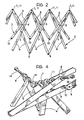
- the arm therefore has three longitudinal sides, each of which includes a first and a second kinematic pantograph chain indicated 2, 3 respectively in Figure 2.
- the first kinematic pantograph chain 2 is constituted by a plurality of rods 4 of equal length which are articulated together in pairs centrally about articulation axes 5, by means of rotary couplings, so as to constitute a series of aligned X-shaped elements. These X-shaped elements are themselves connected together about articulation axes 6, 7 at the ends of the rods 4 by rotary couplings.
- the second kinematic pantograph chain 3 is constituted by a plurality of rods 8 articulated together in pairs centrally about articulation axes 9, by means of rotary couplings, so as to define a series of aligned X-shaped elements which, in their turn, are connected together about articulation axes 10, 11 at the ends of the rods 8 by rotary couplings.
- the rods 8 are shorter than the rods 4. More particularly, in the embodiment illustrated in the drawings, the ratio between the length I d of the rods 4 and the length 1 m of the rods 8 is equal to
- the arm 1 can adopt any configuration between the fully extended configuration illustrated in Figure 1 and the fully retracted condition illustrated in Figure 3.
- the rods 8 are located substantially parallel to each other so as to define three longitudinal struts 12 which give the arm a high degree of flexural strength.
- the rods 4 are located in pairs perpendicular to each other so as to constitute diagonals 13 connecting the struts.
- the arm according to the invention has a high value for the ratio between its respective lengths in its fully extended condition and its fully retracted condition.
- the arm according to the invention has a high degree of rigidity in any configuration between its fully retracted condition and its fully extended condition.
- the arm according to the invention has a unique degree of freedom in that its geometry is univocally defined once the configuration of any of the X-shaped elements of any one of the kinematic chains constituting the structure of the arm is defined. It follows that the movement of the arm may be controlled by acting on any one part of its structure and more particularly on the basal end of the arm.
- the control means for moving the arm may be constituted by an actuator of any known type and none is illustrated in the appended drawings both to render the latter clearer and simpler to understand and because such control means do not fall within the scope of the present invention.
- Figure 4 illustrates, purely by way of example, the details of an articulated connection between the rods converging in a single zone of the structure constituting the arm.
- On one side of the arm are two rods 4 converging towards their respective articulation 6, while on the other side are located two other rods 4 which also converge towards their respective articulation 7 and two rods 8 which converge towards the respective articulation 11 coinciding with the articulation 7.
- the rods in the particular embodiment illustrated are articulated at two pins 14 at an angle of 120° to each other and carried by a single connecting block 15.
- a further advantage of the arm according to the invention lies in the fact that all the articulations forming part thereof can be achieved by rotary couplings (that is, with single axes of articulation) which simplifies the manufacture and assembly considerably.
- the first example relates to an arm constituted by tubular rods of aluminium alloy.
- the data relating to the X-shaped elements constituting the second kinematic chain 3 forming part of each of the three sides of the arm are as follows:
- the characteristics of the rods 4 constituting the first kinematic chain 2 are as follows:
- each rod 4 is identical to the corresponding diameters of each rod 8.
- the number of X-shaped elements in the first kinematic chain 2 is obviously equal to the number of X-shaped elements in the second kinematic chain 3.
- This example relates to an arm which is structurally similar to the preceding one, with the difference that the rods are made of steel.
- the length of the arm in the fully extended condition is still 100 m, while in the fully retracted condition is 1.515 m.
- the point load of each rod 8 is 8527 N (1328 N in the case of Example 1).
Landscapes
- Engineering & Computer Science (AREA)
- Remote Sensing (AREA)
- Aviation & Aerospace Engineering (AREA)
- Steering-Linkage Mechanisms And Four-Wheel Steering (AREA)
- Jib Cranes (AREA)
- Transmission Devices (AREA)
- Current-Collector Devices For Electrically Propelled Vehicles (AREA)
- Body Structure For Vehicles (AREA)
- Vehicle Body Suspensions (AREA)
Claims (3)
Priority Applications (1)
| Application Number | Priority Date | Filing Date | Title |
|---|---|---|---|
| AT84830257T ATE26682T1 (de) | 1983-09-30 | 1984-09-24 | Ausdehnbarer arm insbesondere fuer weltraumfaehre oder -fahrzeug. |
Applications Claiming Priority (2)
| Application Number | Priority Date | Filing Date | Title |
|---|---|---|---|
| IT68013/83A IT1162948B (it) | 1983-09-30 | 1983-09-30 | Braccio estensibile particolarmente per veicoli o moduli spaziali |
| IT6801383 | 1983-09-30 |
Publications (3)
| Publication Number | Publication Date |
|---|---|
| EP0136985A2 EP0136985A2 (fr) | 1985-04-10 |
| EP0136985A3 EP0136985A3 (en) | 1985-07-10 |
| EP0136985B1 true EP0136985B1 (fr) | 1987-04-22 |
Family
ID=11307187
Family Applications (1)
| Application Number | Title | Priority Date | Filing Date |
|---|---|---|---|
| EP84830257A Expired EP0136985B1 (fr) | 1983-09-30 | 1984-09-24 | Bras extensible, en particulier pour modules ou véhicules spatiaux |
Country Status (5)
| Country | Link |
|---|---|
| US (1) | US4557083A (fr) |
| EP (1) | EP0136985B1 (fr) |
| AT (1) | ATE26682T1 (fr) |
| DE (1) | DE3463242D1 (fr) |
| IT (1) | IT1162948B (fr) |
Families Citing this family (30)
| Publication number | Priority date | Publication date | Assignee | Title |
|---|---|---|---|---|
| US5167100A (en) * | 1986-06-12 | 1992-12-01 | Anandasivam Krishnapillai | Deployable structures |
| US5038532A (en) * | 1989-10-10 | 1991-08-13 | University Of New Mexico | Deployable spatial structure |
| WO1995021350A1 (fr) * | 1994-02-07 | 1995-08-10 | Aleph Co., Ltd. | Construction a cadre |
| US5701713A (en) * | 1996-03-29 | 1997-12-30 | Silver; Daniel J. | Adjustable truss |
| US5857648A (en) * | 1997-01-28 | 1999-01-12 | Trw Inc. | Precision deployable boom assembly |
| RU2167789C1 (ru) * | 2000-04-24 | 2001-05-27 | Открытое акционерное общество "Ракетно-космическая корпорация "Энергия" им. С.П. Королева" | Трансформируемая конструкция |
| US7694486B2 (en) * | 2003-12-12 | 2010-04-13 | Alliant Techsystems Inc. | Deployable truss having second order augmentation |
| US20060118675A1 (en) * | 2004-12-07 | 2006-06-08 | Tidwell John Z | Transformable fluid foil with pivoting spars and ribs |
| US8042305B2 (en) * | 2005-03-15 | 2011-10-25 | Alliant Techsystems Inc. | Deployable structural assemblies, systems for deploying such structural assemblies |
| US7694465B2 (en) * | 2005-04-08 | 2010-04-13 | Alliant Techsystems Inc. | Deployable structural assemblies, systems for deploying such structural assemblies and related methods |
| US20080283670A1 (en) * | 2006-12-13 | 2008-11-20 | Thomas Jeffrey Harvey | K-truss deployable boom system |
| FR2937186B1 (fr) * | 2008-10-14 | 2010-11-12 | Centre Nat Etd Spatiales | Structure deployable et systeme antennaire a membranes comprenant une telle structure. |
| US8371088B2 (en) * | 2009-04-23 | 2013-02-12 | Donald V. Merrifield | Deployable truss with integral folding panels |
| ES2368639B1 (es) * | 2009-08-21 | 2012-10-02 | Rodrigo García González | Sistema estructural desplegable fractal. |
| US9550584B1 (en) * | 2010-09-30 | 2017-01-24 | MMA Design, LLC | Deployable thin membrane apparatus |
| US9249565B2 (en) * | 2011-12-07 | 2016-02-02 | Cpi Technologies, Llc | Deployable truss with orthogonally-hinged primary chords |
| WO2013086422A1 (fr) * | 2011-12-07 | 2013-06-13 | Merrifield Donald V | Armature en mesure de se déployer ayant des membrures primaires à articulations perpendiculaires |
| RU2541611C2 (ru) * | 2013-04-16 | 2015-02-20 | Открытое акционерное общество "Информационные спутниковые системы" имени академика М.Ф. Решетнёва" | Трансформируемая конструкция |
| GB2517920B (en) * | 2013-09-04 | 2016-05-18 | Ten Fold Eng Ltd | Apparatus for converting motion |
| AU2015252101A1 (en) * | 2014-11-26 | 2016-06-09 | Illinois Tool Works Inc. | Trusses for use in building construction and methods of installing same |
| US9828772B2 (en) * | 2015-06-11 | 2017-11-28 | L'garde, Inc. | Truss designs, materials, and fabrication |
| EP3353855B1 (fr) | 2015-09-25 | 2021-07-07 | MMA Design, LLC | Structure déployable destinée à être utilisée dans l'établissement d'une antenne à réseau réflecteur |
| JP7011115B2 (ja) | 2016-02-29 | 2022-02-10 | ルギャルド,インク. | 折り畳み可能なrf膜アンテナ |
| WO2017192200A1 (fr) | 2016-05-05 | 2017-11-09 | The Research Foundation For The State Unversity Of New York | Compositions pour le traitement de la parodontite et de l'accumulation de calculs dentaires |
| JP7605632B2 (ja) | 2018-02-15 | 2024-12-24 | ルギャルド,インク. | スペースデブリ係合および軌道離脱システム |
| JP6860224B2 (ja) * | 2019-03-04 | 2021-04-14 | 株式会社不二宮製作所 | 伸縮アーム |
| EP4022713A4 (fr) | 2019-08-30 | 2023-08-23 | L'garde, Inc. | Antenne compactable pour communications par satellite |
| EP4110698A4 (fr) | 2020-02-24 | 2024-02-14 | L'garde, Inc. | Ensemble de raccordement |
| US11973258B2 (en) | 2020-10-14 | 2024-04-30 | L'garde, Inc. | Compactable structures for deployment in space |
| US12549126B2 (en) | 2021-11-12 | 2026-02-10 | L'garde, Inc. | Lightweight, low stow volume, deployable solar concentrator for space applications |
Family Cites Families (8)
| Publication number | Priority date | Publication date | Assignee | Title |
|---|---|---|---|---|
| US396175A (en) * | 1889-01-15 | Fire-escape | ||
| US3375624A (en) * | 1965-10-11 | 1968-04-02 | Kenneth Millhiser | Structural member |
| US3381923A (en) * | 1965-12-27 | 1968-05-07 | Fairchild Hiller Corp | Deployable structure |
| US3496687A (en) * | 1967-03-22 | 1970-02-24 | North American Rockwell | Extensible structure |
| US3509576A (en) * | 1967-12-04 | 1970-04-28 | Lockheed Aircraft Corp | Collapsible parabolic antenna formed of a series of truncated fabric cones |
| US4126974A (en) * | 1977-11-17 | 1978-11-28 | Hardin Gary L | Expandable beam structure |
| DE2941170C2 (de) * | 1979-10-11 | 1984-02-23 | Messerschmitt-Bölkow-Blohm GmbH, 8000 München | Durch Zwangskopplung auseinander- und zusammenfaltbare flächige Struktur |
| DE3222475A1 (de) * | 1981-06-19 | 1983-01-27 | British Aerospace Public Ltd. Co., London | Ausfahrbarer mastaufbau |
-
1983
- 1983-09-30 IT IT68013/83A patent/IT1162948B/it active
-
1984
- 1984-09-24 AT AT84830257T patent/ATE26682T1/de active
- 1984-09-24 EP EP84830257A patent/EP0136985B1/fr not_active Expired
- 1984-09-24 DE DE8484830257T patent/DE3463242D1/de not_active Expired
- 1984-09-26 US US06/654,454 patent/US4557083A/en not_active Expired - Fee Related
Also Published As
| Publication number | Publication date |
|---|---|
| EP0136985A2 (fr) | 1985-04-10 |
| ATE26682T1 (de) | 1987-05-15 |
| IT8368013A0 (it) | 1983-09-30 |
| US4557083A (en) | 1985-12-10 |
| EP0136985A3 (en) | 1985-07-10 |
| DE3463242D1 (en) | 1987-05-27 |
| IT1162948B (it) | 1987-04-01 |
Similar Documents
| Publication | Publication Date | Title |
|---|---|---|
| EP0136985B1 (fr) | Bras extensible, en particulier pour modules ou véhicules spatiaux | |
| EP0408826B1 (fr) | Mât extensible | |
| EP0209083B1 (fr) | Structure extensible | |
| EP0210776A2 (fr) | Ensemble de fermes repliable et charpentes construites par combinaison de tels ensembles | |
| US4433700A (en) | Panel structure | |
| US4334391A (en) | Redundant deployable lattice column | |
| CA2285980A1 (fr) | Structure tridimensionnelle a treillis isometrique | |
| EP0390149A1 (fr) | Treillis repliable | |
| JPS6124741A (ja) | 関節型伸展トラスビ−ム | |
| AU638469B2 (en) | Bidimensional truss structure, particularly support for overhead electric energy transmission lines | |
| CA2044286A1 (fr) | Engin articule autopropulse a verins telescopiques pour l'inspection de canalisations | |
| US3360255A (en) | Universal flexure unit | |
| US20130305867A1 (en) | Tension Stiffened and Tendon Actuated Manipulator and a Hinge for Use Therein | |
| EP0159486A2 (fr) | Poutre en treillis et procédé de montage | |
| ATE81378T1 (de) | Knoten-stab-system. | |
| CN211196627U (zh) | 一种八旋翼无人机 | |
| EP0829287A3 (fr) | Jouet roulant | |
| US5145075A (en) | Boom point construction | |
| US4644628A (en) | Method of truss structure construction | |
| Padmanabhan et al. | VGT-based gimbals: practical construction and general theory | |
| JP7266868B2 (ja) | テンセグリティ構造を有する構造体、建築部材および建築物 | |
| ATE62043T1 (de) | Bewehrung fuer stahlbetonkonstruktionen. | |
| JP2618879B2 (ja) | 伸長構造物 | |
| SU796168A1 (ru) | Траверса | |
| SU1174256A1 (ru) | Манипул тор модульного типа |
Legal Events
| Date | Code | Title | Description |
|---|---|---|---|
| PUAI | Public reference made under article 153(3) epc to a published international application that has entered the european phase |
Free format text: ORIGINAL CODE: 0009012 |
|
| AK | Designated contracting states |
Designated state(s): AT BE CH DE FR GB IT LI LU NL SE |
|
| PUAL | Search report despatched |
Free format text: ORIGINAL CODE: 0009013 |
|
| AK | Designated contracting states |
Designated state(s): AT BE CH DE FR GB IT LI LU NL SE |
|
| 17P | Request for examination filed |
Effective date: 19851115 |
|
| 17Q | First examination report despatched |
Effective date: 19860710 |
|
| GRAA | (expected) grant |
Free format text: ORIGINAL CODE: 0009210 |
|
| AK | Designated contracting states |
Kind code of ref document: B1 Designated state(s): AT BE CH DE FR GB IT LI LU NL SE |
|
| REF | Corresponds to: |
Ref document number: 26682 Country of ref document: AT Date of ref document: 19870515 Kind code of ref document: T |
|
| ITF | It: translation for a ep patent filed | ||
| RAP2 | Party data changed (patent owner data changed or rights of a patent transferred) |
Owner name: AERITALIA - SOCIETA AEROSPAZIALE ITALIANA - P.A. |
|
| ET | Fr: translation filed | ||
| REF | Corresponds to: |
Ref document number: 3463242 Country of ref document: DE Date of ref document: 19870527 |
|
| PG25 | Lapsed in a contracting state [announced via postgrant information from national office to epo] |
Ref country code: LU Free format text: LAPSE BECAUSE OF NON-PAYMENT OF DUE FEES Effective date: 19870930 |
|
| PGFP | Annual fee paid to national office [announced via postgrant information from national office to epo] |
Ref country code: NL Payment date: 19870930 Year of fee payment: 4 |
|
| BECN | Be: change of holder's name |
Effective date: 19870422 |
|
| PLBE | No opposition filed within time limit |
Free format text: ORIGINAL CODE: 0009261 |
|
| STAA | Information on the status of an ep patent application or granted ep patent |
Free format text: STATUS: NO OPPOSITION FILED WITHIN TIME LIMIT |
|
| 26N | No opposition filed | ||
| PG25 | Lapsed in a contracting state [announced via postgrant information from national office to epo] |
Ref country code: GB Effective date: 19880924 Ref country code: AT Effective date: 19880924 |
|
| PG25 | Lapsed in a contracting state [announced via postgrant information from national office to epo] |
Ref country code: SE Effective date: 19880925 |
|
| PG25 | Lapsed in a contracting state [announced via postgrant information from national office to epo] |
Ref country code: LI Effective date: 19880930 Ref country code: CH Effective date: 19880930 Ref country code: BE Effective date: 19880930 |
|
| BERE | Be: lapsed |
Owner name: AERITALIA - SOCIETA AEROSPAZIALE ITALIANA - P.A. Effective date: 19880930 |
|
| PG25 | Lapsed in a contracting state [announced via postgrant information from national office to epo] |
Ref country code: NL Effective date: 19890401 |
|
| NLV4 | Nl: lapsed or anulled due to non-payment of the annual fee | ||
| PG25 | Lapsed in a contracting state [announced via postgrant information from national office to epo] |
Ref country code: FR Free format text: LAPSE BECAUSE OF NON-PAYMENT OF DUE FEES Effective date: 19890531 |
|
| REG | Reference to a national code |
Ref country code: CH Ref legal event code: PL |
|
| GBPC | Gb: european patent ceased through non-payment of renewal fee | ||
| PG25 | Lapsed in a contracting state [announced via postgrant information from national office to epo] |
Ref country code: DE Effective date: 19890601 |
|
| REG | Reference to a national code |
Ref country code: FR Ref legal event code: ST |
|
| EUG | Se: european patent has lapsed |
Ref document number: 84830257.6 Effective date: 19890712 |