EP0137096A2 - Montage élastique des extrémités de ressorts à lame pour véhicules routiers et de chemin de fer - Google Patents
Montage élastique des extrémités de ressorts à lame pour véhicules routiers et de chemin de fer Download PDFInfo
- Publication number
- EP0137096A2 EP0137096A2 EP84103472A EP84103472A EP0137096A2 EP 0137096 A2 EP0137096 A2 EP 0137096A2 EP 84103472 A EP84103472 A EP 84103472A EP 84103472 A EP84103472 A EP 84103472A EP 0137096 A2 EP0137096 A2 EP 0137096A2
- Authority
- EP
- European Patent Office
- Prior art keywords
- leaf spring
- rubber
- shells
- cylindrical body
- metal
- Prior art date
- Legal status (The legal status is an assumption and is not a legal conclusion. Google has not performed a legal analysis and makes no representation as to the accuracy of the status listed.)
- Granted
Links
Images
Classifications
-
- F—MECHANICAL ENGINEERING; LIGHTING; HEATING; WEAPONS; BLASTING
- F16—ENGINEERING ELEMENTS AND UNITS; GENERAL MEASURES FOR PRODUCING AND MAINTAINING EFFECTIVE FUNCTIONING OF MACHINES OR INSTALLATIONS; THERMAL INSULATION IN GENERAL
- F16F—SPRINGS; SHOCK-ABSORBERS; MEANS FOR DAMPING VIBRATION
- F16F1/00—Springs
- F16F1/02—Springs made of steel or other material having low internal friction; Wound, torsion, leaf, cup, ring or the like springs, the material of the spring not being relevant
- F16F1/18—Leaf springs
- F16F1/26—Attachments or mountings
- F16F1/30—Attachments or mountings comprising intermediate pieces made of rubber or similar elastic material
-
- B—PERFORMING OPERATIONS; TRANSPORTING
- B60—VEHICLES IN GENERAL
- B60G—VEHICLE SUSPENSION ARRANGEMENTS
- B60G11/00—Resilient suspensions characterised by arrangement, location or kind of springs
- B60G11/02—Resilient suspensions characterised by arrangement, location or kind of springs having leaf springs only
- B60G11/10—Resilient suspensions characterised by arrangement, location or kind of springs having leaf springs only characterised by means specially adapted for attaching the spring to axle or sprung part of the vehicle
- B60G11/107—Sliding or rolling mountings
-
- B—PERFORMING OPERATIONS; TRANSPORTING
- B60—VEHICLES IN GENERAL
- B60G—VEHICLE SUSPENSION ARRANGEMENTS
- B60G11/00—Resilient suspensions characterised by arrangement, location or kind of springs
- B60G11/32—Resilient suspensions characterised by arrangement, location or kind of springs having springs of different kinds
- B60G11/34—Resilient suspensions characterised by arrangement, location or kind of springs having springs of different kinds including leaf springs
- B60G11/38—Resilient suspensions characterised by arrangement, location or kind of springs having springs of different kinds including leaf springs and also rubber springs
- B60G11/42—Resilient suspensions characterised by arrangement, location or kind of springs having springs of different kinds including leaf springs and also rubber springs the rubber springs being attached to sprung part of the vehicle
Definitions
- the invention relates to an elastic mounting of leaf spring ends for road and rail vehicles according to the preamble of claim 1.
- a rubber or rubber-metal bushing is pressed into an eye rolled at the end of the leaf spring, the inner tube of which is non-positively fastened to the fastening bolt of the spring.
- This construction is to be incorporated without wear in a position which lies in the order of ⁇ 20 0 angle changes of the spring end only by molecular deformation in the rubber, wherein only a desirable small restoring torque is caused.
- such an embodiment is only useful for passenger cars and very light trucks, because leaf spring eyes can only be rolled up with a limited diameter and therefore the pressed-in rubber-metal bushings can only have a small diameter and can therefore only absorb small radial forces.
- the bushing In order to be able to absorb the considerably larger vertical and radial loads acting in the direction of travel in a heavy truck, the bushing would have to have a considerably larger diameter, so that a rolled eye at the end of the spring leaf can no longer be used.
- a rubber-metal bushing is unable to absorb the forces resulting from side forces of the leaf spring, for example when cornering.
- the rolled eye is widened by the radial rubber pressure and is no longer tight, which can lead to rubber abrasion and rapid wear.
- Bearings of leaf spring ends are also known, in which a spring end is clamped between two flat cuboid rubber pieces.
- the hardness of the spring elements is neither sufficient in the direction of travel to absorb braking and starting forces nor for lateral forces when cornering, unless additional elements are used.
- the bearing is too soft in the leaf spring plane and therefore insufficient for good axis guidance.
- this embodiment has undesirably high restoring moments in the case of angular deflections of the leaf spring ends, which inevitably occur during compression and rebound.
- the object of the invention is to provide a mounting for leaf spring ends for road and rail vehicles which absorbs braking and starting forces as well as lateral forces when cornering, is largely wear-free and is also suitable for heavy vehicles.
- This cylindrical body is to be enclosed by a rubber-metal bushing provided with a slot for the passage of the spring or two rubber-metal half-shells, the rubber-metal bushing or the rubber-metal half-shells having surfaces worked on them on the end face, for the most part cover the preferably flat-conical end faces of the cylindrical body.
- the thus formed, also cylindrical body should be inserted into two metal bearing shells forming the outer housing, which are clamped together radially for the force-fitting fastening of the rubber-metal half shells.
- the leaf spring is mounted in a cylindrical or barrel-shaped, preferably metallic body, this can be surrounded on all sides, in particular also in the direction of travel and the lateral directions, by a rubber-metal bush or the rubber-metal half-shells.
- This advantageously leads to radial and lateral forces, in particular forces when starting and braking and lateral forces when cornering, being absorbed relatively rigidly by the bearing via the rubber which is then subjected to pressure for good axis guidance.
- Angular deflections of the leaf spring are advantageously taken up by the bearing in the desired manner with a relatively small restoring torque.
- Another advantage is that the inner surfaces of the bearing shells, which are preferably made of gray cast iron, do not have to be reworked.
- the rubber introduced under pressure preload lies against the inside of the bearing shells and is held there by frictional adhesion, so that movements in the bearing are absorbed by the rubber without wear due to molecular deformation.
- the cylindrical body is formed from two concentric cylinder halves made of metal or plastic placed on the leaf spring, the radii of which have their center in the center of the leaf spring.
- the leaf spring can be connected to the cylinder halves for fixing them, for example by a bolt, or can be displaceable between the cylinder halves at the other end.
- the cylindrical body at the leaf spring end can be formed by a rolled eye.
- the eye is not used here as an outer bearing shell, but is surrounded by the rubber-metal half-shells or a rubber-metal bushing and clamped in outer bearing shells. This is a simple and inexpensive embodiment, in particular for the leaf spring end that is to be fixed in the direction of travel.
- the storage according to the invention can also be carried out with two superimposed and mutually supporting leaf spring ends.
- the axes of the semi-cylindrical bodies can here on the parting plane between them and the outer Blattfe the surfaces.
- the leaf spring ends facing bearing surfaces of the semi-cylindrical body with sliding layers and the leaf spring ends between them slidably, it is achieved that the leaf spring ends are displaceable to compensate for length in compression in the camp.
- a certain length compensation for smaller spring deflections is absorbed by the bearing due to the elasticity of the rubber; the leaf spring end is only moved in the bearing with longer spring deflections or a large static preload.
- the bearing surfaces provided with a sliding layer should have a slight curvature. This ensures that the spring ends are largely moved flat on the sliding layer and not on a transverse edge of the semi-cylindrical body.
- Claim 8 specifies the levels in which the outer housing shells can be appropriately divided.
- the shape of the bearing parts must be such that a compressive stress is applied to the rubber metal parts when the housing shells are clamped together.
- the half cylinder in cross section also have an approximately elliptical shape or spindle shape.
- the storage properties can be changed within certain limits and adapted to the respective requirements.
- a spring end is to be firmly connected to the corresponding cylindrical body or the cylindrical body is formed by an eye.
- This spring end of the leaf spring is fixed in the direction of travel and can only perform longitudinal movements in the bearing and within small limits in accordance with the elasticity of the rubber.
- the other end of the spring should be slidably mounted between two semi-cylindrical bodies and a length compensation of the spring should be made possible with longer spring travel.
- An advantageous embodiment of the rubber-metal half-shells has the content of claim 12.
- thin-walled metal sheets should be vulcanized onto the edges on the inner and outer surface. These metal sheets are to be supported in the clamped state on the outer bearing shells, the inner half cylinders or directly on the leaf spring end. As a result, part of the rubber volume is displaced and a high contact pressure is exerted by the rubber on the outer housing and the cylindrical body, which causes the frictional adhesion.
- the vulcanized sheet metal strips largely prevent the rubber from stretching under load.
- the displacement of the sheet metal strips in the direction of the rubber body when the bearing shells are clamped together is dimensioned such that the rubber-metal half-shells are pressed against the bearing shells or the cylindrical body in an immovable manner even under the greatest expected loads.
- the rubber-metal half-shells are inserted into the bearing shells and then inserted without effort spanned together. Because of the small mass of the metal sheet strips, the vulcanization times are short and the adhesive strength values are particularly good.
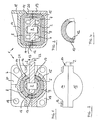
- a bolt 3 projects through a hole in a leaf spring end 2 on both sides.
- Semi-cylindrical bodies 4, 5 are placed on the leaf spring end 2 on both sides.
- the semi-cylindrical bodies 4, 5 contain bores in which the bolt 3 is inserted.
- the cylinder halves 4, 5 contain recesses 6, 7 (FIG. 2) and extend at their end faces over the leaf spring end 2.
- the folded cylinder halves 4, 5 thus form a cylinder piece into which the leaf spring end 2 is inserted through a slot on the cylinder jacket and inside the cylinder piece is held by the bolt 3.
- the cylinder halves 4, 5 are surrounded by rubber-metal half shells 8, 9, which also enclose the end faces of the cylinder halves 4, 5 with surfaces 10, 11 machined on the end face.
- rubber-metal half-shells At the edges of the rubber-metal half-shells, thin-walled sheet metal strips 12, 13 are vulcanized on the inside and outside thereof.
- the rubber-metal half-shells are clamped between two bearing shells 14, 15.
- the bearing shells 14, 15 are divided in the horizontal plane and held together by screw connections 16, 17. When screwed together, they contain a cylindrical receiving eye for the rubber-metal half-shells 8, 9, which has a horizontally running transverse slot 17.
- the transverse slot 17 is dimensioned such that the edge of the transverse slot is not reached by the leaf spring even with the largest spring travel to be expected.
- a vertical support plate 19, 20 provided with bores 18 is molded onto the bearing shells 14, 15.
- the bearing shells 14, 15 and the support plate 19, 20 form the bearing block for the leaf spring 2, which can be screwed through the holes 18 to a (not shown) side member of a vehicle.
- the sheet metal strips 12, 13 of the two rubber-metal half shells lie against one another in the clamped state. Only in the area of the transverse slot 17 do the inner sheet metal strips 12 rest directly on the leaf spring end 2, while the outer sheet metal strips 12 are supported on a projection 21 on the inside of the bearing shells 14, 15.
- FIG. 3 shows a view of the closed bearing 1 according to FIG. 1, from which it can be seen that the bearing forms a closed unit except for the transverse slot 17 for the leaf spring 2.
- FIG. 4 shows a rubber-metal half-shell 8 in a section according to FIG. 1 in the unloaded state.
- the leaf spring bearing 1 shown has the following function: With an angular deflection (arrow 22; approx. Max. ⁇ 20 °), the rubber in the rubber-metal half-shells 8, 9 is subjected to thrust, as a result of which only relatively small restoring moments occur. Lateral forces and forces in the direction of travel, however, largely burden the cylinder halves 4, 5 surrounding rubber on pressure, so that these forces are absorbed only with slight deflections in the bearing 1, which leads to a desired good axis guidance.
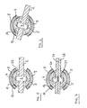
- Fig. 5 shows an embodiment in which the leaf spring end 2 is inserted through a continuous slot between the cylinder halves 4, 5.
- the cylinder halves 4, 5 are also held with a bolt 3.
- the inner sheet metal strip 12 is supported here on a projection 23 of the half cylinders 4, 5.
- the sheet metal strip 12 could also extend here to the leaf spring end 2; it is only essential that the sheet metal strip 12 is fixed against displacement towards the outside of the rubber-metal half-shell.
- the outer sheet metal strip 13 can be supported here on outer bearing shells (not shown here) in a manner similar to that shown in FIG. 1.
- FIG. 6 shows the bearing according to FIG. 5 in the spring-loaded state (the bearing shells of the outer housing not being drawn here either for the sake of clarity). From this drawing it can be seen that the rubber of the rubber-metal half-shells is subjected to a thrust load on thrust.
- FIG. 7 shows a similar embodiment to that shown in FIGS. 5 and 6, except that here two leaf spring ends 24, 25 lying on top of one another and supporting one another are held in the bearing.
- the bolt 3 is divided here into two bolts 26, 27 along the contact surface of the leaf spring ends 24, 25. As a result, the two leaf spring ends 24, 25 are not held together, but can still move slightly against each other when deflected.
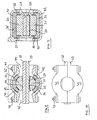
- the leaf spring end 2 was ge using a bolt 3 in the camp hold. With larger spring travel, however, the leaf spring is deflected so far that a length or distance compensation between the two bearing points is required.
- Two cylinder halves 30, 31 are placed on two adjacent leaf spring ends 28, 29.
- the cylinder halves 30, 31 encompass the leaf spring ends 28, 29 on the end face. It could also (as shown in FIG. 9) be an entire cylinder in which a continuous slot is made for inserting the leaf spring ends 28, 29.
- the contact surfaces 32, 33 of the leaf spring ends 28, 29 in the cylinder halves 30, 31 have a slight curvature in the direction of the leaf spring ends.
- the lower contact surface 33 is provided with a sliding layer 34.
- Rubber-metal half-shells 35, 36 are placed on the cylinder halves 30, 31 and extend over the end faces of the cylinder halves 30, 31 with surfaces 37, 38 machined on the end face. Inner and outer sheet metal strips 39, 40 are secured against being displaced by rubber expansion at shoulders on the cylinder halves 30, 31 and on bearing shells 41, 42.
- the rubber-metal half shells are enclosed under prestress by the bearing shells 41, 42, which are clamped together with screw connections 43.
- a vertical claw 44 is formed on the upper bearing shell 41, with which the bearing can be attached to a vehicle.
- the bearing shells 41, 42 are designed such that slots 44, 45 are formed in the horizontal transverse direction, through which the leaf spring ends 28, 29 are guided and which are dimensioned so large that they do not limit the maximum deflection of the leaf spring ends.
- FIG. 10 shows a top view of the bearing according to FIG. 8, in which the frontal design of the bearing shells 41, 42 can be seen.
- the subject of the application provides storage for leaf spring ends which, with a small restoring torque, is also suitable for heavy vehicles, which absorbs braking and starting forces as well as lateral forces when cornering for good axle guidance and is largely wear-free.
Landscapes
- Engineering & Computer Science (AREA)
- Mechanical Engineering (AREA)
- General Engineering & Computer Science (AREA)
- Springs (AREA)
- Vehicle Body Suspensions (AREA)
- Support Of The Bearing (AREA)
Priority Applications (1)
| Application Number | Priority Date | Filing Date | Title |
|---|---|---|---|
| AT84103472T ATE37166T1 (de) | 1983-09-13 | 1984-03-29 | Elastische lagerung von blattfederenden fuer strassen- und schienenfahrzeuge. |
Applications Claiming Priority (2)
| Application Number | Priority Date | Filing Date | Title |
|---|---|---|---|
| DE3332952A DE3332952A1 (de) | 1983-09-13 | 1983-09-13 | Elastische lagerung von blattfederenden fuer strassen- und schienenfahrzeuge |
| DE3332952 | 1983-09-13 |
Publications (3)
| Publication Number | Publication Date |
|---|---|
| EP0137096A2 true EP0137096A2 (fr) | 1985-04-17 |
| EP0137096A3 EP0137096A3 (en) | 1985-12-18 |
| EP0137096B1 EP0137096B1 (fr) | 1988-09-14 |
Family
ID=6208914
Family Applications (1)
| Application Number | Title | Priority Date | Filing Date |
|---|---|---|---|
| EP84103472A Expired EP0137096B1 (fr) | 1983-09-13 | 1984-03-29 | Montage élastique des extrémités de ressorts à lame pour véhicules routiers et de chemin de fer |
Country Status (4)
| Country | Link |
|---|---|
| EP (1) | EP0137096B1 (fr) |
| JP (1) | JPS6060340A (fr) |
| AT (1) | ATE37166T1 (fr) |
| DE (2) | DE3332952A1 (fr) |
Cited By (8)
| Publication number | Priority date | Publication date | Assignee | Title |
|---|---|---|---|---|
| WO1986002886A1 (fr) * | 1984-11-07 | 1986-05-22 | Gkn Technology Limited | Montages pour ressorts |
| EP0321178A1 (fr) * | 1987-12-16 | 1989-06-21 | Crane Fruehauf Limited | Mécanisme d'articulation |
| EP0359599A1 (fr) * | 1988-09-02 | 1990-03-21 | RENAULT VEHICULES INDUSTRIELS Société Anonyme dite: | Dispositif de fixation d'un ressort à lame en matériau composite |
| WO1995026887A1 (fr) * | 1994-03-31 | 1995-10-12 | Detroit Steel Products Co., Inc. | Systeme de suspension pour vehicule |
| EP0763438A3 (fr) * | 1995-09-13 | 1998-04-15 | Dr.Ing.h.c. F. Porsche Aktiengesellschaft | Suspension de roue d'un véhicule automobile avec un ressort à lame guidant la roue |
| US6206407B1 (en) | 1998-12-18 | 2001-03-27 | Freightliner Llc | Vehicle suspension system |
| EP0993971A3 (fr) * | 1998-10-15 | 2001-07-18 | Lord Corporation | Palier de pivotement pour ressort à lames et ensemble à pilote réglable |
| US6361026B2 (en) * | 1994-03-31 | 2002-03-26 | Detroit Steel Products Co., Inc. | Vehicle suspension system |
Families Citing this family (3)
| Publication number | Priority date | Publication date | Assignee | Title |
|---|---|---|---|---|
| JPH0643552Y2 (ja) * | 1986-02-14 | 1994-11-14 | トヨタ自動車株式会社 | リーフスプリングの支持装置 |
| CN108787925A (zh) * | 2018-06-22 | 2018-11-13 | 东莞市联洲知识产权运营管理有限公司 | 一种冲压模具新型弹料装置 |
| CN108787677A (zh) * | 2018-06-22 | 2018-11-13 | 东莞市联洲知识产权运营管理有限公司 | 一种用于模具表面净化的清洗装置 |
Family Cites Families (8)
| Publication number | Priority date | Publication date | Assignee | Title |
|---|---|---|---|---|
| US1789725A (en) * | 1926-06-01 | 1931-01-20 | Inland Mfg Co | Rubber spring shackle |
| US1825352A (en) * | 1929-10-25 | 1931-09-29 | Gen Motors Corp | Rubber spring shackle |
| US2635869A (en) * | 1949-12-19 | 1953-04-21 | Eight Point Trailer Corp | Vehicle leaf spring mounting |
| US2831674A (en) * | 1950-12-27 | 1958-04-22 | Pacific Car & Foundry Co | Spring suspension |
| DE1123572B (de) * | 1956-02-18 | 1962-02-08 | Lemfoerder Metallwarengesellsc | Gleitlager aus Kunststoff fuer Blattfederenden besonders fuer Kraftfahrzeug-Blattfedern |
| DE1480019C3 (de) * | 1964-12-02 | 1975-11-27 | Georg 7900 Ulm Sontheimer | Lagerung der aufbauseitigen Federenden von eine Radachse führenden Blattfedern für Kraftfahrzeuge |
| AT325431B (de) * | 1972-01-05 | 1975-10-27 | Joern Raoul Dipl Ing | Kugelgelenk |
| SE434623B (sv) * | 1980-12-22 | 1984-08-06 | Saab Scania Ab | Arrangemang for upphengning av ett i ett fordons fjedersystem ingaende bladfjederpaket |
-
1983
- 1983-09-13 DE DE3332952A patent/DE3332952A1/de not_active Withdrawn
-
1984
- 1984-03-29 DE DE8484103472T patent/DE3474009D1/de not_active Expired
- 1984-03-29 AT AT84103472T patent/ATE37166T1/de not_active IP Right Cessation
- 1984-03-29 EP EP84103472A patent/EP0137096B1/fr not_active Expired
- 1984-05-10 JP JP59094419A patent/JPS6060340A/ja active Pending
Cited By (11)
| Publication number | Priority date | Publication date | Assignee | Title |
|---|---|---|---|---|
| WO1986002886A1 (fr) * | 1984-11-07 | 1986-05-22 | Gkn Technology Limited | Montages pour ressorts |
| GB2191262A (en) * | 1984-11-07 | 1987-12-09 | Gkn Technology Ltd | Mountings for springs |
| EP0321178A1 (fr) * | 1987-12-16 | 1989-06-21 | Crane Fruehauf Limited | Mécanisme d'articulation |
| EP0359599A1 (fr) * | 1988-09-02 | 1990-03-21 | RENAULT VEHICULES INDUSTRIELS Société Anonyme dite: | Dispositif de fixation d'un ressort à lame en matériau composite |
| US5020824A (en) * | 1988-09-02 | 1991-06-04 | Renault Vehicules Industriels | Device for mounting a composite material leaf spring |
| WO1995026887A1 (fr) * | 1994-03-31 | 1995-10-12 | Detroit Steel Products Co., Inc. | Systeme de suspension pour vehicule |
| US6361026B2 (en) * | 1994-03-31 | 2002-03-26 | Detroit Steel Products Co., Inc. | Vehicle suspension system |
| EP0763438A3 (fr) * | 1995-09-13 | 1998-04-15 | Dr.Ing.h.c. F. Porsche Aktiengesellschaft | Suspension de roue d'un véhicule automobile avec un ressort à lame guidant la roue |
| US5826896A (en) * | 1995-09-13 | 1998-10-27 | Dr. Ing. H.C.F. Porsche Ag | Wheel suspension for a motor vehicle having a wheel guiding leaf spring |
| EP0993971A3 (fr) * | 1998-10-15 | 2001-07-18 | Lord Corporation | Palier de pivotement pour ressort à lames et ensemble à pilote réglable |
| US6206407B1 (en) | 1998-12-18 | 2001-03-27 | Freightliner Llc | Vehicle suspension system |
Also Published As
| Publication number | Publication date |
|---|---|
| JPS6060340A (ja) | 1985-04-06 |
| DE3474009D1 (en) | 1988-10-20 |
| EP0137096A3 (en) | 1985-12-18 |
| ATE37166T1 (de) | 1988-09-15 |
| EP0137096B1 (fr) | 1988-09-14 |
| DE3332952A1 (de) | 1985-03-28 |
Similar Documents
| Publication | Publication Date | Title |
|---|---|---|
| EP2470387B1 (fr) | Dispositif de montage pour un ressort à lame latéralement orienté | |
| DE2726676C2 (de) | Federelement zur elastischen Lagerung von Antriebs- oder sonstigen Aggregaten | |
| DE2656799C2 (de) | Verfahren zum Herstellen eines elastisch nachgiebigen Bauteiles sowie Verwendung der verfahrensgemäß hergestellten Bauteils als elastisches Schwenklager für einen Querlenker einer Fahrzeugachse | |
| DE1955308C3 (de) | Gummi-Metall-Gelenkbuchse | |
| DE69908714T2 (de) | Schraubendruckfeder für eine Fahrzeugradaufhängung | |
| DE102010054828A1 (de) | Servolenkung mit Spindeltrieb | |
| DE102009028893A1 (de) | Lagervorrichtung einer im Bereich einer Fahrzeugachse eines Fahrzeuges montierbaren Querblattfeder | |
| EP0132502A2 (fr) | Manchon du type à caoutchouc et métal, en particulier pour le montage d'un stabilisateur sur un véhicule à moteur | |
| DE68906588T2 (de) | Elastische lagerung mit hydraulischer versteifung. | |
| DE102007008325A1 (de) | Starrachse für ein Nutzkraftfahrzeug | |
| DE2703038C3 (de) | Vorspannbares Lagerelement | |
| EP0137096A2 (fr) | Montage élastique des extrémités de ressorts à lame pour véhicules routiers et de chemin de fer | |
| DE2739250C2 (de) | Scharniergelenk für ein Federgehänge | |
| DE2811034A1 (de) | Befestigungsauge, insbesondere fuer stossdaempfer | |
| DE10157933B4 (de) | Reaktionsstange | |
| DE2915811A1 (de) | Elastisches lager | |
| EP2186661B1 (fr) | Appui modifiable d'un ressort à boudin de compression ou analogue pour un véhicule automobile | |
| DE102017217598B4 (de) | Federbaugruppe | |
| DE4322304C1 (de) | Gelenklager, insbesondere für einen Achslenker eines Kraftfahrzeugs | |
| DE102020128606A1 (de) | Vorrichtung zum Lagern einer radführenden Querblattfeder eines Fahrzeuges | |
| DE69003328T2 (de) | Elastisches Gelenk, insbesondere für die Montage einer Kraftfahrzeugachse. | |
| DE69701947T2 (de) | Aufhängung von Auspuffanlagen | |
| DE102018200323A1 (de) | Blattfederanordnung für Kraftfahrzeuge | |
| DE1033047B (de) | Lagerung halbelliptischer Blattfedern an Kraftfahrzeugen | |
| DE102020106309A1 (de) | Riemenspanner |
Legal Events
| Date | Code | Title | Description |
|---|---|---|---|
| PUAI | Public reference made under article 153(3) epc to a published international application that has entered the european phase |
Free format text: ORIGINAL CODE: 0009012 |
|
| AK | Designated contracting states |
Designated state(s): AT DE FR GB IT |
|
| RIN1 | Information on inventor provided before grant (corrected) |
Inventor name: JOERN, RAOUL |
|
| ITCL | It: translation for ep claims filed |
Representative=s name: ING. C. GREGORJ S.P.A. |
|
| RTI1 | Title (correction) | ||
| EL | Fr: translation of claims filed | ||
| PUAL | Search report despatched |
Free format text: ORIGINAL CODE: 0009013 |
|
| AK | Designated contracting states |
Designated state(s): AT DE FR GB IT |
|
| RHK1 | Main classification (correction) |
Ipc: B60G 11/42 |
|
| 17P | Request for examination filed |
Effective date: 19860122 |
|
| 17Q | First examination report despatched |
Effective date: 19870128 |
|
| GRAA | (expected) grant |
Free format text: ORIGINAL CODE: 0009210 |
|
| AK | Designated contracting states |
Kind code of ref document: B1 Designated state(s): AT DE FR GB IT |
|
| REF | Corresponds to: |
Ref document number: 37166 Country of ref document: AT Date of ref document: 19880915 Kind code of ref document: T |
|
| REF | Corresponds to: |
Ref document number: 3474009 Country of ref document: DE Date of ref document: 19881020 |
|
| ITF | It: translation for a ep patent filed | ||
| GBT | Gb: translation of ep patent filed (gb section 77(6)(a)/1977) | ||
| ET | Fr: translation filed | ||
| PLBE | No opposition filed within time limit |
Free format text: ORIGINAL CODE: 0009261 |
|
| STAA | Information on the status of an ep patent application or granted ep patent |
Free format text: STATUS: NO OPPOSITION FILED WITHIN TIME LIMIT |
|
| 26N | No opposition filed | ||
| PGFP | Annual fee paid to national office [announced via postgrant information from national office to epo] |
Ref country code: FR Payment date: 19900328 Year of fee payment: 7 |
|
| PGFP | Annual fee paid to national office [announced via postgrant information from national office to epo] |
Ref country code: DE Payment date: 19900330 Year of fee payment: 7 Ref country code: AT Payment date: 19900330 Year of fee payment: 7 |
|
| ITTA | It: last paid annual fee | ||
| PGFP | Annual fee paid to national office [announced via postgrant information from national office to epo] |
Ref country code: GB Payment date: 19900331 Year of fee payment: 7 |
|
| PG25 | Lapsed in a contracting state [announced via postgrant information from national office to epo] |
Ref country code: GB Effective date: 19910329 Ref country code: AT Effective date: 19910329 |
|
| GBPC | Gb: european patent ceased through non-payment of renewal fee | ||
| PG25 | Lapsed in a contracting state [announced via postgrant information from national office to epo] |
Ref country code: FR Effective date: 19911129 |
|
| PG25 | Lapsed in a contracting state [announced via postgrant information from national office to epo] |
Ref country code: DE Effective date: 19920101 |
|
| REG | Reference to a national code |
Ref country code: FR Ref legal event code: ST |