EP0137141A1 - Appareil de détection de la concentration du toner - Google Patents
Appareil de détection de la concentration du toner Download PDFInfo
- Publication number
- EP0137141A1 EP0137141A1 EP84108110A EP84108110A EP0137141A1 EP 0137141 A1 EP0137141 A1 EP 0137141A1 EP 84108110 A EP84108110 A EP 84108110A EP 84108110 A EP84108110 A EP 84108110A EP 0137141 A1 EP0137141 A1 EP 0137141A1
- Authority
- EP
- European Patent Office
- Prior art keywords
- developer
- container
- detector container
- detector
- toner concentration
- Prior art date
- Legal status (The legal status is an assumption and is not a legal conclusion. Google has not performed a legal analysis and makes no representation as to the accuracy of the status listed.)
- Granted
Links
- 239000000203 mixture Substances 0.000 claims abstract description 7
- 230000003247 decreasing effect Effects 0.000 abstract 1
- 230000035699 permeability Effects 0.000 description 5
- 239000012530 fluid Substances 0.000 description 4
- 230000004907 flux Effects 0.000 description 4
- 230000002093 peripheral effect Effects 0.000 description 4
- 238000011160 research Methods 0.000 description 3
- 239000004020 conductor Substances 0.000 description 2
- 230000007547 defect Effects 0.000 description 2
- 230000002950 deficient Effects 0.000 description 2
- 239000002245 particle Substances 0.000 description 2
- 230000009467 reduction Effects 0.000 description 2
- 239000011347 resin Substances 0.000 description 2
- 229920005989 resin Polymers 0.000 description 2
- 238000007493 shaping process Methods 0.000 description 2
- 230000009471 action Effects 0.000 description 1
- 230000008859 change Effects 0.000 description 1
- 238000001514 detection method Methods 0.000 description 1
- 238000007599 discharging Methods 0.000 description 1
- 239000000696 magnetic material Substances 0.000 description 1
- 238000004519 manufacturing process Methods 0.000 description 1
- 239000002184 metal Substances 0.000 description 1
- 239000000843 powder Substances 0.000 description 1
- 239000007787 solid Substances 0.000 description 1
Images



Classifications
-
- G—PHYSICS
- G01—MEASURING; TESTING
- G01N—INVESTIGATING OR ANALYSING MATERIALS BY DETERMINING THEIR CHEMICAL OR PHYSICAL PROPERTIES
- G01N15/00—Investigating characteristics of particles; Investigating permeability, pore-volume or surface-area of porous materials
-
- G—PHYSICS
- G03—PHOTOGRAPHY; CINEMATOGRAPHY; ANALOGOUS TECHNIQUES USING WAVES OTHER THAN OPTICAL WAVES; ELECTROGRAPHY; HOLOGRAPHY
- G03G—ELECTROGRAPHY; ELECTROPHOTOGRAPHY; MAGNETOGRAPHY
- G03G15/00—Apparatus for electrographic processes using a charge pattern
- G03G15/06—Apparatus for electrographic processes using a charge pattern for developing
- G03G15/08—Apparatus for electrographic processes using a charge pattern for developing using a solid developer, e.g. powder developer
- G03G15/0822—Arrangements for preparing, mixing, supplying or dispensing developer
- G03G15/0848—Arrangements for testing or measuring developer properties or quality, e.g. charge, size, flowability
- G03G15/0849—Detection or control means for the developer concentration
- G03G15/0853—Detection or control means for the developer concentration the concentration being measured by magnetic means
Definitions
- This invention relates to an apparatus for detecting the toner concentration of a developer, and more particularly to a detecting apparatus of the kind above described which is suitable for detecting the mixture ratio of a toner and a carrier in a developer used in a developing apparatus employed in the field of electrostatic recording, electrophotography, etc.
- One form of electrostatic recording or electrophotographic recording apparatus utilizes a developer including a toner and a carrier (color powder) mixed at a predetermined ratio for turning an electrostatic latent image into a visible image.
- a developer including a toner and a carrier (color powder) mixed at a predetermined ratio for turning an electrostatic latent image into a visible image.
- the mixture ratio between the carrier and the toner (the toner concentration) is desirably controlled to lie within a predetermined range. For this purpose, it is necessary to accurately detect the toner concentration of the developer.
- the carrier is classified into a magnetic carrier, a non-magnetic metal carrier, a non-metallic carrier, etc.
- the developer used in the present invention is not limited to a specific type including a specific type of carrier, the present invention will be described with reference to the use of the developer including the magnetic carrier, by way of example.
- toner concentration detecting elements including those responding to changes in the permeability, magnetic flux density and conductivity, the present invention will be described with reference to the use of a toner concentration detecting element detecting the toner concentration on the basis of a change of the inductance of a coil, by way of example.
- FIG. 1 shows a developing apparatus provided with a prior art detecting apparatus detecting the developer's toner concentration.
- Fig. 2 is an enlarged perspective view of the detector part in Fig. 1.
- a pair of side plates 1 are spaced apart by a predetermined distance from each other, and a developer container 2 is interposed between these side plates 1.
- a magnet roll 3 formed of a permanent magnet is circumferentially magnetized to have a plurality of magnetic poles Sl, N i f S 2 and N2 arranged in the sequential order and is secured to the side plates 1 in such a relation that the magnetic pole N l is opposed by a photosensitive drum 9 arranged to rotate in a direction as shown by the arrow A.
- a rotary sleeve 4 of a non-magnetic material is rotatably mounted around the outer periphery of the magnet roll 3 in concentric relation therewith and is driven by a drive unit (not shown) to rotate in a direction as shown by the arrow B.
- a developer 5 contained in the developer container 2 includes a mixture of a magnetic carrier and a toner, and agitators 6 and 7 disposed in the developer container 2 agitate the developer 5 to frictionally charge the toner.
- the developer 5 is attracted onto the peripheral surface of the non-magnetic rotary sleeve 4, and the attracted developer 5 rotating with the non-magnetic sleeve 4 is restricted in thickness by a doctor blade 8 to form a developer brush 5a to be transported toward and onto the surface of the photosensitive drum 9.
- the transported developer brush 5a makes developing engagement at its peripheral surface with the surface of the photosensitive drum 9 having an electrostatic latent image thereon, thereby developing the latent image with the toner.
- the magnetic brush 5a When, thereafter, the magnetic brush 5a is brought to the position opposite to a scraper 10, the developer brush 5a is scraped off from the surface of the non-magnetic sleeve 4 by the scraper 10, and the greater part 5b of the developer 5 falls onto the agitators 6 and 7 for reuse. A portion 5c of the scraped developer 5 is guided toward and into a detector container 12 attached to the scraper 10.
- the detector container 12 contains therein a detecting element 13 provided by shaping a coil conductor into a flat rectangular form with a resin.
- the developer 5c introduced into the detector container 12 flows downward along the both sides of the detecting element 13 to be discharged to the exterior of the container 12 for reuse.
- This arrangement is effective in that the toner concentration of the developer 5 can be detected on the basis of the inductance value of the coil of the detecting element 13 since the inductance value of the coil of the detecting element 13 depends upon the permeability of the developer 5. More precisely, the lower the toner concentration of the developer 5, the proportion of the magnetic carrier is larger, and the corresponding increase in the permeability of the developer 5 increases the inductance of the detecting element 13.
- the fluidity of the developer 5 used for developing varies greatly depending on the factors including the particle shape of the carrier, the particle size distribution of the carrier and the toner concentration.
- the prior art detecting apparatus has been defective in that the kind of the developer 5 satisfactorily usable for developing is greatly limited, and the developer 5 cannot always flow stably through the detector container 12.
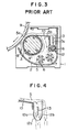
- an improved apparatus as shown in Fig. 3 has been proposed in which an auxiliary magnet roll 16 for developer discharging purpose is provided so that a constant amount of the developer 5c can be forcedly discharged from the outlet of the detector container 12.
- the proposed detecting apparatus has also been defective in that it is difficult to ensure a uniform flow of the developer 5c along the both sides of the detecting element 13, and, also, the apparatus becomes complex and expensive.
- a toner concentration detecting apparatus for use in a developing apparatus comprising a developer container containing a developer including a carrier and a toner, means for transporting the developer contained in the developer container toward and onto the surface of a recording medium having an electrostatic latent image thereon, means for guiding a portion of the developer toward and into a detector container, and means for measuring the mixture ratio of the carrier and the toner in the developer introduced into the detector container, wherein the inner surfaces of opposing side walls of the detector container are so configured that they are formed of curved surfaces of large radii of curvature having their centers on the same side of the detector container and the passage defined between the side wall surfaces is gradually narrowed toward the outlet of the detector container, and a toner concentration detecting element is disposed along substantially the flowing direction of the developer flowing downward in the detector container, whereby to minimize the flow resistance of the detector container and improve the fluidity of the developer.
- the inventors have made researches and studies on an improved form of the detector container 12 as shown in Fi g. 4.
- the corners are eliminated, and side walls 12a and 12b restricting the amount of outflow of the developer are formed by curved surfaces of large radii of curvature gradually narrowing the passage, thereby reducing the resistance against flow of the developer.
- the results of an experiment conducted on the improved detector container 12 shown in Fig. 4 have proved that the performance of the improved detector container 12 is not conspicuously improved over that of the prior art detector container 12 shown in Fig. 1.
- curved surfaces of large radii of curvature having their centers on the same side of the detector container 12 and upper planar surfaces contiguous to those curved surfaces constitute the inner surfaces of the two side walls 12a and 12b when the section is taken at right angles with respect to the flat detecting element 13.
- the passage portions of the developer 5 on the both sides of the detecting element 13 and the joined passage downstream of the detecting element 13 are gradually narrowed toward the outlet of the detector container 12 so that the developer 5 flows downward in substantially the same direction in the detector container 12.
- the flat detecting element 13 is disposed at the center of the passage in a relation inclined at an angle 6 2 with respect to the perpendicular so that the resistance against flow can be minimized.
- the resistance of the inner wall surfaces of the detector container 12 against flow can be minimized and, also, the increase in the flow resistance due to the gradually reduced sectional area of the passage can be minimized.
- the reduction of the fluid driving force in the flowing direction due to collision of the developer portions flowing downward along the both sides of the detecting element 13 can also be suppressed to a minimum. Consequently, it has been experimentally confirmed that the developer shows a very satisfactorily fluidity. It has also been confirmed that the larger the inclination e 1 of the inner curved surface of the side wall 12b with respect to the horizontal, the fluidity is better, and the upper limit of the inclination 8 1 is about 30°.
- Fig. 7 shows one form of the developing apparatus incorporating an embodiment of the toner concentration detecting apparatus of the present invention.
- the developer 5 is attracted toward and onto the peripheral surface of the non-magnetic rotary sleeve 4, and the attracted developer 5 rotating with the non-magnetic sleeve 4 is restricted in thickness by the doctor blade 8 to form a developer brush 5a to be transported toward and onto the surface of the photosensitive drum 9.
- the transported developer brush 5a makes developing engagement at its peripheral surface with the surface of the photosensitive drum 9 having an electrostatic latent image thereon, thereby developing the latent image with the toner.
- the magnetic brush 5a When, thereafter, the magnetic brush 5a is brought to the position opposite to the scraper 10, the developer brush 5a is scraped off from the surface of the non-magnetic sleeve 4 by the scraper 10, and the greater part 5b of the developer 5 falls onto the agitators 6 and 7 for reuse.
- a portion 5c of the scraped developer 5 is guided toward and into the detector container 12 which is constructed as described with reference to Fig. 5 or 6.
- the detector container 12 contains therein the detecting element 13 provided by shaping a coil conductor into a flat rectangular form with a resin.
- the developer 5c introduced into the detector container 12 flows downward along the both sides of the detecting element 13 to be discharged to the exterior of the container 12 for reuse.
- the toner concentration of the developer 5 can be detected on the basis of the inductance value of the coil of the detecting element 13 since the inductance value of the coil of the detecting element 13 depends upon the permeability of the developer 5.
- Fig. 8 shows another form of the developing apparatus incorporating another embodiment of the toner concentration detecting apparatus of the present invention.
- the detector container 12 is disposed in such a relation that the outlet thereof is situated adjacent to the non-magnetic rotary sleeve 4 disposed around the magnet roll 3 in concentric relation therewith.
- the magnet roll 3 is magnetized to have the magnetic poles S1, S 2 and N 2 for developer transporting purpose in addition to the main magnetic pole N l for developing purpose.
- the magnet roll 3 is further provided, at a portion corresponding to the neighborhood of the outlet of the detector container 12, with an auxiliary magnetic pole S 3 of the same polarity as the magnetic pole S 1 disposed adjacent to the inlet of the detector container 12.
- the detecting element 13 employed in the aforementioned embodiments of the present invention is of the permeability sensitive type, it is apparent that it may be replaced by, for example, the type sensitive to the relative quantity of magnetic flux, the type sensitive to the relative flux density or the type sensitive to the conductivity (the electrical resistance) of the developer.
- the magnetic carrier in the developer may be replaced by a non-magnetic carrier.
- the detecting element 13 is preferably of the type sensitive to the conductivity of the developer.
Landscapes
- Physics & Mathematics (AREA)
- General Physics & Mathematics (AREA)
- Chemical & Material Sciences (AREA)
- Dispersion Chemistry (AREA)
- Health & Medical Sciences (AREA)
- Life Sciences & Earth Sciences (AREA)
- Analytical Chemistry (AREA)
- Biochemistry (AREA)
- General Health & Medical Sciences (AREA)
- Immunology (AREA)
- Pathology (AREA)
- Dry Development In Electrophotography (AREA)
- Investigating Or Analyzing Materials By The Use Of Magnetic Means (AREA)
Applications Claiming Priority (2)
| Application Number | Priority Date | Filing Date | Title |
|---|---|---|---|
| JP58146413A JPS6039672A (ja) | 1983-08-12 | 1983-08-12 | トナ−濃度検出装置 |
| JP146413/83 | 1983-08-12 |
Publications (2)
| Publication Number | Publication Date |
|---|---|
| EP0137141A1 true EP0137141A1 (fr) | 1985-04-17 |
| EP0137141B1 EP0137141B1 (fr) | 1988-10-05 |
Family
ID=15407129
Family Applications (1)
| Application Number | Title | Priority Date | Filing Date |
|---|---|---|---|
| EP84108110A Expired EP0137141B1 (fr) | 1983-08-12 | 1984-07-11 | Appareil de détection de la concentration du toner |
Country Status (5)
| Country | Link |
|---|---|
| US (1) | US4583491A (fr) |
| EP (1) | EP0137141B1 (fr) |
| JP (1) | JPS6039672A (fr) |
| KR (1) | KR910004220B1 (fr) |
| DE (1) | DE3474480D1 (fr) |
Families Citing this family (3)
| Publication number | Priority date | Publication date | Assignee | Title |
|---|---|---|---|---|
| US4999676A (en) * | 1989-03-27 | 1991-03-12 | Casio Computer Co., Ltd. | Image forming apparatus having common signal lines |
| CA2487405A1 (fr) * | 2002-07-26 | 2004-02-05 | Emphasys Medical, Inc. | Dispositifs de regulation de debit bronchique a joint membranaire |
| JP6685773B2 (ja) | 2016-03-02 | 2020-04-22 | キヤノン株式会社 | 現像装置 |
Citations (5)
| Publication number | Priority date | Publication date | Assignee | Title |
|---|---|---|---|---|
| US3956108A (en) * | 1973-07-30 | 1976-05-11 | Xerox Corporation | Anti-plugging device for automatic developability control systems |
| US3999687A (en) * | 1974-07-17 | 1976-12-28 | Savin Business Machines Corporation | Toner concentration detector |
| US4131081A (en) * | 1976-04-14 | 1978-12-26 | Hitachi, Ltd. | Toner concentration detecting apparatus |
| US4240375A (en) * | 1977-04-13 | 1980-12-23 | Hitachi, Ltd. | Apparatus for detecting concentration of toner in developing powder |
| EP0029710A1 (fr) * | 1979-11-24 | 1981-06-03 | Hitachi, Ltd. | Appareil pour la détection de la concentration d'agent de développement |
-
1983
- 1983-08-12 JP JP58146413A patent/JPS6039672A/ja active Granted
-
1984
- 1984-07-10 KR KR1019840004000A patent/KR910004220B1/ko not_active Expired
- 1984-07-11 DE DE8484108110T patent/DE3474480D1/de not_active Expired
- 1984-07-11 EP EP84108110A patent/EP0137141B1/fr not_active Expired
- 1984-07-27 US US06/635,151 patent/US4583491A/en not_active Expired - Fee Related
Patent Citations (5)
| Publication number | Priority date | Publication date | Assignee | Title |
|---|---|---|---|---|
| US3956108A (en) * | 1973-07-30 | 1976-05-11 | Xerox Corporation | Anti-plugging device for automatic developability control systems |
| US3999687A (en) * | 1974-07-17 | 1976-12-28 | Savin Business Machines Corporation | Toner concentration detector |
| US4131081A (en) * | 1976-04-14 | 1978-12-26 | Hitachi, Ltd. | Toner concentration detecting apparatus |
| US4240375A (en) * | 1977-04-13 | 1980-12-23 | Hitachi, Ltd. | Apparatus for detecting concentration of toner in developing powder |
| EP0029710A1 (fr) * | 1979-11-24 | 1981-06-03 | Hitachi, Ltd. | Appareil pour la détection de la concentration d'agent de développement |
Also Published As
| Publication number | Publication date |
|---|---|
| EP0137141B1 (fr) | 1988-10-05 |
| DE3474480D1 (en) | 1988-11-10 |
| KR850002318A (ko) | 1985-05-10 |
| JPS6039672A (ja) | 1985-03-01 |
| JPH0242224B2 (fr) | 1990-09-21 |
| US4583491A (en) | 1986-04-22 |
| KR910004220B1 (ko) | 1991-06-24 |
Similar Documents
| Publication | Publication Date | Title |
|---|---|---|
| US4324483A (en) | Magnetic brush development apparatus | |
| EP2842000B1 (fr) | Dispositif de développement | |
| US4638760A (en) | Developing apparatus | |
| US4993829A (en) | Developing apparatus for an image forming apparatus | |
| EP0219233A2 (fr) | Procédé et appareil pour le développement | |
| US7050745B2 (en) | Two-component developer unit of electrophotographic image forming apparatus having lifting guide portion | |
| US5239343A (en) | Developing apparatus with regulating member having magnetic and non-magnetic members | |
| US4583491A (en) | Toner concentration detecting apparatus | |
| CN100424591C (zh) | 显影装置和图像形成装置 | |
| EP0964313B1 (fr) | Dispositif de développement et appareil de formation d'images | |
| JP2003295617A (ja) | 現像装置および静電記録装置 | |
| JPH07325486A (ja) | 静電写真プリンタに使用される現像ユニット | |
| JPH1144997A (ja) | 現像装置 | |
| JPS648821B2 (fr) | ||
| US4428661A (en) | Magnetic brush type developing device | |
| JP2819550B2 (ja) | 現像装置 | |
| JPH02256082A (ja) | 現像装置 | |
| JPS6018062B2 (ja) | トナ−コントロ−ル装置 | |
| JP5509157B2 (ja) | 現像装置及びそれを備えた画像形成装置 | |
| JPS58179882A (ja) | 磁性トナ−による静電潜像の現像装置 | |
| JPS6028357B2 (ja) | 現像剤のトナ−濃度検出装置 | |
| JPH02135366A (ja) | 二成分系現像剤および該現像剤を用いた現像方法 | |
| JPS6034110B2 (ja) | 磁気ブラシ現像装置 | |
| JPS6337381B2 (fr) | ||
| JPS60153067A (ja) | 磁気ブラシ現像ロ−ラ |
Legal Events
| Date | Code | Title | Description |
|---|---|---|---|
| PUAI | Public reference made under article 153(3) epc to a published international application that has entered the european phase |
Free format text: ORIGINAL CODE: 0009012 |
|
| 17P | Request for examination filed |
Effective date: 19840711 |
|
| AK | Designated contracting states |
Designated state(s): DE FR IT |
|
| 17Q | First examination report despatched |
Effective date: 19870219 |
|
| GRAA | (expected) grant |
Free format text: ORIGINAL CODE: 0009210 |
|
| AK | Designated contracting states |
Kind code of ref document: B1 Designated state(s): DE FR IT |
|
| REF | Corresponds to: |
Ref document number: 3474480 Country of ref document: DE Date of ref document: 19881110 |
|
| ET | Fr: translation filed | ||
| ITF | It: translation for a ep patent filed | ||
| PLBE | No opposition filed within time limit |
Free format text: ORIGINAL CODE: 0009261 |
|
| STAA | Information on the status of an ep patent application or granted ep patent |
Free format text: STATUS: NO OPPOSITION FILED WITHIN TIME LIMIT |
|
| 26N | No opposition filed | ||
| ITTA | It: last paid annual fee | ||
| PGFP | Annual fee paid to national office [announced via postgrant information from national office to epo] |
Ref country code: FR Payment date: 19920529 Year of fee payment: 9 |
|
| PGFP | Annual fee paid to national office [announced via postgrant information from national office to epo] |
Ref country code: DE Payment date: 19920825 Year of fee payment: 9 |
|
| PG25 | Lapsed in a contracting state [announced via postgrant information from national office to epo] |
Ref country code: FR Effective date: 19940331 |
|
| PG25 | Lapsed in a contracting state [announced via postgrant information from national office to epo] |
Ref country code: DE Effective date: 19940401 |
|
| REG | Reference to a national code |
Ref country code: FR Ref legal event code: ST |