EP0137272B1 - Dispositif de focalisation automatique - Google Patents
Dispositif de focalisation automatique Download PDFInfo
- Publication number
- EP0137272B1 EP0137272B1 EP19840110194 EP84110194A EP0137272B1 EP 0137272 B1 EP0137272 B1 EP 0137272B1 EP 19840110194 EP19840110194 EP 19840110194 EP 84110194 A EP84110194 A EP 84110194A EP 0137272 B1 EP0137272 B1 EP 0137272B1
- Authority
- EP
- European Patent Office
- Prior art keywords
- light
- light receiving
- central
- output signal
- automatic focusing
- Prior art date
- Legal status (The legal status is an assumption and is not a legal conclusion. Google has not performed a legal analysis and makes no representation as to the accuracy of the status listed.)
- Expired
Links
Images


Classifications
-
- G—PHYSICS
- G11—INFORMATION STORAGE
- G11B—INFORMATION STORAGE BASED ON RELATIVE MOVEMENT BETWEEN RECORD CARRIER AND TRANSDUCER
- G11B7/00—Recording or reproducing by optical means, e.g. recording using a thermal beam of optical radiation by modifying optical properties or the physical structure, reproducing using an optical beam at lower power by sensing optical properties; Record carriers therefor
- G11B7/12—Heads, e.g. forming of the optical beam spot or modulation of the optical beam
- G11B7/13—Optical detectors therefor
-
- G—PHYSICS
- G11—INFORMATION STORAGE
- G11B—INFORMATION STORAGE BASED ON RELATIVE MOVEMENT BETWEEN RECORD CARRIER AND TRANSDUCER
- G11B7/00—Recording or reproducing by optical means, e.g. recording using a thermal beam of optical radiation by modifying optical properties or the physical structure, reproducing using an optical beam at lower power by sensing optical properties; Record carriers therefor
- G11B7/08—Disposition or mounting of heads or light sources relatively to record carriers
- G11B7/09—Disposition or mounting of heads or light sources relatively to record carriers with provision for moving the light beam or focus plane for the purpose of maintaining alignment of the light beam relative to the record carrier during transducing operation, e.g. to compensate for surface irregularities of the latter or for track following
- G11B7/0908—Disposition or mounting of heads or light sources relatively to record carriers with provision for moving the light beam or focus plane for the purpose of maintaining alignment of the light beam relative to the record carrier during transducing operation, e.g. to compensate for surface irregularities of the latter or for track following for focusing only
- G11B7/0909—Disposition or mounting of heads or light sources relatively to record carriers with provision for moving the light beam or focus plane for the purpose of maintaining alignment of the light beam relative to the record carrier during transducing operation, e.g. to compensate for surface irregularities of the latter or for track following for focusing only by astigmatic methods
-
- G—PHYSICS
- G11—INFORMATION STORAGE
- G11B—INFORMATION STORAGE BASED ON RELATIVE MOVEMENT BETWEEN RECORD CARRIER AND TRANSDUCER
- G11B7/00—Recording or reproducing by optical means, e.g. recording using a thermal beam of optical radiation by modifying optical properties or the physical structure, reproducing using an optical beam at lower power by sensing optical properties; Record carriers therefor
- G11B7/08—Disposition or mounting of heads or light sources relatively to record carriers
- G11B7/09—Disposition or mounting of heads or light sources relatively to record carriers with provision for moving the light beam or focus plane for the purpose of maintaining alignment of the light beam relative to the record carrier during transducing operation, e.g. to compensate for surface irregularities of the latter or for track following
- G11B7/094—Methods and circuits for servo offset compensation
Definitions
- the invention relates to an automatic focusing device comprising an objective lens for focusing a light beam emitted by a light source on a track of an information recording medium; a beam splitter for separating a reflected light beam reflected by the information recording medium at a focal spot thereon and through the objective lens from the light beam emitted by the light source; an astigmatic optical system including an optical element capable of causing astigmatic aberration of the separated reflected light beam; a light detector having a central light receiving section for information reading and a side light receiving surface adjacent to the central section and divided into a plurality of light receiving sections which are arranged symmetrically with respect to a first axis (X) extending in parallel to the axial direction of the optical element and to a second axis (Y) extending perpendicularly to the first axis (X) and adapted to receive the reflected beam transmitted through the optical element and to give a light reception output signal corresponding to the shape of the spot of the reflected light beam formed on the light receiving surface; a
- Such an automatic focusing device is known from JP-A-58 88 842 (patent abstracts of Japan, volume 7, number 188, (P-217), 17 August 1983).
- optical disk head Astigmatic optical system for information detection and for focal position detection.
- Fig. 1 is a schematic light passage diagram of a known automatic focusing device of an optical disk head employing an astigmatic optical system
- Fig. 2 is a perspective view of part of the light passage of Fig. 1
- Fig. 3 is a circuit diagram of a servo mechanism including a light detector and the following circuits. Referring to Figs.
- a light source 1 such as a semiconductor laser
- a light beam 2 emitted by the light source 1 an objective lens 3
- an optical disk 4 serving as an information recording medium, storing digital audio signals or video signals in tracks and placed in the vicinity of the focal point of the objective lens
- a reflected light beam 5 reflected from a focal spot on the disk 4 and transmitted through the objective lens 3
- a beam splitter 6 for separating the radiated light beam 2 and the reflected light beam 5
- a cylindrical lens 7 serving as an optical element for causing the astigmatic aberration of the reflected light beam 5 and having a longitudinal axis x extending perpendicularly to the surface of the sheet and an axis y extending perpendicularly to the axis x.
- a light detector 8 is divided into four sections 8a, 8b, 8c and 8d by division lines extending at an angle of 45° with respect to the x-direction and y-direction respectively, a reflection beam spot 9 formed in the light detector 8 by the reflected light beam 5, a focal point detecting circuit 10 consisting of adders 11 and 12 and a differential amplifier 13, an information detecting circuit 14 formed of an adder, a focus actuator 15 for moving the objective lens along the optical axis, a lens driving circuit 16 which energizes the focus actuator 15 to drive the objective lens, and a connection 17 to an information reproducing circuit, not shown.
- a laser beam 2 emitted by the light source 1 is focused by the objective lens 3 and forms a light spot on a track of the disk 4.
- the disk 4 has an irregular surface formed of minute pits. Information is formed in the form of those pits. As the disk 4 is rotated, the laser beam radiated on the surface of the disk 4 is modulated by the pits and is reflected.
- the reflected light beam 5 is separated from the laser beam 2 by the beam splitter 6 and is converted into an astigmatic beam which is converged in a single direction, by the cylindrical lens 7.
- the cylindrical lens 7 does not have the function of lens in the x-direction, therefore, the reflected beam is focused on a point P by the objective lens 3, while in the y-direction, the reflected beam is focused on a point Q by the focusing function of the cylindrical lens 7.
- the form of light distribution of the astigmatic reflected beam at the point Q, at the point P and at an intermediate point V between the points P and Q is an ellipse elongated in the x-direction, an ellipse elongated in the y-direction and an ellipse elongated either in the x-direction or in the y-direction or a circle, respectively.
- the four-section light detector 8 is located at a position where the form of the light distribution of the astigmatic reflected beam is a circle, namely, the intermediate position V, when the disk 4 is positioned at a position corresponding to the focal point of the objective lens 3 (this position will be referred to as "focused position” hereinafter). Accordingly, the form of the spot 9 of the reflected beam on the light detector 8 is a circle when the disk 4 is at the focused position, an ellipse elongated in the x-direction when the disk 4 is at a position displaced toward the objective lens 3 from the focused position and an ellipse elongated in the y-direction when the disk 4 is displaced from the focused position away from the objective lens 3.
- the light receiving sections 8a, 8b, 8c and 8d receive light equally.
- the spot 9 of the reflected light is an ellipse elongated in the x-direction
- the light receiving sections 8a and 8c receives more light than the rest of the light receiving sections.
- the spot 9 of the reflected beam is an ellipse elongated in the y-direction
- the light receiving sections 8b and 8d receives more light than the rest of the light receiving sections.
- the output signal of the differential amplifier 13, i.e., the output signal E f of the focal position detecting circuit 10, corresponding to the difference between the output signal given by the adder 11 corresponding to the sum of the light reception outputs of the light receiving sections 8a and 8c and the output signal given by the adder 12 corresponding to the sum of the light reception outputs of the light receiving sections 8b and 8d is zero when the disk 4 is at the focused position, a positive value when the objective lens 3 is moved toward the optical disk 4 from the focused position and the spot 9 of the reflected beam is an ellipse elongated in the x-direction, and a negative value when the objective lens 3 is moved from the focused position away from the optical disk 4 and the spot 9 is an ellipse elongated in the y-direction.
- the magnitude of the output signal of the focal position detecting circuit is approximately proportional to the deviation of the objective lens 3 from the focused position. Accordingly, the objective lens 3 is focused automatically by energizing the focus actuator 15 through the control of the lens driving circuit 16 by the output signal E f of the focal position detecting circuit 10 to move the objective lense 3 along the optical axis.
- the information read out from the optical disk 5 and carried by the reflected beam 5 is taken out by an information detecting circuit 14 which receives the sum of the light reception output signals of the light receiving sections.
- the conventional automatic focusing device as described hereinbefore has the following problems in its practical use.
- Fig. 4A showing the detail of the constitution of the four-section light detectors 8 of Fig. 3, there is a blind zone 18 of a finite width between the light receiving sections 8a, 8b, 8c and 8d to separate those light receiving sections from each other. If the width of this blind zone 18 is too narrow, cross talk between those light receiving sections increases and the output signal corresponding to the calculated difference is reduced adversely.
- the diameter of the spot 9 when the objective lens is at the focused position is about 100 ⁇ m and the lower limit of the width of the blind zone is approximately 10 to 15 ⁇ m.
- the energy of a portion of the flux of the incident light on the light detector 8 that falls on the blind zone 18 does not contribute at all neither to the output of the focal position detecting circuit 10 nor to the output of the information detecting circuit 14.
- the reflected beam 5 is a Gaussian beam as shown in Fig. 4B and the center O of the reflected beam 5, where the flux density of the reflected beam 5 is the highest, coincides with the central portion of the light detector 8 where the blind zone is extending, the focused state detecting sensitivity is relatively low as compared with the sensitivity of detection in an ideal condition where the width of the blind zone is zero and cross talk does not occur. Still further, the loss of the incident energy due to the presence of the blind zone causes the reduction in the output of the information detecting circuit 14, which entails the deterioration of the SN ratio.
- the output E f of the differential amplifier 13 is zero when the objective lens is focused, which, however, does not mean that the intensity of the incident light on the light detector 8 is zero.
- the output E f becomes zero merely because the sum of the incident light fluxes on the light receiving sections 8a and 8c and the sum of the incident light fluxes on the light receiving sections 8b and 8d are balanced. If the distribution of the incident light flux on the light detector 8 is changed by some cause, the balance is destroyed and the differential amplifier 13 gives an output signal as if the objective lens has become out of focus, despite the objective lens being in focus.
- One of the causes of such destruction of the balance is the variation of the light source 1 in the light emission distribution.
- the variation of the excitation current or the secular deterioration of the semiconductor laser causes the variation of the light emission distribution.
- the flux distribution forms a conical distribution curve having a single peak at the center where the flux density is the highest and, since the center of the four-section light detector coincides with the center of the reflected beam, even a slight variation in the flux distribution affects the balance greatly.
- the pregroove (guide track) of an add-on disk (a disk capable of recording) and refractive light from the recording pit are other factors affecting the balance.
- the distribution pattern of the diffractive light is not necessarily symmetrical with respect to the optical axis and is subject to the extent of the deviation of the track and whether or not any signal is recorded in the pregroove. Consequently, the form of the spot of the reflected beam which is to be circular when the objective lens is focused is deformed and the offset of a tracking point occurs.
- JP-A-58 88 842 it is known to have a central light receiving section for information reading and a side light receiving surface adjacent to the central section and divided into a plurality of light receiving sections.
- the central light receiving section uses a special photo detector having a high response and high frequency characteristics as compared with the other areas.
- EP-A-75 676 it is known to use special detection areas for tracking error detection, but it is not used for focusing error detection.
- US-A-42 96 316 shows an optical focusing device having one central narrow area and two adjacent larger areas. Such a device, however, has the disadvantage of a non-linear sensing characteristic around the two focusing point, so that it is difficult to provide an appropriate control system.
- an optical head comprising two photosensitive regions and an intermediate, non-photosensitive region there between. This arrangement can also be defined with four photosensitive areas.
- Such an optical head has the disadvantage that for reading optical information, either a different head has to be used, or the sensitivity is greatly reduced if the focused spot only reaches the edges of the two or four distant photosensitive areas.
- one embodiment of the present invention is characterized in that the central light receiving section has a width in the second axis (Y) which is equal or slightly smaller than the diameter of the light spot when focused, and widens up to both sides in the direction of the first axis (X).
- Figure 5 is a schematic view showing the constitution and the circuit of a light detector employed in the first embodiment of an automatic focusing device according to the present invention.
- Other parts and the constitution of the automatic focusing device are the same as those of the automatic focusing device of Figs. 1 to 3.
- Like reference characters designate like or corresponding parts through Figs. 3 and 5.
- a focal position detecting circuit 10 consists only of an adder 12 and a differential amplifier 13.
- a light detector 19 is divided, by division lines 21 and 22 which are bent in the central portion of the light detector 19, into three light receiving sections, namely, a central light receiving section 19a, 19c with a constricted central portion and side light receiving sections 19b and 19d which are formed opposite to each other on the opposite sides of the central light receiving section 19a, 19c.
- the shape of the central light receiving section 19a is axially symmetric with respect to both an axis extending in an x-direction and an axis extending in a y-direction which intersect perpendicularly each other at the center of the light detector 19.
- the form of each of the side light receiving sections 19b and 19d is axially symmetric with respect to the axis extending in the y-direction.
- the focal position detecting function and the automatic focusing function of the automatic focusing device employing this light detector 19 are the same as those of the conventional automatic focusing device as shown in Figs. 1 to 3.
- the automatic focusing device of the present invention has advantages over the conventional automatic focusing device.
- the light receiving sections 8a and 8c are interconnected by the external adder 11
- the light receiving section corresponding to the light receiving sections 8a and 8c are interconnected internally by a connecting part 20 to form a single light receiving section 19a, and hence the adder 11 is unnecessary.
- the connecting part 20 is provided instead of division lines in the central portion of the light detector, where the flux density of the spot of the reflected beam is the highest and the division line affects greatly to the light energy loss, to receive the light flux of the central portion of the light spot efficiently. Therefore, the focus deviation detecting sensitivity is increased. Still further, the effective use of the light flux in the central portion of the light detector enables an information detecting circuit 14 to give a reproduction signal of increased amplitude level, which contributes to the improvement of the SN ratio.
- the present invention enables, in addition to those improvements, the reduction of components, such as the adder 11, and the improvement of reliability without deteriorating the performance of the automatic focusing device, and thereby the reduction of the manufacturing cost. Furthermore, since the edge angle of the opposed apexes of the side light receiving sections 19b and 19c can be increased, the deterioration of the dielectric strength due to the concentration of electric field on the apexes is prevented.
- Fig. 6 shows the constitution and the circuit of a light detector employed in the second embodiment of the present invention, in which the like parts corresponding to those shown in Figs. 1 and 3 are designated by like reference characters and detailed description thereof will be omitted.
- a light detector 23 has a central light receiving section 23a and an outer light receiving section 23b.
- the shape of the central light receiving section 23a corresponds to the union of the light receiving sections 8a and 8c of Fig. 3. That is, the central light receiving section 23a has a construction corresponding to the connection of the light receiving sections 8a and 8c by a central constricted part 24.
- the outer light receiving section 23b has a construction corresponding to the connection of the light receiving sections 8b and 8d of Fig. 3 by connecting parts 25, i.e., shaded parts in Fig. 6, and surrounding the constricted part 24.
- the two-section light detector 23 is approximately symmetric with respect to an axis extending in the x-direction and is disposed so that the central light receiving section 23a is symmetric with respect to two perpendicular axes extending in the x-direction and the y-direction respectively and the central portion thereof coincides with the central portion of the spot of the laser beam. Accordingly, the shape of the spot of the laser beam, i.e., the spot 9 of the reflected light, changes from a shape 9 indicated by solid line to a shape 9a or 9b indicated by broken lines as the optical disk is displaced from the focused position.
- the output signals given by the light receiving sections 23a and 23b corresponds to the output signals given by the adders 11 and 12 of Fig. 3. Therefore, the light receiving sections 23a and 23b are connected directly to a differential amplifier 26 and the differential amplifier 26 gives an output signal corresponding to the degree of the deviation of the objective lens from the focused position. Automatic focusing is attained by moving the objective lens 3 toward or away from the optical disk by a lens driving circuit 16 on the basis of the output signal given by the differential amplifier 26.
- the two-section light detector 23 of the second embodiment has the central constricted part 24, namely, a part having no division line, and hence the two-section light detector 23 provides the same functional effects as those of the light detector 19 of the first embodiment.
- the light detector 23 has only two lead wires, whereas the light detector 8 of Fig. 3 has four lead wires and the adders 11 and 12 are omitted, and thereby the number of the components is reduced and the reliability is improved without deteriorating the performance of the automatic focusing device.
- the light spot needs to be moved radially according to the eccentric rotation of the optical disk 4 in order to make the light spot keep track of a single information track all the time.
- Such a correction of the position of the light spot is attained by translating the objective lens 3 radially.
- Such a radial movement of the light spot according to the eccentric rotation of the optical disk is designated as "tracking".
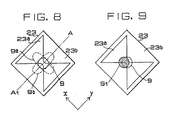
- the laser beam spot moves on the detector 23 in the y-direction from a position indicated by a circle 9 to a position indicated by a circle 91. Consequently, the output of the light receiving section 23a and the output of the light receiving section 23b are unbalanced despite the shape of the laser beam spot being circular, and thereby the objective lens 3 is shifted, which brings about a reverse correcting effect resulting in the incorrect adjustment of the objective lens.
- a cylindrical lens 7 is disposed with its axis extending approximately at an angle of 45° to the information track of the optical disk and the light detector 23 is disposed, as shown in Fig. 8, with an axis of symmetry A-A1 extended approximately at an angle of 45° to a direction along the information track.
- the positional relation between the laser beam spot and the light detector 23 is shown in Fig. 8.
- Fig. 9 shows the positions of the laser beam spot on the light detector before and after tracking, when the light detector is disposed as shown in Fig. 8.
- An example of the application of the above-mentioned principle of performance to the four-section light detector 8 shown in Fig. 3 is disclosed in Japanese Patent Publication No. 53-37722.
- the division lines 21, 22, 27 and 28 are bent approximately at a right angle denoted as ⁇ , however, the bending angles of those division lines are not necessarily be a right angle. Since the connecting parts 20 and 24 are formed on the light detectors 19 and 23 respectively, it is possible that the output of the light receiving section 19a and the output of the light receiving sections 19b and 19d, and the output of the light receiving section 23a and the output of the light receiving section 23b are not balanced. In such a case, it is possible to compensate the unbalance by designing the light detector so that the central bending angle ⁇ is an angle greater than 90°.
- the light receiving surface of a light detector except the central portion thereof is divided into a plurality of light receiving sections which are arranged symmetrically with respect to a first axis extending in parallel to the axial direction of an optical element and to a second axis extending perpendicularly to the first axis, therefore, the loss of received light energy attributable to the presence of division lines forming a blind zone is reduced, and thereby an automatic focusing device of reduced zero-drifting and high stability is provided.
- the present invention enhances the sensitivity of detecting the change of focus, improves the SN ratio of the information detecting circuit and the reliability, reduces the number of components and the manufacturing cost and prevents the deterioration of the dielectric strength of the light receiving sections.
Landscapes
- Physics & Mathematics (AREA)
- Optics & Photonics (AREA)
- Optical Recording Or Reproduction (AREA)
- Automatic Focus Adjustment (AREA)
Claims (9)
- Dispositif de focalisation automatique comprenant :
un objectif (3) pour focaliser un faisceau lumineux (2) émis par une source de lumière (1) sur une piste d'un support d'enregistrement d'informations (4) ;
un diviseur de faisceau (6) pour séparer du faisceau lumineux (2) émis par la source de lumière (1) un faisceau lumineux (5) réfléchi par le support d'enregistrement d'informations (4) au niveau d'un point focal sur celui-ci et à travers l'objectif (3) ;
un système optique astigmate comprenant un élément optique (7) apte à engendrer une aberration astigmate du faisceau lumineux réfléchi séparé (5) ;
un détecteur de lumière (19, 23) comportant une section centrale de réception de lumière (19a, 19c; 23a) pour une lecture d'informations et une surface latérale de réception de lumière adjacente à la section centrale et divisée en une pluralité de sections de réception de lumière (19b, 19d; 23b) qui sont disposées symétriquement par rapport à un premier axe (X) s'étendant parallèlement à la direction axiale de l'élément optique (7) et à un second axe (Y) s'étendant perpendiculairement au premier axe (X) et apte à recevoir le faisceau réfléchi (5) transmis à travers l'élément optique (7) et à fournir un signal de sortie de réception de lumière correspondant à la forme du point (9) du faisceau lumineux réfléchi (5) formé sur la surface de réception de lumière ;
un circuit de détection de position focale (10) apte à fournir un signal de sortie correspondant au déplacement de l'objectif (3) à partir de la position focalisée, sur la base du signal de sortie fourni par le détecteur de lumière (19, 23) ; et un circuit d'entraînement d'objectif (16) qui entraîne l'objectif (3) le long de l'axe optique sur la base du signal de sortie fourni par le circuit de détection de position focale (10),
caractérisé en ce que la section centrale de réception de lumière (19a, 19c; 23a) présente une largeur dans le second axe (Y) qui est égale ou légèrement inférieure amètre du point lumineux lorsqu'il est focalisé, et va en s'élargissant vers les deux côtés dans la direction du premier axe (X). - Dispositif de focalisation automatique selon la revendication 1, dans lequel ledit détecteur de lumière est un détecteur de lumière (19) à trois sections comportant une section centrale de réception de lumière (19a, 19c) présentant une forme qui est approximativement symétrique par rapport aux premier (X) et second (Y) axes et comporte une partie centrale rétrécie (20), et des sections latérales de réception de lumière (19b, 19d) formées approximativement symétriquement par rapport aux premier (X) et second (Y) axes et disposées de façon que leurs sommets soient en regard l'un de l'autre.
- Dispositif de focalisation automatique selon la revendication 2, dans lequel ledit circuit de détection de position focale (10) comporte un additionneur (12) pour additionner les signaux de sortie de réception de lumière des sections latérales de réception de lumière (19b, 19d) dudit détecteur de lumière (19) ; et un amplificateur différentiel (13) apte à fournir un signal de sortie correspondant à la différence entre le signal de sortie de réception de lumière de la section centrale de réception de lumière (19a, 19c) et le signal de sortie fourni par l'additionneur (12).
- Dispositif de focalisation automatique selon la revendication 2, caractérisé par un additionneur (12) pour additionner les signaux de sortie de réception de lumière des sections latérales de réception de lumière (19b, 19d) dudit détecteur de lumière (19) et un circuit de détection d'informations (14) pour additionner le signal de sortie de réception de lumière de la section centrale de réception de lumière (19a, 19c) et le signal de sortie dudit additionneur (12).
- Dispositif de focalisation automatique selon la revendication 1, dans lequel ledit détecteur de lumière est un détecteur de lumière (23) à deux sections, comportant une section centrale de réception de lumière (23a) présentant une forme qui est approximativement symétrique par rapport aux premier (X) et second (Y) axes et comporte une partie centrale rétrécie (24) et une section externe de réception de lumière (23b) entourant la section centrale de réception de lumière (23a) ;
- Dispositif de focalisation automatique selon la revendication 5, dans lequel ledit circuit de détection de position focale est doté d'un amplificateur différentiel (26) qui fournit un signal de sortie différentiel correspondant à la différence entre le signal de sortie de réception de lumière fourni par la section centrale de réception de lumière (23a) et le signal de sortie de réception de lumière fourni par la section externe de réception de lumière (23b).
- Dispositif de focalisation automatique selon la revendication 2 ou 5, dans lequel des angles de courbure centrale (ϑ) de lignes de division (21, 22; 27, 28) entre les sections de réception de lumière sont des angles droits.
- Dispositif de focalisation automatique selon la revendication 2 ou 5, dans lequel des angles de courbure centrale (ϑ) de lignes de division (21, 22 ; 27, 28) entre les sections de réception de lumière sont des angles obtus.
- Dispotif de focalisation automatique selon la revendication 1, dans lequel ledit élément optique (7) est disposé de façon que son axe s'étende approximativement suivant un angle de 45° par rapport à la direction de la piste d'informations.
Applications Claiming Priority (6)
| Application Number | Priority Date | Filing Date | Title |
|---|---|---|---|
| JP58162823A JPS6055521A (ja) | 1983-09-05 | 1983-09-05 | 光デイスクヘツドの自動焦点調節装置 |
| JP162823/83 | 1983-09-05 | ||
| JP17848683A JPS6070534A (ja) | 1983-09-27 | 1983-09-27 | 自動焦点調節装置 |
| JP178486/83 | 1983-09-27 | ||
| JP191280/83 | 1983-10-13 | ||
| JP58191280A JPS6083229A (ja) | 1983-10-13 | 1983-10-13 | 光デイスクヘツドの自動焦点調節装置 |
Publications (3)
| Publication Number | Publication Date |
|---|---|
| EP0137272A2 EP0137272A2 (fr) | 1985-04-17 |
| EP0137272A3 EP0137272A3 (en) | 1987-08-05 |
| EP0137272B1 true EP0137272B1 (fr) | 1991-06-19 |
Family
ID=27322064
Family Applications (1)
| Application Number | Title | Priority Date | Filing Date |
|---|---|---|---|
| EP19840110194 Expired EP0137272B1 (fr) | 1983-09-05 | 1984-08-28 | Dispositif de focalisation automatique |
Country Status (2)
| Country | Link |
|---|---|
| EP (1) | EP0137272B1 (fr) |
| DE (1) | DE3484723D1 (fr) |
Families Citing this family (9)
| Publication number | Priority date | Publication date | Assignee | Title |
|---|---|---|---|---|
| NL8501665A (nl) * | 1985-06-10 | 1987-01-02 | Philips Nv | Optische aftasteenheid met positie- en standdetektiestelsel voor een elektromagnetisch gelagerd objektief. |
| EP0261545A1 (fr) * | 1986-09-17 | 1988-03-30 | Siemens Aktiengesellschaft | Dispositif détecteur pour déterminer l'erreur de focalisation d'un enregistreur optique de données |
| JPS63225927A (ja) * | 1987-03-13 | 1988-09-20 | Pioneer Electronic Corp | 焦点誤差検出装置 |
| EP0283002B1 (fr) * | 1987-03-17 | 1994-02-16 | Matsushita Electric Industrial Co., Ltd. | Tête optique |
| US4816665A (en) * | 1987-08-06 | 1989-03-28 | Maxtor Corporation | Sensor array for focus detection |
| JPH0648575Y2 (ja) * | 1988-09-13 | 1994-12-12 | パイオニア株式会社 | 光検出器 |
| DE10125469B4 (de) | 2001-05-25 | 2008-01-10 | Leica Microsystems Cms Gmbh | Vorrichtung zur Ermittlung einer Lichtleistung, Mikroskop und Verfahren zur Mikroskopie |
| CN114235868B (zh) * | 2020-09-09 | 2023-06-20 | 中国科学院沈阳科学仪器股份有限公司 | 一种具有自动调焦功能的差分高能电子衍射系统及方法 |
| CN113137934B (zh) * | 2021-04-23 | 2022-10-28 | 中国工程物理研究院流体物理研究所 | 一种单探头射线方程的标定系统及标定方法 |
Family Cites Families (6)
| Publication number | Priority date | Publication date | Assignee | Title |
|---|---|---|---|---|
| NL7600843A (nl) * | 1976-01-28 | 1977-08-01 | Philips Nv | Inrichting voor het uitlezen van een registratie- drager waarop informatie, bijvoorbeeld en/of ge- luidsinformatie, is aangebracht. |
| GB1532345A (en) * | 1976-06-25 | 1978-11-15 | Hitachi Ltd | Information play-back apparatus |
| US4290132A (en) * | 1977-05-11 | 1981-09-15 | Pioneer Electronic Corporation | Focus servo device for use in an optical information read-out device |
| JPS5821334B2 (ja) * | 1978-12-25 | 1983-04-28 | 株式会社東芝 | 自動焦点調節装置 |
| EP0070552B1 (fr) * | 1981-07-20 | 1990-06-27 | Kabushiki Kaisha Toshiba | Tête optique |
| JPS5856236A (ja) * | 1981-09-28 | 1983-04-02 | Hitachi Ltd | 光学的トラック位置検出装置およびそれを用いた光学的記録再生装置 |
-
1984
- 1984-08-28 EP EP19840110194 patent/EP0137272B1/fr not_active Expired
- 1984-08-28 DE DE8484110194T patent/DE3484723D1/de not_active Expired - Lifetime
Also Published As
| Publication number | Publication date |
|---|---|
| DE3484723D1 (de) | 1991-07-25 |
| EP0137272A2 (fr) | 1985-04-17 |
| EP0137272A3 (en) | 1987-08-05 |
Similar Documents
| Publication | Publication Date | Title |
|---|---|---|
| EP0545133B1 (fr) | Dispositif de réproduction optique et dispositif de focalisation pour celui-ci | |
| US5638353A (en) | Optical head device | |
| JP2000021014A (ja) | 収差補正方法及び収差補正装置 | |
| HK46589A (en) | Method and apparatus for tracking an optically readable information track | |
| EP0992987B1 (fr) | Appareil de lecture optique | |
| JP3889104B2 (ja) | 光ピックアップ装置 | |
| EP0137272B1 (fr) | Dispositif de focalisation automatique | |
| JPH0358323A (ja) | 光学式情報読取り装置 | |
| US4625303A (en) | Automatic focusing device | |
| PL182121B1 (pl) | Sposób oraz urzadzenie do selektywnego zapisywania i odtwarzania informacji PL | |
| JP3879897B2 (ja) | 光ピックアップ装置 | |
| US5018127A (en) | Light emitting apparatus having a plurality of light emitting points | |
| US5029261A (en) | Apparatus for detecting position of light beam on object surface by comparing detection beams split near focal point | |
| US4888752A (en) | Focusing and tracking servo system for controlling the projection of an optical beam on an optical disk | |
| US6167017A (en) | Optical head assembly having means for detecting tracking errors based on astigmatisms generated by returning beams | |
| EP1005031A2 (fr) | Lecteur multifaisceaux à réglage convenable de la distance entre la lentille d'objectif et le support d'enregistrement optique d'information | |
| EP0367465B1 (fr) | Dispositifs d'enregistrement optique | |
| JP2731405B2 (ja) | 分離型光ピックアップ装置における光軸ずれ補正方法 | |
| JP2788141B2 (ja) | 光ディスク装置のエラー検出装置 | |
| EP0292107B1 (fr) | Dispositif pour tête optique | |
| KR900008405B1 (ko) | 광학식 헤드 장치 | |
| US7330418B2 (en) | Optical disk with plural signal mark positions in a direction substantially perpendicular to tracks | |
| JP2643287B2 (ja) | 光検出器 | |
| JP2615954B2 (ja) | 光ヘッド装置及びこれを用いた光情報処理装置 | |
| JPS6076038A (ja) | 光学式情報処理装置 |
Legal Events
| Date | Code | Title | Description |
|---|---|---|---|
| PUAI | Public reference made under article 153(3) epc to a published international application that has entered the european phase |
Free format text: ORIGINAL CODE: 0009012 |
|
| AK | Designated contracting states |
Designated state(s): DE FR GB |
|
| PUAL | Search report despatched |
Free format text: ORIGINAL CODE: 0009013 |
|
| AK | Designated contracting states |
Kind code of ref document: A3 Designated state(s): DE FR GB |
|
| 17P | Request for examination filed |
Effective date: 19870918 |
|
| 17Q | First examination report despatched |
Effective date: 19881007 |
|
| GRAA | (expected) grant |
Free format text: ORIGINAL CODE: 0009210 |
|
| AK | Designated contracting states |
Kind code of ref document: B1 Designated state(s): DE FR GB |
|
| REF | Corresponds to: |
Ref document number: 3484723 Country of ref document: DE Date of ref document: 19910725 |
|
| ET | Fr: translation filed | ||
| PLBE | No opposition filed within time limit |
Free format text: ORIGINAL CODE: 0009261 |
|
| STAA | Information on the status of an ep patent application or granted ep patent |
Free format text: STATUS: NO OPPOSITION FILED WITHIN TIME LIMIT |
|
| 26N | No opposition filed | ||
| REG | Reference to a national code |
Ref country code: GB Ref legal event code: 746 Effective date: 19971202 |
|
| REG | Reference to a national code |
Ref country code: FR Ref legal event code: D6 |
|
| REG | Reference to a national code |
Ref country code: GB Ref legal event code: IF02 |
|
| PGFP | Annual fee paid to national office [announced via postgrant information from national office to epo] |
Ref country code: FR Payment date: 20020808 Year of fee payment: 19 |
|
| PGFP | Annual fee paid to national office [announced via postgrant information from national office to epo] |
Ref country code: GB Payment date: 20020828 Year of fee payment: 19 |
|
| PGFP | Annual fee paid to national office [announced via postgrant information from national office to epo] |
Ref country code: DE Payment date: 20020904 Year of fee payment: 19 |
|
| PG25 | Lapsed in a contracting state [announced via postgrant information from national office to epo] |
Ref country code: GB Free format text: LAPSE BECAUSE OF NON-PAYMENT OF DUE FEES Effective date: 20030828 |
|
| PG25 | Lapsed in a contracting state [announced via postgrant information from national office to epo] |
Ref country code: DE Free format text: LAPSE BECAUSE OF NON-PAYMENT OF DUE FEES Effective date: 20040302 |
|
| GBPC | Gb: european patent ceased through non-payment of renewal fee | ||
| PG25 | Lapsed in a contracting state [announced via postgrant information from national office to epo] |
Ref country code: FR Free format text: LAPSE BECAUSE OF NON-PAYMENT OF DUE FEES Effective date: 20040430 |
|
| REG | Reference to a national code |
Ref country code: FR Ref legal event code: ST |