EP0137314B1 - Quantificateur de vecteurs pour de l'information image - Google Patents
Quantificateur de vecteurs pour de l'information image Download PDFInfo
- Publication number
- EP0137314B1 EP0137314B1 EP84110641A EP84110641A EP0137314B1 EP 0137314 B1 EP0137314 B1 EP 0137314B1 EP 84110641 A EP84110641 A EP 84110641A EP 84110641 A EP84110641 A EP 84110641A EP 0137314 B1 EP0137314 B1 EP 0137314B1
- Authority
- EP
- European Patent Office
- Prior art keywords
- vector
- output
- signal
- mean value
- movement
- Prior art date
- Legal status (The legal status is an assumption and is not a legal conclusion. Google has not performed a legal analysis and makes no representation as to the accuracy of the status listed.)
- Expired - Lifetime
Links
Images


Classifications
-
- G—PHYSICS
- G06—COMPUTING OR CALCULATING; COUNTING
- G06T—IMAGE DATA PROCESSING OR GENERATION, IN GENERAL
- G06T9/00—Image coding
- G06T9/008—Vector quantisation
-
- G—PHYSICS
- G06—COMPUTING OR CALCULATING; COUNTING
- G06T—IMAGE DATA PROCESSING OR GENERATION, IN GENERAL
- G06T7/00—Image analysis
- G06T7/20—Analysis of motion
- G06T7/223—Analysis of motion using block-matching
-
- H—ELECTRICITY
- H04—ELECTRIC COMMUNICATION TECHNIQUE
- H04N—PICTORIAL COMMUNICATION, e.g. TELEVISION
- H04N19/00—Methods or arrangements for coding, decoding, compressing or decompressing digital video signals
- H04N19/10—Methods or arrangements for coding, decoding, compressing or decompressing digital video signals using adaptive coding
- H04N19/134—Methods or arrangements for coding, decoding, compressing or decompressing digital video signals using adaptive coding characterised by the element, parameter or criterion affecting or controlling the adaptive coding
- H04N19/146—Data rate or code amount at the encoder output
- H04N19/152—Data rate or code amount at the encoder output by measuring the fullness of the transmission buffer
-
- H—ELECTRICITY
- H04—ELECTRIC COMMUNICATION TECHNIQUE
- H04N—PICTORIAL COMMUNICATION, e.g. TELEVISION
- H04N19/00—Methods or arrangements for coding, decoding, compressing or decompressing digital video signals
- H04N19/50—Methods or arrangements for coding, decoding, compressing or decompressing digital video signals using predictive coding
- H04N19/503—Methods or arrangements for coding, decoding, compressing or decompressing digital video signals using predictive coding involving temporal prediction
- H04N19/51—Motion estimation or motion compensation
-
- H—ELECTRICITY
- H04—ELECTRIC COMMUNICATION TECHNIQUE
- H04N—PICTORIAL COMMUNICATION, e.g. TELEVISION
- H04N19/00—Methods or arrangements for coding, decoding, compressing or decompressing digital video signals
- H04N19/90—Methods or arrangements for coding, decoding, compressing or decompressing digital video signals using coding techniques not provided for in groups H04N19/10-H04N19/85, e.g. fractals
- H04N19/94—Vector quantisation
-
- G—PHYSICS
- G06—COMPUTING OR CALCULATING; COUNTING
- G06T—IMAGE DATA PROCESSING OR GENERATION, IN GENERAL
- G06T2207/00—Indexing scheme for image analysis or image enhancement
- G06T2207/10—Image acquisition modality
- G06T2207/10016—Video; Image sequence
Definitions
- the present invention relates to a vector quantizer for quantizing the vector of image information and audio information.
- FIG. 3 A vector quantizer as shown in Fig. 3, which will be described later, has already been proposed in addition to those vector quantizers of the prior art.
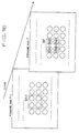
- the principle of the vector quantizer will be described prior to the description of the vector quantizer of Fig. 3. Referring to Fig. 1, assuming that an object has moved on the screen during the period from a frame No. f-1 to a frame No. f from a position A to a position B, then a block S f (R) including a plurality of the lattice samples of an image signal around a position vector R in the frame No. f becomes approximately equal to the block S f-1 (R-r) of the image signal at a position determined by subtracting a movement vector r from a position vector R in the frame No.
- FIG. 3 showing an example of the structure of a proposed experimental vector quantizer of this kind, there are shown an A/D converter 1, a raster/block scan converter 2, a frame memory 3, a movement vector detector 4, a variable delay circuit 5, a subtractor 6, a scalar quantizer 7, an adder 8 and a variable-length encoder 9.
- the A/D converter 1 converts an analog picture input signal 101 into the corresponding digital signal and gives a digital picture signal sequence 102 for raster scanning.
- the serial digital picture signal sequence 102 is converted by the raster/block scan converter 2, and thereby the digital picture signal sequence is converted into a block scan picture input signal 103 arranged sequentially block by block (a raster scan is adopted within each block) from the top to the bottom and from the left to the right on the screen.
- a reproduced picture signal 104 of one frame before regenerated according to inter-frame DPCM loop is read from the frame memory 3.
- the movement vector (u, v) corresponds to the horizontal and the vertical shifts of the picture element of the block of the reproduced picture signal 105 of one frame before.
- the variable delay circuit 5 block-shifts the one-frame preceding reproduced picture signal 104 by the movement vector and gives a predictive picture signal 106 which is the closest to the present block scan picture input signal 103.
- the subtractor 6 calculates the difference between the block scan picture input signal 103 and the predictive picture signal 106 (derived from a preceding frame) and gives a predictive error picture signal 107 to the scalar quantizer 7.
- the scalar quantizer 7 converts the predictive error picture signal 106 into a predictive error quantization picture signal 108 reduced in the number of quantization levels at picture element unit.
- the adder 8 adds the predictive error quantization picture signal 108 and the predictive picture signal 106 and gives a reproduced picture signal 109 including scalar quantization error to the frame memory 3.
- the frame memory performs delaying operation to delay the present reproduced picture signal 109 by one frame.
- the picture input signal 103 is S f (m, n)
- the predictive picture is p f (m, n)
- the predictive error signal 107 is ⁇ f (m, n)
- scalar quantization noise is Q f s (m, n)
- the predictive error quantization signal 108 is ⁇ f (m, n)
- the one-frame preceding reproduced picture signal 104 is ⁇ f-1 (m, n)
- ⁇ f (m, n) S f (m, n) - P f (m, n)
- S ⁇ f-1 (m, n) S ⁇ f (m, n) ⁇ Z -f .
- Z -f denotes delay corresponding to one frame.
- Fig. 5 shows an example of the structure of the movement vector detector 4 for carrying out movement compensation.
- a deviation computation circuit 10 a movement region line memory 11, a line memory control circuit 12, a deviation comparator 13 and a movement vector latch 14.
- the movement vector detector 4 gives S f (R) produced by blocking a plurality of the sequences of the present picture input signal 103 to the deviation computation circuit 10.
- the lines of the one-frame preceding reproduced picture signal 104 stored in the frame memory 3 corresponding to the tracking range of the movement region of S f (R) are stored in the movement region line memory 11.
- the line memory control circuit 12 sends sequentially the blocks adjacent to a plurality of blocks S f-1 (R+r) of the one-frame preceding reproduced image signal 104 to the deviation computation circuit 10.
- the deviation computation circuit 10 computes the deviation L(u, v) of the blocks in the neighborhood of S f (R) and S f-1 (R-r) and the deviation comparator 13 determines the minimum deviation min L(u, v). Since u and v corresponds to the horizontal u,v and the vertical address shifts of blocks in the movement region line memory 11 respectively, the deviation comparator 13 gives a movement detection strobing signal 111 to the movement vector latch 14 when the deviation is minimized, to take in a movement vector address 112.
- the movement vector latch 14 sends the displacement r of S f-1 (R-r) relative to S f (R) minimizing the deviation L(u, v) as the movement vector 105 to the variable delay circuit 5 and the variable-length encoder 9 of Fig. 3.
- variable-length encoder 9 of Fig. 3 processes the movement vector 105 and the predictive error quantization signal 108 through variable-length encoding to reduce the amount of information of the picture signal.
- the variable-length encoding enables the transmission of the movement compensation inter-frame encoding output 110 at a low bit rate.
- the movement compensation operation is performed for every block and the inter-frame DPCM operation is performed for every picture element. Accordingly, it is impossible to discriminate between a minute variation of the picture and noise, and the variable-length encoding of the movement vector and the predictive error quantization signal is difficult. Furthermore, since the control of the variation of the quantity of produced information depending on the movement scalar is difficult, a large loss is inevitable when transmission is carried out through a transmission channel of a fixed transmission capacity. Still further, encoding the predictive error quantization signal for every picture element is inefficient. Since the movement compensation system is liable to be affected by transmission channel error, the frame memory needs to be reset or repeated transmission when transmission channel error occurs, which requires long resetting time.
- An object of the present invention is to provide a vector quantizer capable of efficiently encoding a compensation predictive error signal at a reduced bit rate by performing adaptive vector quantization after judging the significance of the compensation predictive error signal in blocks, and capable of movement compensation inter-frame vector encoding in which variable-length encoding of movement vector is facilitated and information production control is achieved easily.
- Further object of the present invention is to provide a vector quantizer capable of preventing the accumulation of vector quantization errors by inserting a low pass filter in the output of a frame memory and changing over the mode to vector-quantize the blocks themselves of a picture signal sequence instead of the blocks of a predictive error signal when the correlation between successive framed is very low, and capable of restricting the sudden increase of vector quantization error even when the frame changes greatly.
- Fig. 6 is a block diagram showing the structure of an embodiment of the vector encoder according to the present invention.
- FIG. 6 there are shown a multiaccess frame memory 20, an adaptive vector quantization encoder 21 and an adaptive vector quantization decoder 22.
- parts designated by the same reference characters as those used in Fig. 3 are the same or like parts as those of Fig. 3.
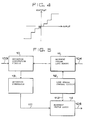
- Figs. 7 and 8 are block diagrams showing the respective structure of embodiments of the adaptive vector quantization encoder and the adaptive vector quantization decoder which are used in the present invention respectively.
- a mean value separation circuit 23 a normalization circuit 24, a significance decision circuit 25, an output vector address counter 26, an output vector code table 27, two deviation computation circuits 28, a minimum deviation detector 29, two index latches 30, a mean value correction circuit 32, an amplitude regeneration circuit 31 and a regenerative vector register 33.
- a normalization circuit 24 a significance decision circuit 25
- an output vector address counter 26 an output vector code table 27
- two deviation computation circuits 28 a minimum deviation detector 29, two index latches 30
- a mean value correction circuit 32 an amplitude regeneration circuit 31 and a regenerative vector register 33.
- a raster/block scanning converter 2 gives a block scan picture input signal 103 to a movement vector detector 4 and a block scan picture input signal 120 (delayed by several lines so that the block scan picture input signal will not overlap a movement compensation region) to a subtractor 6, for inter-frame vector encoding.
- a movement vector detector 4 obtains a movement vector 105 (through the same procedure as described in connection with Figs. 3 and 5) on the basis of the picture input signal 103 and a preceding neighbor frame reproduced picture signal 121 and controls a variable delay circuit 5 so that the variable delay circuit 5 gives a predictive picture signal 122 corresponding to the position of the block scan picture input signal 120 to a subtractor 6.
- the output signals of the subtractor 6, i.e., predictive error picture signals 123 are connected into blocks and are vector-quantized through the adaptive vector quantization encoder 21 and the adaptive vector quantization decoder 22.
- the predictive error picture signal 123 is vector-quantized to provide a predictive error vector quantization picture signal 125 containing vector-quantized noises.
- An adder 8 adds the predictive error vector quantization picture signal 125 and the predictive picture signal 122 and gives a reproduced picture signal 126.
- the reproduced picture signal 126 is written in the multiaccess frame memory 20 to be used for a movement compensation of the next frame.
- each block is defined by a picture element vector.
- the picture input signal 120 is S f l
- the predictive picture signal 122 is P f l
- the predictive error signal 123 is ⁇ f l
- the predictive error vector quantization signal 125 is ⁇ f l
- the vector quantization noise is Q f l
- the reproduced picture signal 126 is ⁇ f l
- the preceding neighbor reproduced picture signal 121 is where l indicates the block sequence number
- the predictive picture signal 122 undergoes movement compensation process and is formed by cutting out a block shifted so that the deviation is minimized from the preceding neighbor regenerative signal 121.
- the block of the predictive picture signal 122 cut out and formed through movement compensation need not coincide with a block dealt with by inter-frame vector coding in boundary and block size.
- the movement compensation is performed in a sliding block matching mode while inter-frame vector encoding is performed in a fixed block mode.
- the adaptive vector quantizer comprises a cascaded connection of the adaptive vector quantization encoder 21 and the adaptive vector quantization decoder 22.
- the predictive error picture signal l [ ⁇ 1, ⁇ 2, ..., ⁇ k ] arranged in blocks is obtained, as shown in Fig. 9, by subtracting each dimension of the blocks P l of the predictive picture signal from the blocks S l of the picture input signal.
- the predictive error picture signal l is subjected to conversion to execute significance decision and adaptive vector quantization.
- X j ( ⁇ j - ⁇ l )/ ⁇ l
- X l [X1, X2, ..., X k ] That is, the mean value ⁇ l is separated and normalized with respect to the amplitude factor ⁇ l to obtain the input vector X l .
- the output vector y i is converted into a predictive error vector quantization picture signal ⁇ l through the following reverse conversion.
- ⁇ j ⁇ l ⁇ y ij + ⁇ l
- l O when ⁇ l ⁇ T1 and ⁇ l ⁇ T2.
- T1 and T2 defines a threshold 128 for the level decision of ⁇ l .
- the significance of the predictive error picture signal is decided in blocks and the predictive error picture signal is subjected to mean value separation and amplitude normalization to vector-quantize the signal only when the level of the picture signal changes between frames of a predetermined level after movement compensation. When the level of the picture signal is below the predetermined level, there is no movement or the picture can entirely be regenerated through movement compensation.
- the information production can be held at a fixed amount by controlling the threshold 128 of T1 and T2.
- X [X1, X2, ..., X k ] is an input vector in k-dimensional signal space R k
- R1, R2, ..., R N are N partitions of R k
- vector quantization V Q is given by the cascaded connection of encoding C and decoding D.
- V Q (x) y i , if x R i C : X ⁇ i, if d(x, y i ) ⁇ d(x, y j ) for all j D : i ⁇ y i
- Deviation measurement d(x, y i ) indicates the separation between the input and the output vectors in the k-dimensional signal space and absolute deviation measurement is
- the data rate of the index i which is the vector quantization coding output at this time, is K ⁇ 1log2N bits/picture element.
- Decoding is achieved simply by conversion into output vector y i corresponding to the index i.
- the set Y of output vectors y i may be obtained either by clustering training of the actual input vectors x of by a predetermined input vector probability model.
- Fig. 10 shows the relation input vectors and output vectors.
- the adaptive vector quantization coding outputs are significance decision index ⁇ l , mean value ⁇ l , amplitude factor ⁇ l and output vector index i.
- the predictive error picture signal 123 is processed in blocks through the mean value separation circuit 23 and the normalization circuit 24 to be mean value separation normalized and input vector 129 is sent to the deviation computation circuit 28.
- the output vector address counter 26 counts up sequentially and reads the output vector 131 from the output vector code table 27.
- the deviation computation circuit 28 computes the deviation d(x, y i ) between the input vector and the output vector and sends the deviation 132 from each output vector to the minimum deviation detector 29.
- the minimum deviation detector 29 gives strobing signal 133 so that the output vector address 134 of the output vector address counter 26 corresponding to the index of the output vector is stored in the index latch, when the minimum deviation between the output vector and the input vector is detected.
- the index latch 30 gives the index of the output vector which has the minimum deviation with respect to the input vector.
- the significance decision circuit 25 gives, on the basis of the mean value of the blocks of the predictive error picture signal 123 and the amplitude factor, a significance decision identification index and, when significant, the mean value and the amplitude gain.
- the output signals 124 of the adaptive vector quantization encoder are significance decision index, and, if significant, the mean value of the predictive error picture signal, the amplitude factor and the output vector index.
- an output vector corresponding to the output vector index is read from the output vector code table 34 and the amplitude regenerative circuit 31 and the mean value correction circuit 32 compute a predictive error vector quantization picture signal when significant.
- the regenerative vector register 33 resets the contents to zero when the significance decision identification index indicates insignificance and finally gives the predictive error vector quantization picture signal 125.
- the inter-frame vector encoding process and the movement compensation process are controlled by the multi-access frame memory 20, the movement vector detector 4 and the variable delay circuit 5 so that those processes do not overlap each other in respect of time.
- the movement compensation inter-frame adaptive vector quantized coded data are the movement vector 105, the significance decision index, and, if significant, the predictive error picture signal mean value, the amplitude factor and the output vector index. These data are subjected to variable-length encoding in the variable-length encoder 9 of Fig. 6 and sent out as the movement compensation inter-frame vector coded output 127 to the transmission segment.
- Block size for executing the block matching of movement compensation and block size for vector quantization desirably are the same both in horizontal direction and in vertical direction or are related by integer multiple. In such a condition, it is advantageous that the movement vector and the adaptive vector coded output can be subjected to variable-length coding together in block to block correspondence. Furthermore, since the amount of information produced becomes more correspondent to movement, coding is facilitated. Still further, the transmission of a fixed amount of information is possible through the feedback control of the significance decision threshold for adaptive vector quantization.
- This embodiment is a vector quantizer capable of highly efficiently encoding picture signals by utilizing the correlation between successive picture frames according to the vector quantization method.
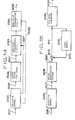
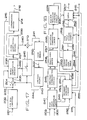
- FIG. 12 is a block diagram showing an encoder.
- a digitized picture signal at 201 a raster/block scan converter for converting the picture signal sequence arranged along the direction of raster scanning into blocks each including a plurality of samples at 202, blocked picture signal sequence at 203, a subtractor at 204, the predictive error signal sequence of the blocked picture signal at 205, a movement detection vector quantization at 206, a vector quantization coded output at 207, a vector quantization decoder at 208, vector quantization decoded output, i.e., reproduced predictive error signal sequence, at 209, an adder at 210, the block of reproduced picture signal sequence at 211, a frame memory at 212, the block of reproduced picture signal sequence delayed by one frame cycle, which also is the block of predictive signal sequence for predicting the block of the picture signal sequence 203, at 213, a transmission buffer at 214, feedback control signal at 215 and encoder output at 216.
- a raster/block scan converter for converting the picture signal sequence arranged along the direction of rast
- Fig. 13 shows an exemplary constitution of the vector quantization encoder 206 in detail.
- a mean value separation circuit at 217 an amplitude normalization circuit at 218, the inter-frame difference of the block of the picture signal sequence normalized with respect to amplitude after mean value has been separated at 219, mean value calculated by the mean value separation circuit 217 at 220, amplitude calculated by the amplitude normalization circuit 210 at 221, a movement detecting circuit which decides, on the basis of the mean value 220 and the amplitude factor 221, whether or not the blocked picture signal sequence being processed presently has made significant change with respect to the block of the one-frame cycle preceding picture signal sequence of the same position at 222, the result of decision of the movement detecting circuit 222 at 223, code table address counter at 224, code table index at 225, output vector code table memory at 226, code table output vector at 227, a deviation computation circuit at 228, a minimum deviation detecting circuit at 229, a minimum deviation indicating signal at 230 and
- Fig. 14 shows an exemplary constitution of the vector quantization decoder 208 in detail.
- a reception latch at 232 there are indicated a reception latch at 232, an amplitude regenerating circuit at 233 and a mean value regenerating circuit at 234.
- Fig. 15 shows an exemplary embodiment of the decoder for decoding the processed signal.
- indicated at 235 is a reception buffer
- at 236 is a block/raster scan converter functioning reciprocally to the raster/block scan converter 202 and at 237 is regenerative picture signal sequence.
- the encoder is based on the conception of the inter-frame DPCM system.
- the digitized picture signal sequence 201 is regarded as a group of samples arranged in a square lattice, however, input is given in the order of raster scanning.
- the raster/block scan converter 202 partitions the picture signal sequence 201 into blocks as shown in Fig. 16 and gives output signals corresponding to the blocks.
- ⁇ f is the difference 205 between the signal source vector 203 calculated by the subtractor 204 and the block 213 of the predictive signal sequence
- ⁇ f is the block 209 of the reproduced differential signal sequence formed by the vector quantization encoder 206 and the vector quantization decoder 208
- ⁇ f is the block 211 of the reproduced signal sequence
- P f is the predictive signal sequence 213 given by the frame memory 212.
- the vector quantization coded output 207 obtained through the process stated above is the difference between the signal source vector 203 and the block 213 of the predictive signal sequence, namely, the result obtained by data-compressing the block 205, ⁇ f , of the predictive error signal by the vector quantization encoder 206.
- the vector quantization coded output 207 is sent to the transmission buffer 214, and then given to the transmission channel as the encoder output.
- the actions of the vector quantization encoder 206 and the vector quantization decoder 208 will be described hereinafter in connection with Figs. 13 and 14.
- a block consisting of k pieces of samples (k: the plural number) is given as an input vector in a k-dimensional signal space, output vectors having minimum deviation with respect to the input vectors given sequentially are selected among a set of output vectors prepared beforehand on the basis of the probability distribution density of the input vector the deviation with respect to the input vector will generally be minimized, and the index attached to the selected output vector is given as a quantized output.
- decoding it is only to read an output vector corresponding to the index from the same set provided also in the decoder.
- the following formulas for instance, may be employed.
- the mean value separation normalization process distribute the input vector random within a limited range in the k-dimensional signal space, which improves the efficiency of vector quantization.
- This process requires the preparation of the set of output vector on the basis of the input vector distribution processed through the mean value separation normalization and the process reverse to the mean value separation normalization including amplitude regeneration and mean value regeneration, after reading the output vector in the decoding process.
- Mean value separation normalizing output vector prepared on the basis of the probability distribution density of the mean value separation normalizing input vector so that the deviation from the mean value separation normalizing input vector is generally minimized is stored in the code table memory 226.
- the deviation computation circuit 228 computes the deviation of the mean value separation normalizing input vector x from the mean value separation normalizing output vectors 227 y i .
- the minimum deviation detecting circuit 229 calculates d( x , y i ) sequentially and gives a strobing signal 230 when a value smaller than the past minimum deviation is obtained.
- the latch 231 stores the index 225.
- the index i of a mean value separation normalizing output vector which has the minimum deviation with respect to the mean value separation normalizing input vector is stored in the latch 231.
- This index, the mean value 220 ( ⁇ ) and the amplitude factor 221 ( ⁇ ) are the vector quantization coded outputs, however, the data is compressed further by utilizing the correlation between successive picture frames.
- the center of the distribution thereof is a zero vector. Therefore, the amount of data 15 reduced greatly by regarding the input vectors distributed in the vicinity of the zero vector as the zero vector and without sending our indices, the mean value and the amplitude factor.
- the movement detecting circuit 222 receives the mean value 220 ⁇ and the amplitude factor 221 ⁇ and decides whether or not the blocks of the predictive error signal sequence can be regarded as zero vectors, namely, whether or not any significant change (movement) as compared with the one-frame cycle preceding frame has occurred in the present block, for example, according to the following criterion: when ⁇ ⁇ T ⁇ and ⁇ ⁇ T ⁇ , significant change has not occurred, and when ⁇ > T ⁇ and ⁇ > T ⁇ , significant change occurred, where T ⁇ is a threshold.
- the latch 231 gives only a signal indicating "no movement” when a code indicating "no movement” is given as the result of movement detection and gives the index 225, the mean value 220 and the amplitude factor 221 in addition to a signal 223 indicating "movement” when a code indicating "movement” is given, as a vector quantization coded output 207.
- the transmission buffer 214 monitors the amount of information transmitted controls the threshold T ⁇ on the basis of the feedback control signal 215. Thus the amount of information to be transmitted is controlled.
- mean value separation normalizing output vectors 227 y i are read out according to the index i from the code table memory 226 and are multiplied by the amplitude factor 221 at the amplitude regenerating circuit 233.
- the reception buffer 234 receives the output 216 of the encoder and decodes the vector quantization coded output signal 207.
- Q vector quantization error
- Z -f is delay of one-frame cycle.
- the block/raster converter 236 scans blocked regenerative picture signal sequence 211 ⁇ f along the raster scanning direction to convert the same into a reproduced picture signal sequence 237.
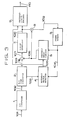
- Fig. 17 shows an exemplary embodiment of the embodiment of an encoder according to the present invention.
- 201 is a digitized picture signal
- at 202 is a raster/block scan converter
- at 203 is a blocked picture signal sequence
- at 204 is a subtractor
- at 205 is the predictive error signal sequence of the blocked picture signal
- at 238 is a movement detection vector quantization encoder
- at 207 is a vector quantization coded output
- at 239 is vector quantization decoder
- at 240 is a vector quantization decoded output
- at 210 is an adder
- at 241 are blocks of reproduced picture signal sequence
- at 212 is a frame memory
- at 242 are blocks of a reproduced picture signal sequence delayed by one-frame cycle
- at 243 is a low-pass filter
- at 244 are blocks given by filtering the blocks 242 of the delayed reproduced picture signal sequence through the low-pass filter 243 and are also blocks of a predictive signal sequence for predicting the blocks
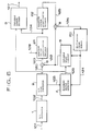
- Fig. 18 shows the detail of an exemplary embodiment of the movement detection vector quantization encoder 238.
- indicated at 247 is a parallel mean value separation circuit
- at 248 is a parallel amplitude normalization circuit
- at 249 is the mean value of the blocks 203 of the picture signal sequence
- at 250 is the mean value of the blocks 205 of the predictive error signal sequence
- at 251 is the intra-block amplitude factor of the blocks 203 of the picture signal sequence
- at 252 is the intra-block amplitude factor of the blocks 205 of the predictive error signal sequence
- at 253 is a movement detection circuit
- at 254 is either the mean value 249 or the mean value 250 chosen by the movement detection circuit 253
- at 255 is either the intra-block amplitude factor 251 or the intra-block amplitude factor 252
- at 246 is a signal corresponding to the result of decision of the movement detection circuit 253,
- at 256 is a switch for changing over between the blocks of the picture signal sequence through mean value separation normalization and
- Fig. 19 shows the detail of an exemplary embodiment of the vector quantization decoder 239.
- indicated at 263 is a reception latch
- at 233 is an amplitude regenerating circuit
- at 234 is a mean value regenerating circuit.
- Fig. 20 shows an example of the structure of the decoder included in this embodiment for decoding a processed signal.
- indicated at 235 is a reception buffer, at 236 is a block/raster scan converter and at 237 is a reproduced picture signal sequence.
- a digitized picture signal sequence 201 is a sequence of samples given sequentially along raster scanning direction.
- the raster/block scan converter 202 partitions the picture signal sequence into blocks and scans and converts the picture signal sequence sequentially in blocks.
- ⁇ f is the difference 205 between a signal source vector 203 calculated by the subtractor 204 and the block 244 of the predictive signal sequence
- ⁇ f is the block 209 of the reproduced differential signal sequence formed by the vector quantization encoder 238 and the vector quantization decoder 239
- ⁇ f is the block 241 of the reproduced picture signal sequence
- P f is the predictive signal sequence 244
- Q is vector quantization error
- Z -f delay of one-frame cycle caused
- P f is a signal resulting from the elimination of high frequencies from the reproduced signal sequence ⁇ f-1 of the blocks S f-1 of the picture signal sequence at the same position in the frame one-frame cycle before the present frame, i.e., the frame No. f-1.
- the vector quantization error are such as granular noises appearing in the high-frequency band. Therefore, the low-pass filter 243 prevents the accumulation of the quantization error and always acts so that high-quality pictures are obtained.
- the switch 245 is closed and the block 244 of the predictive signal sequence is applied to the adder 210.
- the power of the block 205 of the predictive error signal sequence becomes very large when the picture changes greatly, which increases the vector quantization error.
- this embodiment is designed to subject the block S f of the picture signal sequence to vector quantization encoding as it is instead of the block ⁇ f of the predictive error signal sequence, when the picture changes greatly, namely, when the power of the predictive error signal increases.
- the control signal 246 opens the switch 245, the adder 210 allows substantially the vector quantization decoded output 240 to pass through and to become the block 241 of the reproduced picture signal sequence as it is.
- the movement detection vector quantization encoder 238 makes the decision of changeover and the changeover operation. These operations will be described in detail afterward.
- the vector quantization coded output 207 is sent to the transmission buffer 214 and is sent out to the transmission channel as the encoder output 216.
- the block 203 S f of the picture signal sequence and the block 205 P f of the predictive error signal sequence are given as input signals.
- the parallel mean value separation circuit 247 subtracts the mean value 249 ⁇ s and ⁇ ⁇ operated by the use of the following formulas: from the blocks S f and P f respectively. Furthermore, those blocks are normalized by the parallel amplitude normalizing circuit 248 with respect to the amplitude factors 251 ⁇ s and 252 ⁇ ⁇ operated by the following formulas: These processes form mean value separation normalized vectors x s and x ⁇ .
- Amplitude calculating methods other than those described above are available. Those alternative methods are, for instance, The mean value separation normalizing process distributes the input vectors random within a limited range in a k-dimensional signal space, which improves vector quantization efficiency.
- the decision is made, for example, by comparing ⁇ ⁇ and ⁇ ⁇ with a threshold T ⁇ that movement has occurred ( ⁇ f ⁇ O ) when ⁇ ⁇ ⁇ T ⁇ and ⁇ ⁇ ⁇ T ⁇ and movement has not occurred ( ⁇ f ⁇ O ) when ⁇ ⁇ > T ⁇ or ⁇ ⁇ > T ⁇ .
- the threshold T ⁇ is controlled by the feedback control signal 215 given by the transmission buffer 214 so that the amount of information to be transmitted is fixed.
- the movement detector 253 has, in addition to the above-mentioned function, a function to made decision for changing over the input vectors to the blocks S f of the picture signal sequence as described above when the movement is very large.
- This decision is made on an assumption that the movement has been detected through the above-mentioned process, on the basis of the following conditions: ⁇ f is selected as input vector when ⁇ ⁇ ⁇ ⁇ s and S f is selected as input vector when ⁇ ⁇ > ⁇ s .
- This changeover process is based on a conception that ⁇ s and ⁇ ⁇ represent approximately the respective powers of those signals. This is because the smaller the power of signal for vector quantization, the smaller is the vector quantization error of the reproduced signal.
- the movement detection circuit 253 gives the result of the decision as the signal 246 and the changeover switch 256 connects either the mean value separation normalized input vector x s or x ⁇ to the next deviation computing circuit 228 according to the signal 246.
- the movement detection circuit 253 gives, according to the result of the decision, the mean value ( ⁇ ) 254 and the amplitude factor 255 of the selected vector.
- Mean value separation normalized output vectors prepared on the basis of the probability distribution density of the mean value separation normalized input vectors so that the deviation thereof from the mean value separation normalized input vectors is minimized generally are stored beforehand in the code table memory 260 at different addresses corresponding to the distributions of S f and ⁇ f .
- the index i includes not only the information indicating the code table address but also the information indicating whether the vector indicated by the index i is for S f or for ⁇ f .
- the distortion computing circuit 228 computes the distortion of the mean value separation normalized input vector 257 x from the mean value separation normalized output vector 261 y i .
- the minimum deviation detection circuit 229 gives the strobing signal 230 when the deviation d( x , y i ) calculated sequentially are smaller than the past minimum deviation.
- the index i of a mean value separation normalized output vector which gives the minimum deviation for x is stored in the latch 262.
- the latch 262 gives, according to the output signal 246 of the movement detection circuit 253, a signal indicating "no movement” when the signal 246 indicates “no movement” and the index, the mean value 254 and the amplitude factor 255 in addition to a signal indicating "movement” as the vector quantization encoded output 207 when the signal 246 indicates "movement”.
- the latch 263 (Fig. 19) of the vector quantization decoder 239 receives the vector quantization coded output 207.
- the latch 263 decides from the index i which one of S f and ⁇ f is vector-quantized and gives a signal equivalent to the output 246 of the movement detection circuit.
- the latch reads, according to the index 259, the mean value separation normalized output vector 261 y i from the code table memory 260
- the amplitude regenerating circuit 233 multiplies the output vector y i by the amplitude factor 255 and the mean value regenerating circuit 234 adds the mean value 254 to regenerate the output vector.
- the reception buffer 235 receives the encoder output 216 and decode the vector quantization encoder output signal 207.
- the vector quantization decoder 239 produces, as mentioned above, the output vector 240.
- the switch 245 is closed when the signal 246 indicates "movement" or "no movement” and the coded vector is ⁇ f , and the block 241 S f of the reproduced picture signal sequence by the adder 210 and the frame memory 212, in the manner as expressed by the following formulas:
- P ⁇ f F ⁇ ( S ⁇ ⁇ f ⁇ Z -f )
- Q vector quantization error
- Z -f delay of one-frame cycle caused by the frame memory 212
- F is the elimination of high-frequency band by the low-pass filter 243.
- the switch 245 is opened to let the decoded S f through the adder 210.
- the blocks/raster converter 236 scans the blocks 241 ⁇ f of the blocked reproduced picture signal sequence along the raster scanning direction to convert, the reproduced picture signal sequence into the reproduced picture signal sequence 237.
- the respective amplitudes of ⁇ f and S f are compared to change over the input vector to be coded between ⁇ f and S f , however, the input vector may be changed over between ⁇ f and S f by comparing the amplitude of ⁇ f with that of P f .
- the input vector is ⁇ ⁇ f when ⁇ ⁇ ⁇ ⁇ p , or S ⁇ f when ⁇ ⁇ > ⁇ p where ⁇ p is the amplitude of P f .
- this invention is applicable to shortening the code length, namely, to preventing the increase of the amount of information, by limiting the code table address to be searched, when sudden movement is detected.
Landscapes
- Engineering & Computer Science (AREA)
- Multimedia (AREA)
- Signal Processing (AREA)
- Physics & Mathematics (AREA)
- General Physics & Mathematics (AREA)
- Theoretical Computer Science (AREA)
- Computer Vision & Pattern Recognition (AREA)
- Compression Or Coding Systems Of Tv Signals (AREA)
- Compression, Expansion, Code Conversion, And Decoders (AREA)
Claims (7)
- Vidéocodeur à prédiction inter-trames comprenant un détecteur de vecteur de mouvement (4) qui délivre en sortie un vecteur de mouvement (105) représentatif du mouvement dans la direction horizontale et verticale d'un bloc de signal d'image précédent qui est le plus analogue à un bloc de signal d'entrée présent, un codeur à longueur variable (9) et une boucle de système MIC différentiel comportant un soustracteur (6), un quantificateur (7), un additionneur (8) et une mémoire de trames (3, 20), caractérisé en ce que le quantificateur est mis en oeuvre par un codeur de quantification vectorielle adaptative (21) suivi d'un décodeur de quantification vectorielle adaptative (22); le codeur de quantification vectorielle (21) traitant le signal de sortie (123 sur les figures 6 et 7) du soustracteur (6) en blocs et comprenant un circuit de séparation de la valeur moyenne (23) et un circuit de normalisation d'amplitude (24) servant à obtenir une valeur moyenne, un facteur d'amplitude et un vecteur d'entrée (129) à partir du signal de sortie (123) du soustracteur (6), ledit facteur d'amplitude étant déterminé par la différence entre ledit signal de sortie (123) et ladite valeur moyenne; un circuit de détermination de poids (25) qui reçoit des valeurs de seuil (128), compare la valeur moyenne et le facteur d'amplitude auxdites valeurs de seuil et délivre en sortie un indice de détermination de poids; un circuit de calcul d'écart (28) et un détecteur d'écart minimum (29) pour détecter l'écart minimum entre ledit vecteur d'entrée (129) et un vecteur de sortie (131) extrait d'une table de codes de vecteurs de sortie (27); un verrou d'indices (30) pour recevoir la sortie dudit détecteur d'écart minimum (29) sous la forme d'un signal de strobage (133) de manière telle que l'adresse (134) de ladite table de codes de vecteurs de sortie (27) est enregistrée en tant qu'indice de vecteur de sortie dans ledit verrou d'indices lorsque l'écart minimum entre ledit vecteur de sortie (131) et ledit vecteur d'entrée (129) est détecté; ledit codeur à longueur variable (9) codant ledit vecteur de mouvement (105) et ledit indice de détermination de poids, ladite valeur moyenne, ledit facteur d'amplitude et ledit indice de vecteur de sortie si la valeur de seuil (128) est dépassée, mais ne codant que ledit vecteur de mouvement et ledit indice de détermination de poids lorsque ladite valeur de seuil (128) n'est pas dépassée.
- Vidéocodeur selon la revendication 1, caractérisé en ce que ladite table de codes de vecteurs de sortie (27) enregistre un ensemble de vecteurs de sortie produits au préalable sur la base d'un modèle de probabilité desdits vecteurs d'entrée.
- Vidéocodeur selon la revendication 1 ou 2, caractérisé en ce que ledit décodeur de quantification vectorielle adaptative (22) qui reçoit la sortie (124) dudit codeur de quantification vectorielle adaptative (21), lit un vecteur de sortie correspondant à l'indice de vecteur de sortie en provenance de la table de codes de vecteurs de sortie (27) présentant le même contenu que celui du codeur de quantification vectorielle adaptative (21), multiplie le vecteur de sortie par ledit facteur d'amplitude et ajoute ladite valeur moyenne au produit pour régénérer le bloc de signal d'image à quantification vectorielle d'erreur de prédiction, et donne un bloc de signal d'image à quantification vectorielle d'erreur de prédiction égal à zéro lorsque l'indice de détermination de poids indique que le bloc de signal d'image à quantification vectorielle d'erreur de prédiction n'est pas significatif.
- Vidéocodeur à prédiction inter-trames comprenant un circuit de détection de mouvement (222, 253), une unité de transmission (214), une boucle de système MIC différentiel traitant une séquence de signal d'image sous la forme de blocs (203) et comportant un soustracteur (204), un quantificateur (206, 238), un additionneur (210) et une mémoire de trames (212), caractérisé en ce que ledit quantificateur est un codeur de quantification vectorielle comprenant un circuit de séparation de valeur moyenne (217, 247) et un circuit de normalisation d'amplitude (218, 248) pour obtenir une valeur moyenne (220, 249, 250, 254), un facteur d'amplitude (221, 251, 252, 255) et un vecteur d'entrée (219, 257) à partir du signal de sortie (205) du soustracteur (204), ledit facteur d'amplitude étant déterminé par la différence entre ledit signal de sortie et ladite valeur moyenne, et un circuit de détection de mouvement (222, 253) qui décide, sur la base d'une comparaison entre une valeur de seuil et ladite valeur moyenne (220, 249, 250) et ledit facteur d'amplitude (221, 251, 252) respectivement si ou non le signal d'image en blocs (203) faisant couramment l'objet du traitement a changé d'une manière significative par rapport à la trame précédente et délivre en sortie, en tant que résultat de sa décision, un signal (223, 246) indiquant un mouvement ou une absence de mouvement, et un circuit de calcul d'écart (228) et un détecteur d'écart minimum (229) pour détecter l'écart minimum entre ledit vecteur d'entrée (219, 257) et un vecteur de sortie (227, 261) extrait d'une table de codes de vecteurs de sortie (226, 260); un verrou (231, 262) pour recevoir la sortie dudit détecteur d'écart minimum (229) sous la forme d'un signal de strobage (230) de telle manière que l'adresse (259) de ladite table de codes de vecteurs de sortie (226, 260) soit enregistrée en tant qu'indice de vecteur de sortie dans ledit verrou lorsque l'écart minimum entre ledit vecteur de sortie (227, 261) et ledit vecteur d'entrée (219, 257) est détecté, et ladite unité de transmission est un tampon de transmission de sortie (214) qui suit ledit verrou et reçoit et délivre en sortie ledit signal (223, 246), ladite valeur moyenne, ledit facteur d'amplitude et ledit indice de vecteur de sortie si la valeur de seuil (215) est dépassée, mais ne reçoit et ne délivre en sortie ledit signal (223, 246) que lorsque la valeur de seuil (215) n'est pas dépassée, et ledit tampon de transmission (214) produit en outre un signal de commande (215) influençant ladite valeur de seuil de sorte que la quantité d'information envoyée par ledit tampon de transmission est commandée.
- Vidéocodeur selon la revendication 4, caractérisé en ce que le tampon de transmission de sortie (214) traite ledit signal indiquant un mouvement, ledit indice du vecteur de sortie, ladite valeur moyenne et ledit facteur d'amplitude en même temps par l'intermédiaire d'un codage à longueur variable.
- Vidéocodeur selon la revendication 4 ou la revendication 5, caractérisé en ce que le signal d'erreur de prédiction (205) délivré par ledit soustracteur (204) et ledit signal d'image courant fourni audit soustracteur (204) sont tous deux envoyés audit circuit de séparation de valeur moyenne (247) et audit circuit de normalisation d'amplitude (240) et traités par eux, et en ce qu'un interrupteur de commutation (256) est prévu entre ledit circuit de normalisation d'amplitude (248) et ledit circuit de calcul d'écart (228), cet interrupteur étant relié à la sortie dudit circuit de normalisation d'amplitude (248) et commandé par ledit signal (246) indiquant un mouvement ou l'absence de mouvement, de façon à recevoir soit ledit bloc de signal d'erreur de prédiction (205) traité par l'intermédiaire de la séparation de valeur moyenne et de la normalisation, soit le bloc du signal d'image courant (203) traité de même par l'intermédiaire de la séparation de valeur moyenne et de la normalisation, en tant que vecteur d'entrée; et en ce que ladite table de codes de vecteurs de sortie (260) enregistre des ensembles de vecteurs de sortie produits au préalable sur la base d'une densité de répartition de probabilité desdites deux sortes de vecteurs d'entrée de sorte que l'écart entre ledit vecteur d'entrée et ledit vecteur de sortie soit minimisé.
- Vidéocodeur selon les revendications 4 à 6, caractérisé par un décodeur de quantification vectorielle (239) qui reçoit la sortie dudit codeur de quantification vectorielle (238), lit un vecteur de sortie correspondant à l'indice de vecteur de sortie dans une table de codes de vecteurs de sortie présentant le même contenu que celui de la table de codes de vecteurs de sortie (260) du codeur de quantification vectorielle (238), multiplie le vecteur de sortie lu dans la table de codes de vecteurs de sortie (260) par ledit facteur d'amplitude et ajoute ladite valeur moyenne au résultat de ladite multiplication pour obtenir des signaux à décodage de quantification vectorielle, et délivre un bloc zéro (240) lorsque ledit signal (246) indique l'absence de mouvement; un additionneur (210) relié à la sortie dudit décodeur de quantification vectorielle (239) et, via un commutateur (245) commandé par ledit signal (246), à la sortie d'une mémoire de trames (212) dont l'entrée est fournie par la sortie de l'additionneur constituant les blocs reproduits de la séquence de signal d'image, ledit commutateur (245) déconnectant ladite mémoire de trames (212) dudit additionneur (210) lorsque ledit signal (246) indique un mouvement.
Priority Applications (3)
| Application Number | Priority Date | Filing Date | Title |
|---|---|---|---|
| EP91108921A EP0446968B1 (fr) | 1983-09-06 | 1984-09-06 | Quantificateur vectoriel |
| EP91108920A EP0451879B1 (fr) | 1983-09-06 | 1984-09-06 | Quantificateur vectoriel |
| EP91108993A EP0457362B1 (fr) | 1983-09-06 | 1984-09-06 | Quantificateur de vecteurs |
Applications Claiming Priority (16)
| Application Number | Priority Date | Filing Date | Title |
|---|---|---|---|
| JP58163617A JPS6055790A (ja) | 1983-09-06 | 1983-09-06 | ベクトル量子化方式フレ−ム間符号化装置 |
| JP163617/83 | 1983-09-06 | ||
| JP59001669A JPS60146363A (ja) | 1984-01-09 | 1984-01-09 | 動き補償フレ−ム間ベクトル符号化器 |
| JP1669/84 | 1984-01-09 | ||
| JP59006473A JPS60150339A (ja) | 1984-01-18 | 1984-01-18 | 画像のサブサンプルベクトル量子化器 |
| JP6473/84 | 1984-01-18 | ||
| JP14606/84 | 1984-01-30 | ||
| JP59014606A JPS60158787A (ja) | 1984-01-30 | 1984-01-30 | フレ−ム間ベクトル符号化器 |
| JP14607/84 | 1984-01-30 | ||
| JP59014607A JPS60158788A (ja) | 1984-01-30 | 1984-01-30 | 動き補償ベクトル量子化器 |
| JP59017281A JPS60162391A (ja) | 1984-02-02 | 1984-02-02 | 逐次近似ベクトル量子化器 |
| JP17281/84 | 1984-02-02 | ||
| JP32918/84 | 1984-02-23 | ||
| JP59032918A JPS60177782A (ja) | 1984-02-23 | 1984-02-23 | ダイナミツク多段ベクトル量子化器 |
| JP49901/84 | 1984-03-15 | ||
| JP59049901A JPS60194686A (ja) | 1984-03-15 | 1984-03-15 | ダイナミツク多段ベクトル量子化器 |
Related Child Applications (4)
| Application Number | Title | Priority Date | Filing Date |
|---|---|---|---|
| EP91108993.6 Division-Into | 1984-09-06 | ||
| EP91108385.5 Division-Into | 1984-09-06 | ||
| EP91108921.7 Division-Into | 1984-09-06 | ||
| EP91108920.9 Division-Into | 1984-09-06 |
Publications (3)
| Publication Number | Publication Date |
|---|---|
| EP0137314A2 EP0137314A2 (fr) | 1985-04-17 |
| EP0137314A3 EP0137314A3 (en) | 1986-08-20 |
| EP0137314B1 true EP0137314B1 (fr) | 1992-05-13 |
Family
ID=27571445
Family Applications (5)
| Application Number | Title | Priority Date | Filing Date |
|---|---|---|---|
| EP84110641A Expired - Lifetime EP0137314B1 (fr) | 1983-09-06 | 1984-09-06 | Quantificateur de vecteurs pour de l'information image |
| EP91108921A Expired - Lifetime EP0446968B1 (fr) | 1983-09-06 | 1984-09-06 | Quantificateur vectoriel |
| EP91108993A Expired - Lifetime EP0457362B1 (fr) | 1983-09-06 | 1984-09-06 | Quantificateur de vecteurs |
| EP91108920A Expired - Lifetime EP0451879B1 (fr) | 1983-09-06 | 1984-09-06 | Quantificateur vectoriel |
| EP91108385A Withdrawn EP0450664A1 (fr) | 1983-09-06 | 1984-09-06 | Quantificateur de vecteurs pour l'information d'image |
Family Applications After (4)
| Application Number | Title | Priority Date | Filing Date |
|---|---|---|---|
| EP91108921A Expired - Lifetime EP0446968B1 (fr) | 1983-09-06 | 1984-09-06 | Quantificateur vectoriel |
| EP91108993A Expired - Lifetime EP0457362B1 (fr) | 1983-09-06 | 1984-09-06 | Quantificateur de vecteurs |
| EP91108920A Expired - Lifetime EP0451879B1 (fr) | 1983-09-06 | 1984-09-06 | Quantificateur vectoriel |
| EP91108385A Withdrawn EP0450664A1 (fr) | 1983-09-06 | 1984-09-06 | Quantificateur de vecteurs pour l'information d'image |
Country Status (2)
| Country | Link |
|---|---|
| EP (5) | EP0137314B1 (fr) |
| DE (4) | DE3485716D1 (fr) |
Families Citing this family (11)
| Publication number | Priority date | Publication date | Assignee | Title |
|---|---|---|---|---|
| DE3750221T2 (de) * | 1986-10-16 | 1994-11-17 | Mitsubishi Electric Corp | Amplituden-adaptiver vektor-quantisierer. |
| EP0624985B1 (fr) * | 1987-04-28 | 2001-03-14 | Mitsubishi Denki Kabushiki Kaisha | Système pour le codage et le décodage d'images |
| US5285498A (en) * | 1992-03-02 | 1994-02-08 | At&T Bell Laboratories | Method and apparatus for coding audio signals based on perceptual model |
| FI92272C (fi) * | 1992-05-20 | 1994-10-10 | Valtion Teknillinen | Kuvansiirtojärjestelmän tiivistyskoodausmenetelmä |
| EP0576765A1 (fr) * | 1992-06-30 | 1994-01-05 | International Business Machines Corporation | Méthode pour coder des données digitales à l'aide de techniques de quantification vectorielle et dispositif pour mettre en oeuvre cette méthode |
| FI94307C (fi) * | 1993-07-05 | 1995-08-10 | Nokia Oy Ab | Menetelmä ja laite ennustuslohkon hakemiseksi prediktiivisen videonkompression yhteydessä |
| US5499057A (en) * | 1993-08-27 | 1996-03-12 | Sony Corporation | Apparatus for producing a noise-reducded image signal from an input image signal |
| US6285994B1 (en) | 1999-05-25 | 2001-09-04 | International Business Machines Corporation | Method and system for efficiently searching an encoded vector index |
| DE10065783B4 (de) * | 2000-12-30 | 2007-05-03 | Leica Microsystems Cms Gmbh | Verfahren, Anordnung und System zur Ermittlung von Prozessgrößen |
| TWI388218B (zh) * | 2007-10-30 | 2013-03-01 | Nippon Telegraph & Telephone | 影像編碼方法與解碼方法、其程式及記錄有程式的記錄媒體 |
| CN105874717B (zh) * | 2014-01-15 | 2018-02-23 | 安娜卡敦设计公司 | 认知信号转换器 |
Family Cites Families (6)
| Publication number | Priority date | Publication date | Assignee | Title |
|---|---|---|---|---|
| FR2101155B1 (fr) * | 1970-08-31 | 1974-09-20 | Ortf | |
| GB2003001A (en) * | 1977-08-16 | 1979-02-28 | Dennis T | Improvements in methods and apparatus for coding digital television signals |
| US4125861A (en) * | 1977-08-18 | 1978-11-14 | Bell Telephone Laboratories, Incorporated | Video signal encoding |
| GB2050752B (en) * | 1979-06-07 | 1984-05-31 | Japan Broadcasting Corp | Motion compensated interframe coding system |
| US4375650A (en) * | 1981-04-29 | 1983-03-01 | General Electric Company | System for processing video signals |
| DE3382806T2 (de) * | 1982-06-11 | 1996-11-14 | Mitsubishi Electric Corp | Vektorquantisierer |
-
1984
- 1984-09-06 EP EP84110641A patent/EP0137314B1/fr not_active Expired - Lifetime
- 1984-09-06 DE DE8484110641T patent/DE3485716D1/de not_active Expired - Lifetime
- 1984-09-06 DE DE3486397T patent/DE3486397T2/de not_active Expired - Fee Related
- 1984-09-06 EP EP91108921A patent/EP0446968B1/fr not_active Expired - Lifetime
- 1984-09-06 DE DE3486398T patent/DE3486398T2/de not_active Expired - Fee Related
- 1984-09-06 DE DE3486396T patent/DE3486396T2/de not_active Expired - Fee Related
- 1984-09-06 EP EP91108993A patent/EP0457362B1/fr not_active Expired - Lifetime
- 1984-09-06 EP EP91108920A patent/EP0451879B1/fr not_active Expired - Lifetime
- 1984-09-06 EP EP91108385A patent/EP0450664A1/fr not_active Withdrawn
Non-Patent Citations (2)
| Title |
|---|
| B:H: Juang, A.H. Grey, "Multiple stage vector quantisation for speech coding", Proc. Intl. Conf. on A.S.S.P., pp 597-600, Paris (1982) * |
| IEEE, Transactions on Communications, volume COM/28, No. 1, January 1980, page 84 * |
Also Published As
| Publication number | Publication date |
|---|---|
| DE3485716D1 (de) | 1992-06-17 |
| EP0450664A1 (fr) | 1991-10-09 |
| EP0451879A2 (fr) | 1991-10-16 |
| DE3486396T2 (de) | 1996-02-01 |
| DE3486397D1 (de) | 1995-08-10 |
| DE3486396D1 (de) | 1995-08-10 |
| EP0137314A3 (en) | 1986-08-20 |
| EP0446968A3 (en) | 1993-03-17 |
| EP0446968A2 (fr) | 1991-09-18 |
| DE3486398T2 (de) | 1995-12-07 |
| EP0457362B1 (fr) | 1995-07-05 |
| EP0137314A2 (fr) | 1985-04-17 |
| EP0451879B1 (fr) | 1995-07-05 |
| DE3486398D1 (de) | 1995-08-10 |
| EP0446968B1 (fr) | 1995-07-05 |
| DE3486397T2 (de) | 1996-01-04 |
| EP0451879A3 (en) | 1992-12-23 |
| EP0457362A1 (fr) | 1991-11-21 |
Similar Documents
| Publication | Publication Date | Title |
|---|---|---|
| US4670851A (en) | Vector quantizer | |
| US5592228A (en) | Video encoder using global motion estimation and polygonal patch motion estimation | |
| US4851906A (en) | Data compression using orthogonal transform and vector quantization | |
| US6008852A (en) | Video coder with global motion compensation | |
| EP0411675B1 (fr) | Dispositif de codage intertrame | |
| US5299019A (en) | Image signal band compressing system for digital video tape recorder | |
| KR910000707B1 (ko) | 화상 부호화 전송방법 및 장치 | |
| US5150209A (en) | Hierarchical entropy coded lattice threshold quantization encoding method and apparatus for image and video compression | |
| EP0624035A1 (fr) | Système pour le codage et le décodage d'images | |
| EP0903945A2 (fr) | Système et méthode de codage intertrame | |
| GB2287153A (en) | Noise reduction apparatus | |
| EP0137314B1 (fr) | Quantificateur de vecteurs pour de l'information image | |
| EP0260721B1 (fr) | Procédé et appareil de codage des signaux d'images à mouvements | |
| US7139314B2 (en) | Inter-frame predicted image synthesizing method | |
| US6101278A (en) | System for extracting coding parameters from video data | |
| JPH04219074A (ja) | 画像符号化装置 | |
| CA1292057C (fr) | Appareil de codage et de transmission d'image | |
| Bage | Interframe predictive coding of images using hybrid vector quantization | |
| CA1248237A (fr) | Quantificateur vectoriel | |
| JPS59148478A (ja) | ベクトル量子化方式フレ−ム間符号化装置 | |
| JPH0787582B2 (ja) | 画像符号化伝送装置 | |
| JPH03143182A (ja) | 処理量適応型画像符号化方式 |
Legal Events
| Date | Code | Title | Description |
|---|---|---|---|
| PUAI | Public reference made under article 153(3) epc to a published international application that has entered the european phase |
Free format text: ORIGINAL CODE: 0009012 |
|
| AK | Designated contracting states |
Designated state(s): DE FR GB NL |
|
| RTI1 | Title (correction) | ||
| PUAL | Search report despatched |
Free format text: ORIGINAL CODE: 0009013 |
|
| RTI1 | Title (correction) | ||
| AK | Designated contracting states |
Kind code of ref document: A3 Designated state(s): DE FR GB NL |
|
| 17P | Request for examination filed |
Effective date: 19861001 |
|
| 17Q | First examination report despatched |
Effective date: 19890126 |
|
| GRAA | (expected) grant |
Free format text: ORIGINAL CODE: 0009210 |
|
| AK | Designated contracting states |
Kind code of ref document: B1 Designated state(s): DE FR GB NL |
|
| XX | Miscellaneous (additional remarks) |
Free format text: TEILANMELDUNG 91108385.5 EINGEREICHT AM 06/09/84. |
|
| REF | Corresponds to: |
Ref document number: 3485716 Country of ref document: DE Date of ref document: 19920617 |
|
| ET | Fr: translation filed | ||
| PLBE | No opposition filed within time limit |
Free format text: ORIGINAL CODE: 0009261 |
|
| STAA | Information on the status of an ep patent application or granted ep patent |
Free format text: STATUS: NO OPPOSITION FILED WITHIN TIME LIMIT |
|
| 26N | No opposition filed | ||
| PGFP | Annual fee paid to national office [announced via postgrant information from national office to epo] |
Ref country code: FR Payment date: 19950911 Year of fee payment: 12 |
|
| PGFP | Annual fee paid to national office [announced via postgrant information from national office to epo] |
Ref country code: DE Payment date: 19950918 Year of fee payment: 12 |
|
| PGFP | Annual fee paid to national office [announced via postgrant information from national office to epo] |
Ref country code: NL Payment date: 19950922 Year of fee payment: 12 |
|
| PGFP | Annual fee paid to national office [announced via postgrant information from national office to epo] |
Ref country code: GB Payment date: 19960828 Year of fee payment: 13 |
|
| PG25 | Lapsed in a contracting state [announced via postgrant information from national office to epo] |
Ref country code: FR Effective date: 19960930 |
|
| PG25 | Lapsed in a contracting state [announced via postgrant information from national office to epo] |
Ref country code: NL Effective date: 19970401 |
|
| NLV4 | Nl: lapsed or anulled due to non-payment of the annual fee |
Effective date: 19970401 |
|
| PG25 | Lapsed in a contracting state [announced via postgrant information from national office to epo] |
Ref country code: DE Effective date: 19970603 |
|
| REG | Reference to a national code |
Ref country code: FR Ref legal event code: ST |
|
| REG | Reference to a national code |
Ref country code: FR Ref legal event code: ST |
|
| PG25 | Lapsed in a contracting state [announced via postgrant information from national office to epo] |
Ref country code: GB Free format text: LAPSE BECAUSE OF NON-PAYMENT OF DUE FEES Effective date: 19970906 |
|
| GBPC | Gb: european patent ceased through non-payment of renewal fee |
Effective date: 19970906 |