EP0137470A2 - Einlassanlage für Brennkraftmaschine - Google Patents
Einlassanlage für Brennkraftmaschine Download PDFInfo
- Publication number
- EP0137470A2 EP0137470A2 EP84111962A EP84111962A EP0137470A2 EP 0137470 A2 EP0137470 A2 EP 0137470A2 EP 84111962 A EP84111962 A EP 84111962A EP 84111962 A EP84111962 A EP 84111962A EP 0137470 A2 EP0137470 A2 EP 0137470A2
- Authority
- EP
- European Patent Office
- Prior art keywords
- throttle valve
- passage
- air
- downstream
- induction passage
- Prior art date
- Legal status (The legal status is an assumption and is not a legal conclusion. Google has not performed a legal analysis and makes no representation as to the accuracy of the status listed.)
- Granted
Links
- 238000002485 combustion reaction Methods 0.000 title claims abstract description 8
- 230000006698 induction Effects 0.000 claims abstract description 55
- 239000000446 fuel Substances 0.000 claims abstract description 54
- 238000011144 upstream manufacturing Methods 0.000 claims abstract description 27
- 230000002093 peripheral effect Effects 0.000 claims abstract description 17
- 239000007788 liquid Substances 0.000 abstract description 13
- 239000002245 particle Substances 0.000 abstract description 13
- 230000015572 biosynthetic process Effects 0.000 abstract description 4
- 230000004048 modification Effects 0.000 description 5
- 238000012986 modification Methods 0.000 description 5
- 239000000203 mixture Substances 0.000 description 2
- 230000002411 adverse Effects 0.000 description 1
- 239000012530 fluid Substances 0.000 description 1
- 239000007789 gas Substances 0.000 description 1
- 238000002347 injection Methods 0.000 description 1
- 239000007924 injection Substances 0.000 description 1
- 238000004519 manufacturing process Methods 0.000 description 1
Images


Classifications
-
- F—MECHANICAL ENGINEERING; LIGHTING; HEATING; WEAPONS; BLASTING
- F02—COMBUSTION ENGINES; HOT-GAS OR COMBUSTION-PRODUCT ENGINE PLANTS
- F02M—SUPPLYING COMBUSTION ENGINES IN GENERAL WITH COMBUSTIBLE MIXTURES OR CONSTITUENTS THEREOF
- F02M69/00—Low-pressure fuel-injection apparatus ; Apparatus with both continuous and intermittent injection; Apparatus injecting different types of fuel
- F02M69/30—Low-pressure fuel-injection apparatus ; Apparatus with both continuous and intermittent injection; Apparatus injecting different types of fuel characterised by means for facilitating the starting-up or idling of engines or by means for enriching fuel charge, e.g. below operational temperatures or upon high power demand of engines
- F02M69/32—Low-pressure fuel-injection apparatus ; Apparatus with both continuous and intermittent injection; Apparatus injecting different types of fuel characterised by means for facilitating the starting-up or idling of engines or by means for enriching fuel charge, e.g. below operational temperatures or upon high power demand of engines with an air by-pass around the air throttle valve or with an auxiliary air passage, e.g. with a variably controlled valve therein
-
- Y—GENERAL TAGGING OF NEW TECHNOLOGICAL DEVELOPMENTS; GENERAL TAGGING OF CROSS-SECTIONAL TECHNOLOGIES SPANNING OVER SEVERAL SECTIONS OF THE IPC; TECHNICAL SUBJECTS COVERED BY FORMER USPC CROSS-REFERENCE ART COLLECTIONS [XRACs] AND DIGESTS
- Y10—TECHNICAL SUBJECTS COVERED BY FORMER USPC
- Y10S—TECHNICAL SUBJECTS COVERED BY FORMER USPC CROSS-REFERENCE ART COLLECTIONS [XRACs] AND DIGESTS
- Y10S261/00—Gas and liquid contact apparatus
- Y10S261/82—Upper end injectors
Definitions
- the present invention relates to an intake system for internal combustion engines and, more particularly, to an engine intake system of the type that employs a single or a plurality of fuel injectors disposed in an induction passage upstream of a throttle valve to inject jets of fuel into the induction passage.
- the present invention has an object to provide an intake system for an internal combustion engine which is improved to assure a stable engine idle operation.
- the intake system for an internal combustion engine comprises:
- Japanese Pre-Examination Patent Publication No. 79666/83 discloses an intake system for an internal combustion engine which system includes a single or a plurality of fuel injectors for injecting jets of fuel into an induction passage upstream of a throttle valve disposed therein.
- the throttle valve is rotatable about the axis of a throttle shaft between idle and fully opon positions.
- the throttle valve is inclined to the axis of the induction passage and has upstream and downstream edge portions slightly spaced from the inner peripheral surface of the induction passage to cooperate therewith to define narrow gaps through which air and the injected fuel particles are allowed to pass toward engine cylinders.
- the prior art intake system shown in Fig. 1 has a throttle valve 3 formed by a circular throttle plate mounted on a rotatable throttle shaft 3a extending diametrically through an induction passage 2 a part of which is defined in a throttle body 1.
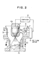
- a fuel injector 4 is supported by a holder 4a disposed centrally of a venturi chamber 4b to cooperate therewith to define an annular venturi 9 which forms a part of the induction passage 2.
- a bypass air passage 7 is formed in the peripheral wall of the venturi chamber 4b and has an upstream end open to a part 8 of the induction passage situated upstream of the venturi 9. The downstream end of the bypass air passage 7 is open to the venturi 9.
- a conventional electric air flow meter 5 is attached to the outer peripheral surface of the venturi chamber 4b and includes a hot-wire type air flow sensor or temperature-sensitive resistor 5a disposed in the bypass air passage 7 to meter the flow of air therethrough and thus to determine the total air flow through the induction passage into an associated engine (not shown).
- the air flow meter 5 produces an electric signal representive of the rate of air flow into the engine and emits the signal to a computor 6 which is operative in response to the input signal to compute the rate of fuel supply optimum to the rate of air supply to the engine for thereby emitting fuel supply signals to the injector 4.
- the injector 4 is responsive to the fuel supply signals from the computor 6 to inject jets of liquid fuel into the induction passage 2 so that the engine is supplied with a mixture of air and fuel at an air/fuel ratio most suited to the engine operation.
- liquid mass When the liquid mass has grown to a certain size, a part of the liquid fuel is separated from the mass to form drops 11 which are then fed into the engine.
- the formation of the liquid mass is quire undesirable to engine idle operations because the addition of the fuel drops 11 to continuous supply of normal air-fuel mixture to the engine is discontinuous and causes a non-uniform rate of fuel supply during an engine idle operation, resulting in an unstable idle operation of the engine, and because the introduction of the liquid fuel drops into the engine increases the CO and HC contents of the engine exhaust gases.
- the improvement of the embodiment of the present invention shown in Figs. 2 and 3 comprises an air passage 12 formed in the peripheral wall of the throttle body 1 and extends in bypassing relationship to the gap 10 defined between the inner peripheral surface of the throttle body 1 and the upward edge portion of the throttle valve 3 when it is in its idle position.
- the bypass air passage 12 has its upstream end 13 open to the induction passage 2 at a point disposed radially outwardly of the cone of the jet of fuel injected by the fuel injector 4.
- the downstream end 15 of the bypass air passage 12 is open to the induction passage 2 at a point downstream of the upstream edge portion of the throttle valve 3 when in its idle position and directed substantially toward the central zone of the undersurface or downstream face of the throttle valve 3.
- bypass air passage 12 When the engine is in its idle operation, a part of the air which has passed through the venturi 9 enters the bypass air passage 12 and flows therethrough in bypassing relationship to the flow of air and fuel particles passing through the gap 10.
- the bypass air is then jetted through the downstream end 15 of the bypass air passage 12 into the induction passage 2 downstream of the throttle valve 3.
- the jet of air is directed substantially toward the central zone of the downstream face of the throttle valve 3 to eliminate or compensate for the difference in pressure between the induction passage 2 just downstream of the throttle valve 3 and the sections of the induction passage 2 adjacent to the gaps 10 which difference would otherwise be caused due to the reason discussed above in'connection with the prior art.
- the upstream end 13 of the bypass air passage 12 is disposed outwardly of the cone of the jet of fuel injected by the injector 4, the air flowing through the bypass air passage 12 and jetted through the downstream end 15 thereof does not contain any amount of fuel.
- the inner peripheral surface of the induction passage 2 downstream of the downstream end 15 of the bypass air passage 12 is prevented from being adhered by any liquid film or drops of the fuel which would oterwise flow through the bypass air passage 12.
- Such a liquid film or drops of fuel cannot easily be atomized and thus will adversely affect the engine operation and emission control.
- the upstream end 13 of the bypass air passage 12 is located downstream of the downstream end 14 of the first bypass air passage 7 which contains the temperature-sensitive air flow sensor element 5a.
- the part of the air flow which passes through the second bypass air passage 12 is included in the total air flow to the engine which has already been measured by the air flow meter 5. This feature is advantageous in the view point of air-fuel ratio control.
- the position of the downstream end 15 of the bypass air passage 12 is important to attain the intended purpose.
- the downstream end 15 is positioned at a level substantially the same as the level of the downstream edge portion of the throttle valve 3 when in its idle position.
- the downstream end 15 of the bypass air passage 12 is located. immediately or slightly below the upstream edge portion of the throttle valve 3 when in the idle position.
- the bypass air passage downstream end 15, however, is not limited to the positions shown in Figs. 2 and 4 and can be located at any point within the distance or range defined between the positions shown in Figs. 2 and 4.
- bypass air passage downstream end 15 should be open in the induction passage 2 on the side thereof substantially aligned with the upstream edge portion of the throttle valve 3 as viewed in the flow of air through the induction passage 2, namely, on the righthand side of the induction passage 2 as viewed on the illustrations in Figs. 2 and 4. If the downstream end 15 of the bypass air passage 12 were formed in the lefthand side of the induction passage 2, i.e., adjacent to the downstream edge portion of the throttle valve 3, the air jetted from such a downstream end will not be operative to prevent the downsteram face of the throttle valve 3 from being adhered by fuel particles.
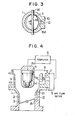
- the downsteam end 15 of the bypass air passage 12 is in the form of a circular opening 15A, as shown in Fig. 3.
- the bypass air passage downstream end 15 is in the form of an arcuate slit or groove 15B formed in the inner peripheral surface of the throttle body 1 and extending circumferentially thereof over a predetermined angle.
- the opposite ends of the length of the groove 15B are shaped to direct air substantially toward the central area of the undersurface or downstream face of the throttle valve 3 when it is in its idle position.
- an air nozzle 17 is fitted into the downstream end of the bypass air passage 12 and extends inwardly from the inner peripheral surface of the throttle body 1 substantially toward the center of the bypass air passage 2.
- the air nozzle 17 is provided with nozzle orifice 17A adjacent to the inner end of the nozzle 17.
- the air entering the bypass air passage 12 is jetted through the nozzle orifice 17A to the central space of the induction passage just downstream of the throttle valve to reliably compensate for the diference in pressure between the central space of the induction passage immediately downstream of the throttle valve 3 and the peripheral zone of the induction passage 2 adjacent to the gaps 10, whereby the whirling-up of the air and fuel particles just downstream of the throttle valve is prevented.
- the nozzle orifice 17A adjacent to the inner end of the air nozzle 17 defines the narrowest section of the bypass air passage 12, so that the air is jetted through the nozzle orifice 17A substantially at sonic velocity.
- the sonic air jet therefore, is operative to atomize the fuel particles in the induction passage just downstream of the throttle valve to thereby improve the stability of the engine idle operation.
- the intake system according to the present invention is effete to prevent the formation of drops of fuel during engine idle operations for thereby ensuring smooth engine idle operations and reduced emissin of CO and HC during engine idle operations.
Landscapes
- Engineering & Computer Science (AREA)
- Chemical & Material Sciences (AREA)
- Combustion & Propulsion (AREA)
- Mechanical Engineering (AREA)
- General Engineering & Computer Science (AREA)
- Control Of Throttle Valves Provided In The Intake System Or In The Exhaust System (AREA)
- Electrical Control Of Air Or Fuel Supplied To Internal-Combustion Engine (AREA)
- Fuel-Injection Apparatus (AREA)
Applications Claiming Priority (2)
| Application Number | Priority Date | Filing Date | Title |
|---|---|---|---|
| JP187043/83 | 1983-10-07 | ||
| JP58187043A JPS6079162A (ja) | 1983-10-07 | 1983-10-07 | 燃料噴射装置 |
Publications (3)
| Publication Number | Publication Date |
|---|---|
| EP0137470A2 true EP0137470A2 (de) | 1985-04-17 |
| EP0137470A3 EP0137470A3 (en) | 1987-04-01 |
| EP0137470B1 EP0137470B1 (de) | 1989-08-02 |
Family
ID=16199171
Family Applications (1)
| Application Number | Title | Priority Date | Filing Date |
|---|---|---|---|
| EP84111962A Expired EP0137470B1 (de) | 1983-10-07 | 1984-10-05 | Einlassanlage für Brennkraftmaschine |
Country Status (6)
| Country | Link |
|---|---|
| US (1) | US4584981A (de) |
| EP (1) | EP0137470B1 (de) |
| JP (1) | JPS6079162A (de) |
| KR (1) | KR920002515B1 (de) |
| CA (1) | CA1221590A (de) |
| DE (1) | DE3479231D1 (de) |
Cited By (4)
| Publication number | Priority date | Publication date | Assignee | Title |
|---|---|---|---|---|
| GB2204358A (en) * | 1987-04-30 | 1988-11-09 | Weber Srl | I.c. engine fuel injector throttle body |
| US4926821A (en) * | 1985-11-02 | 1990-05-22 | Vdo Adolf Schindling Ag | Electronic controller for internal combustion engines |
| GB2303405A (en) * | 1995-07-14 | 1997-02-19 | Nippon Denso Co | I.c. engine throttle valve apparatus with freeze prevention |
| US5704335A (en) * | 1995-07-14 | 1998-01-06 | Nippondenso Co., Ltd. | Throttle valve apparatus for internal combustion engine |
Families Citing this family (8)
| Publication number | Priority date | Publication date | Assignee | Title |
|---|---|---|---|---|
| JPS6296776A (ja) * | 1985-10-23 | 1987-05-06 | Nissan Motor Co Ltd | 内燃機関の燃料供給装置 |
| JPH0612755U (ja) * | 1992-07-21 | 1994-02-18 | 日本電装株式会社 | 内燃機関の混合気供給装置 |
| US5575264A (en) * | 1995-12-22 | 1996-11-19 | Siemens Automotive Corporation | Using EEPROM technology in carrying performance data with a fuel injector |
| US6467465B1 (en) * | 2001-01-10 | 2002-10-22 | Anthony R. Lorts | Throttle body fuel injector adapter manifold |
| AU756938B1 (en) | 2002-04-04 | 2003-01-30 | Hyundai Motor Company | Engine idle speed control device |
| US7007930B1 (en) * | 2003-11-24 | 2006-03-07 | Walbro Engine Management, L.L.C. | Dual fuel feed system carburetor |
| US10082092B2 (en) | 2014-04-03 | 2018-09-25 | Ford Global Technologies, Llc | Method and system for vacuum generation using a throttle |
| US9964080B2 (en) | 2016-08-25 | 2018-05-08 | Ford Global Technologies, Llc | Method and system for vacuum generation using a throttle |
Family Cites Families (11)
| Publication number | Priority date | Publication date | Assignee | Title |
|---|---|---|---|---|
| US2487774A (en) * | 1943-11-17 | 1949-11-08 | Pieter W Schipper | Fuel metering device |
| US3814389A (en) * | 1972-05-02 | 1974-06-04 | P August | Carburetor |
| GB1451100A (en) * | 1973-11-16 | 1976-09-29 | Ford Motor Co | Carburettor idle system |
| JPS55148927A (en) * | 1979-05-09 | 1980-11-19 | Hitachi Ltd | Air-fuel ratio controller |
| JPS55156239A (en) * | 1979-05-24 | 1980-12-05 | Nippon Denso Co Ltd | Air intake device of engine |
| DE3032066A1 (de) * | 1980-08-26 | 1982-04-15 | Robert Bosch Gmbh, 7000 Stuttgart | Gemischbildungsanlage fuer gemischverdichtende fremgezuendete brennkraftmaschinen |
| DE3034996A1 (de) * | 1980-09-17 | 1982-04-29 | Hans Jürgen Bregenz August | Zentraleinspritzung fuer gemischverdichtende brennkraftmaschinen |
| US4359983A (en) * | 1981-04-02 | 1982-11-23 | General Motors Corporation | Engine idle air control valve with position counter reset apparatus |
| DE3141154C2 (de) * | 1981-10-16 | 1993-10-21 | Bosch Gmbh Robert | Kraftstoffeinspritzanlage |
| JPS58152162A (ja) * | 1982-03-04 | 1983-09-09 | Hitachi Ltd | 燃料制御装置 |
| JPS59165862A (ja) * | 1983-03-08 | 1984-09-19 | Automob Antipollut & Saf Res Center | 単点燃料噴射装置 |
-
1983
- 1983-10-07 JP JP58187043A patent/JPS6079162A/ja active Granted
-
1984
- 1984-10-04 KR KR1019840006140A patent/KR920002515B1/ko not_active Expired
- 1984-10-04 CA CA000464734A patent/CA1221590A/en not_active Expired
- 1984-10-05 EP EP84111962A patent/EP0137470B1/de not_active Expired
- 1984-10-05 US US06/658,024 patent/US4584981A/en not_active Expired - Fee Related
- 1984-10-05 DE DE8484111962T patent/DE3479231D1/de not_active Expired
Cited By (7)
| Publication number | Priority date | Publication date | Assignee | Title |
|---|---|---|---|---|
| US4926821A (en) * | 1985-11-02 | 1990-05-22 | Vdo Adolf Schindling Ag | Electronic controller for internal combustion engines |
| GB2204358A (en) * | 1987-04-30 | 1988-11-09 | Weber Srl | I.c. engine fuel injector throttle body |
| US4905651A (en) * | 1987-04-30 | 1990-03-06 | Weber S.R.L. | Device for forming and metering an air and fuel mixture for an internal combustion engine |
| GB2204358B (en) * | 1987-04-30 | 1992-02-19 | Weber Srl | Device for forming and metering an air and fuel mixture for an internal combustion engine |
| GB2303405A (en) * | 1995-07-14 | 1997-02-19 | Nippon Denso Co | I.c. engine throttle valve apparatus with freeze prevention |
| US5704335A (en) * | 1995-07-14 | 1998-01-06 | Nippondenso Co., Ltd. | Throttle valve apparatus for internal combustion engine |
| GB2303405B (en) * | 1995-07-14 | 1999-01-20 | Nippon Denso Co | Intake air controlling apparatus for an internal combustion engine |
Also Published As
| Publication number | Publication date |
|---|---|
| DE3479231D1 (en) | 1989-09-07 |
| JPH0211734B2 (de) | 1990-03-15 |
| CA1221590A (en) | 1987-05-12 |
| US4584981A (en) | 1986-04-29 |
| JPS6079162A (ja) | 1985-05-04 |
| EP0137470A3 (en) | 1987-04-01 |
| KR850003931A (ko) | 1985-06-29 |
| EP0137470B1 (de) | 1989-08-02 |
| KR920002515B1 (ko) | 1992-03-27 |
Similar Documents
| Publication | Publication Date | Title |
|---|---|---|
| US4246874A (en) | Internal combustion engine with dual induction system and with fuel injection system to discharge fuel into primary induction system | |
| JP2659789B2 (ja) | 燃料噴射弁 | |
| US5323966A (en) | Apparatus for injecting a fuel-air mixture | |
| US4903649A (en) | Fuel supply system with pneumatic amplifier | |
| EP0137470A2 (de) | Einlassanlage für Brennkraftmaschine | |
| US4347823A (en) | Throttle body injection apparatus with distribution skirt | |
| US7438047B2 (en) | Multi-cylinder engine | |
| US4387695A (en) | Fuel injection apparatus | |
| US4351304A (en) | Fuel injection valve | |
| EP0098549B1 (de) | Kraftstoffeinspritzeinrichtung | |
| KR880000356B1 (ko) | 공기유량검출장치 | |
| US4211191A (en) | Fuel supplying device for internal combustion engine | |
| CA1076900A (en) | Fuel supply apparatus for internal combustion engines | |
| US4118444A (en) | Variable venturi carburetion system | |
| JP3083556B2 (ja) | 燃料―空気混合物を噴射するための装置 | |
| US4264537A (en) | Variable venturi type carburetor | |
| US4673536A (en) | Fuel admixture device | |
| US4955349A (en) | Device for preparation of a fuel-air mixture for internal combustion engines | |
| US4272460A (en) | Variable venturi type carburetor | |
| US4574760A (en) | Fuel injection throttle body | |
| US4200073A (en) | Electronic throttle body fuel injection system | |
| US4509483A (en) | Fuel injection apparatus and system | |
| WO1985001778A1 (en) | Engine intake manifold | |
| US4119068A (en) | Carburetor for internal combustion engines | |
| US4290405A (en) | Carburetor with sonic fuel atomizer |
Legal Events
| Date | Code | Title | Description |
|---|---|---|---|
| PUAI | Public reference made under article 153(3) epc to a published international application that has entered the european phase |
Free format text: ORIGINAL CODE: 0009012 |
|
| AK | Designated contracting states |
Designated state(s): CH DE FR GB IT LI NL SE |
|
| PUAL | Search report despatched |
Free format text: ORIGINAL CODE: 0009013 |
|
| AK | Designated contracting states |
Kind code of ref document: A3 Designated state(s): CH DE FR GB IT LI NL SE |
|
| 17P | Request for examination filed |
Effective date: 19870403 |
|
| 17Q | First examination report despatched |
Effective date: 19870903 |
|
| GRAA | (expected) grant |
Free format text: ORIGINAL CODE: 0009210 |
|
| AK | Designated contracting states |
Kind code of ref document: B1 Designated state(s): DE FR GB |
|
| REF | Corresponds to: |
Ref document number: 3479231 Country of ref document: DE Date of ref document: 19890907 |
|
| ET | Fr: translation filed | ||
| PLBE | No opposition filed within time limit |
Free format text: ORIGINAL CODE: 0009261 |
|
| STAA | Information on the status of an ep patent application or granted ep patent |
Free format text: STATUS: NO OPPOSITION FILED WITHIN TIME LIMIT |
|
| 26N | No opposition filed | ||
| PGFP | Annual fee paid to national office [announced via postgrant information from national office to epo] |
Ref country code: FR Payment date: 19910918 Year of fee payment: 8 |
|
| PG25 | Lapsed in a contracting state [announced via postgrant information from national office to epo] |
Ref country code: FR Effective date: 19930630 |
|
| REG | Reference to a national code |
Ref country code: FR Ref legal event code: ST |
|
| PGFP | Annual fee paid to national office [announced via postgrant information from national office to epo] |
Ref country code: GB Payment date: 19930924 Year of fee payment: 10 |
|
| PGFP | Annual fee paid to national office [announced via postgrant information from national office to epo] |
Ref country code: DE Payment date: 19931228 Year of fee payment: 10 |
|
| PG25 | Lapsed in a contracting state [announced via postgrant information from national office to epo] |
Ref country code: GB Effective date: 19941005 |
|
| GBPC | Gb: european patent ceased through non-payment of renewal fee |
Effective date: 19941005 |
|
| PG25 | Lapsed in a contracting state [announced via postgrant information from national office to epo] |
Ref country code: DE Effective date: 19950701 |