EP0137472A2 - Dispositif de montage continu de photos - Google Patents
Dispositif de montage continu de photos Download PDFInfo
- Publication number
- EP0137472A2 EP0137472A2 EP84111979A EP84111979A EP0137472A2 EP 0137472 A2 EP0137472 A2 EP 0137472A2 EP 84111979 A EP84111979 A EP 84111979A EP 84111979 A EP84111979 A EP 84111979A EP 0137472 A2 EP0137472 A2 EP 0137472A2
- Authority
- EP
- European Patent Office
- Prior art keywords
- sheet
- sheets
- mount
- band
- continuous photo
- Prior art date
- Legal status (The legal status is an assumption and is not a legal conclusion. Google has not performed a legal analysis and makes no representation as to the accuracy of the status listed.)
- Withdrawn
Links
- 239000002390 adhesive tape Substances 0.000 claims abstract description 11
- 238000001514 detection method Methods 0.000 claims description 8
- 238000003780 insertion Methods 0.000 claims description 4
- 230000037431 insertion Effects 0.000 claims description 4
- 238000009966 trimming Methods 0.000 claims description 2
- 238000007789 sealing Methods 0.000 claims 1
- 239000000463 material Substances 0.000 description 2
- 230000003287 optical effect Effects 0.000 description 2
- 239000000853 adhesive Substances 0.000 description 1
- 230000001070 adhesive effect Effects 0.000 description 1
- 230000005540 biological transmission Effects 0.000 description 1
- 229910003460 diamond Inorganic materials 0.000 description 1
- 239000010432 diamond Substances 0.000 description 1
- 230000000694 effects Effects 0.000 description 1
- 238000000034 method Methods 0.000 description 1
- 239000011347 resin Substances 0.000 description 1
- 229920005989 resin Polymers 0.000 description 1
- 230000000717 retained effect Effects 0.000 description 1
- 239000012780 transparent material Substances 0.000 description 1
Images



Classifications
-
- B—PERFORMING OPERATIONS; TRANSPORTING
- B42—BOOKBINDING; ALBUMS; FILES; SPECIAL PRINTED MATTER
- B42F—SHEETS TEMPORARILY ATTACHED TOGETHER; FILING APPLIANCES; FILE CARDS; INDEXING
- B42F5/00—Sheets and objects temporarily attached together; Means therefor; Albums
Definitions
- This invention relates to a continuous photo mount sheet which can be used not only for observation of photographed objects such as printed pictures in sequential and sorted-out arrangement but also in a video recording system (hereinafter referred to as a video printer) when these pictures are recorded by a video camera on magnetic tapes, magnetic discs, etc.
- a video printer a video recording system
- the continuous photo mount according to this invention is characterized in that plural windows are provided at given intervals on the surface (front) side of a mount sheet body comprising two sheets, i.e.
- the surface side and the rear sids sheets which are attached in manner to form plural pockets having said windows which are open at the upper end so that a frame of film or a printed picture can be inserted therethrough, and that a small hole is perforated on either one of said two sheets in order to retain a printed picture or a film frame inserted in a pocket with a piece of adhesive tape attached on either one of the sheets, the adhesive tape being attached on the surface side if said either one sheet is the surface side sheet, or on the rear side if it is the rear side sheet, and a folding line is provided at the center of the two pockets.
- Fig. 1(a) is a front view of a continuous photo mount according to this invention in the first embodiment and Fig. l(b) a cross sectional view of Fig. 1(a) along the line X-X; wherein a mount sheet body 1 comprises a surface front side, band sheet 2 and a rear side band sheet 3 which have a predescribed width and extend in the longitudinal direction in an endless manner, and windows 4 are provided on the surface side band sheet 2 in the longitudinal direction and at predetermined intervals.
- Pockets 9 for storing a printed picture or a film frame are repeatedly formed in the longitudinal direc- tion of the mount sheet body 1 between the surface side band sheet 2 and the rear side band sheet 3, each having a window on the surface and an opening on the upper end thereof so that a printed picture of a film frame can be inserted therein.
- a pocket 9 is formed and contoured by an adhesive-sealed portion 7 at the center 5 of adjacent windows and the lower end 6 so as to form an opening on the upper end and a window at the center of a pocket. If a printed picture or a frame of film is inserted in the pocket 9, it can be viewed as in an ordinary album, or can be video recorded through the window 4 on a video tape.
- a small elliptic hole 10 is perforated on the rear side band sheet 3 which comprises the pocket 9 substantial ly in the center of the window 4 in this embodiment.
- a piece of adhesive tape 11 is attached on the back of the rear side band sheet 3 in a manner to cover the small hole 10, the printed picture or the frame of film inserted in the pocket 9 can be retained at the correct position and prevented from misplacement or misalignism.
- one hole is providod at the center in this embodiment, it may be in a plural number or may be provided at a position which is not visible through the window 4. It is preferable to provide a hole at a position invisible from the window 4 in the case the object A is transparent, e.g. a reversal film or a negative film.
- the small hole 10 may be perforated outside the window 4. In this case, the adhesive tape 11 is attached on the surface of the surface side band sheet 2.
- the shape, number and position of the small holes 10 are by no means limited to those of this embodiment.
- a positioning mark 13 may be provided at a predetermined position on the mount sheet body 1 to determine the position of the printed picture or the film in respect of the frame or the window 4. This enables correct determination of the relative positions of the print or the film within the window 4 and the video camera.
- the type of positioning mark 13 depends on the detecting method, i.e. whether it is mechanical, magnetic or optical. For example, if an optical detecting system is used, one perforation suffices.
- a folding line 12 is provided at the center of adjacent pockets 9 on the body 1 so that the body 1 can be easily and compactly folded.
- the material of the body 1 may be paper, resin film or any other materials so far as it can function as a photo mount sheet. If a picture of transmission type is to be stored in the pocket 9 and recorded by a video camera, another window may be opened on the rear side band sheet 3 corresponding. to the window on the surface side band sheet 2 Alternatively, the rear side band sheet 3 may be made frcm transparent material.
- the window is shaped rectangular and is formed at an interval from adjacent window, but the dimension and form of the window can be varied arbitrarily to suit a video TV album.
- the shape is not limited to a rectangle.
- the pocket may be made in a size sufficiently larger than the area of a window 4 so that a user can freely move a print or a film within the pocket 9 for trimming. This allows users to freely select the center of images of a picture.
- the pocket 9 for a print or a film is formed on the mount sheet body 1 in the longitudinal direction to have an opening 8 and a window 4.
- a sealed portion 7 may be provided with a piece of adhesive at the center 5 of adjacent windows 4.
- sealed portion is not formed on both sides 5 and the lower end 6 of a pocket 4 but on both sides 5 alone.
- Fig. 2 is a front view of the fourth embodiment of this invention wherein the height of a mount sheet body 1 is determined so as to allow insertion of an elongated object A in a pocket, in order that it would not project from the body 1 to hamper the video recording operation.
- the print will neither project from the body 1 nor hamper video recording.
- Fig. 3 shows the fifth embodiment of this invention in a front view.
- Blank spaces 14 are provided on the upper portion of a body 1 in this embodiment so that the data specified by users can be recorded.
- data includes the time for video recording, refinement of picture quality, the date, name of the photographer, location, whether it has been zoomed or not, positioning of the print in the vertical direction, etc. With such information, users' specification can be directly conveyed when recording.
- the data recording space 14 may be bar codes which are provided in advance and marked for specific codes. It may be machine perforation or simply blank spaces where a user can write or mark freely. If such a recording space 14 is interlocked with A reading device, the data specified by users can be automatically incorporated at the time of video recording.
- the recording space 14 is provided on the surface side band sheet 2 in this embodiment, the position thereof is not limited thereto. Further, the space nay be used not only for users' specification but also for data regarded necessary for the video printer operation.
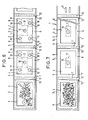
- Fig. 4 is a front view of the sixth embodiment of this invention wherein the surface 3a of a rear side band sheet 3 of the body 1 or the side on which an object A is mounted is colored or patterned in a chromatic or an achromatic color. This is effective in obscuring the boundary between the mount sheet and a print on TV screen when a narrow print or a film frame is inserted in the pocket and blank spaces are left. Applying the sheet with specified color is further effective in improving the color balance of the user's receiver. It is preferable to use blue or black as it blurs the blank spaces on the reproduced picture.
- the reproduced picture can be modified or varied by an intermediate mount sheet (mask) 15 which is optionally inserted in a pocket 9 in a manner described hereinbelow.
- the intermediate mount sheet 15 may be formed in a variety of shapes as shown in Figs. 5(a) through 5(c); i.e. provided with a blank column for filling letters, a heart shape, a diamond shape, etc. Users can enjoy a variety of pictures for video recording simply by selecting a desirable intermediate mount sheet 15.
- Fig. 5(a) there is provided a horizontal column for writing the name of photographer, and the date and place of photographing in a portion of the sheet 15. It is convenient if a machine perforation is provided so as to remove such a column if not needed.
- the continuous photo mount according to this invention can naturally be used without the intermediate mount sheet 15 and any of the small holes 10 may be used for fixing the intermediate mount sheet 15: .
- Fig. 6 is a front view of the eighth embodiment of this invention.
- the rear side band sheet 3 of the pocket 4 is perforated with five small holes 10 one of which is positioned substantial ly in the center of the window 4 and the rest surrounding the center hole from four sides.
- a piece of adhesive tape 11 is attached on the rear surface of the rear side band sheet 3 in a manner to cover those small holes 10, a print or a film, once inserted in a pocket, can be secured at the right position without misplacement or misalignment.
- those small holes 10 provided on the rear side band sheet 3 are perforated exclusively for securing the object A, it is not always necessary to provide them in the number of five, but they may be provided in a plural number at positions invisible from the window 4.
- the holes are preferably provided in a plural number at positions invisible from the window 4.
- the small holes 10 may be provided in a plural number in a frame portion outside the window 4.
- the adhesive tape 11 is attached on the surface of the surface side band sheet 2.
- the shape, number or position of the small holes 10 are by no means limited to the one shown in this embodiment.
- Fig. 7 is a front view of the ninth embodiment of this invention wherein a mark 17 on the terminal end and a small hole 10 are utilised as a terminal end detection mark. More particularly, if a user inserted objects A in all of the pockets 9 of a continuous photo mount sheet and asks for video recording, then all of the small holes 10 are hidden behind the objects A. In this case, a mark 17 provided on the terminal end is used as a terminal end detection mark. However, when a user inserts objects A in one or more pockets 9 of a mount sheet with some pockets unfilled, then tho small holes 10 will be visible through a window 4 from a pocket 9 immediately adjacent to the last pocket 9 which contains the object A.
- the first small hole 10 may be used as the terminal end detection mark.
- the mark 17 provided on the terminal end of the body 1 may be used as the terminal end detection mark instead of the small hole 10.
- the small hole 10 or the mark 17 which appears first is used as the terminal end detection mark. If the small holes 10 are not used as the terminal end detection mark, they may be positioned at places invisible from the window 4.
- Fig. 8 is a front view of the tenth embodiment of this invention wherein a mount sheet body 1 comprises a surface side sheet 2' and a rear side sheet 3' of a predetermined width. Windows 4 are formed on the surface side sheet 2' at predetermined intervals horizontally as well as vertically. Further, the surface side sheet 2 and the rear side sheet 3 are attached to form pockets for encasing a print or a frame of film which have windows respectively and openings on upper portionsthereof in vertical and horizontal directions of the mount sheet body 1.
- the mount carrier of the body 1 is made 4 frames x 3 frames - 12 frames or the size similar to magazines. If the ratio of the vertical dimension a against the horizontal dimension b of a mount sheet body 1 coincidens with the aspect ratio of the reproducing machine (currently a : b - 3 : : 4), the mount sheet body 1 as a whole can be contained within one frame of the reproduced picture. This will facilitate preparing an index of pictures before actually video recording individual objects A. If the frame size of respective windows is made to coincide with the aspect ratio of reproducing machines, it is effective since users can anticipate the reproduced picture.
- FIG. 8 can be made a continuous photo mount sheet by multiplying the unit shown in Fig. 8 in the longitudinal direction.
- an easel movable both in X and Y directions should be required. Except for such an easel, all the description made for the first embodiment is applicable to this embodiment.
- FIG. 9 shows a modified embodiment of the continuous photo mount of this invention in front view.
- a mount sheet body 1 comprises a band sheet 2" which extends endlessly in a longitudinal direction with a predetermined width.
- the band sheet 2" is machine-perforated for forming windows at positions at a predetermined interval.
- the perforation 4' for windows is used when the object A is fixed on the rear side of the band sheet 2".
- a window 4 is defined through which video recording is performed.
- the object A When the object A is fixed on the surface side of the band sheet 2", on the other hand, it should be fixed in alignment with a positioning line 16 provided on the mount sheet body 1. By aligning with this line 16, distortion and/or misplacement of a picture frame can be prevented.
- the band sheet 2" is perforated with elliptical small holes 10 substantial ly in the center of the square defined with perforations 4' and at four positions on the periphery thereof.
- an adhesive tape 11 is attached from surface side of the band sheet 2" to cover the holes, the object A is prevented from misplacement or misalignment.
- the adhesive tape 11 is attached from the rear side of the sheet 2".
- the reference numeral 12 in the figure denotes a folding line and 13 a positioning mark for a film.
- the continuous photo mount according to this invention can achieve the following effects:
Landscapes
- Sheet Holders (AREA)
- Photographic Processing Devices Using Wet Methods (AREA)
Applications Claiming Priority (6)
| Application Number | Priority Date | Filing Date | Title |
|---|---|---|---|
| JP15502583U JPS6062980U (ja) | 1983-10-07 | 1983-10-07 | 連続写真台紙 |
| JP15502883U JPS6062983U (ja) | 1983-10-07 | 1983-10-07 | 連続写真台紙 |
| JP155026/83U | 1983-10-07 | ||
| JP15502683U JPS6062981U (ja) | 1983-10-07 | 1983-10-07 | 連続写真台紙 |
| JP155025/83U | 1983-10-07 | ||
| JP155028/83U | 1983-10-17 |
Publications (2)
| Publication Number | Publication Date |
|---|---|
| EP0137472A2 true EP0137472A2 (fr) | 1985-04-17 |
| EP0137472A3 EP0137472A3 (fr) | 1987-09-30 |
Family
ID=27320758
Family Applications (1)
| Application Number | Title | Priority Date | Filing Date |
|---|---|---|---|
| EP84111979A Withdrawn EP0137472A3 (fr) | 1983-10-07 | 1984-10-05 | Dispositif de montage continu de photos |
Country Status (2)
| Country | Link |
|---|---|
| US (1) | US4601573A (fr) |
| EP (1) | EP0137472A3 (fr) |
Cited By (2)
| Publication number | Priority date | Publication date | Assignee | Title |
|---|---|---|---|---|
| GB2204151A (en) * | 1987-04-10 | 1988-11-02 | P C A Slide Holders Limited | Slide holder |
| GB2362319A (en) * | 2000-05-19 | 2001-11-21 | Denis Wright Ltd | Multiple photoframe card |
Families Citing this family (15)
| Publication number | Priority date | Publication date | Assignee | Title |
|---|---|---|---|---|
| US5083153A (en) * | 1990-08-17 | 1992-01-21 | Eastman Kodak Company | Film transporting apparatus |
| US6301002B1 (en) * | 1993-12-22 | 2001-10-09 | Eastman Kodak Company | Film holder |
| US8261993B2 (en) | 1994-05-25 | 2012-09-11 | Marshall Feature Recognition, Llc | Method and apparatus for accessing electronic data via a familiar printed medium |
| US6866196B1 (en) * | 1994-05-25 | 2005-03-15 | Spencer A. Rathus | Method and apparatus for accessing electronic data via a familiar printed medium |
| US6164534A (en) * | 1996-04-04 | 2000-12-26 | Rathus; Spencer A. | Method and apparatus for accessing electronic data via a familiar printed medium |
| US8910876B2 (en) | 1994-05-25 | 2014-12-16 | Marshall Feature Recognition, Llc | Method and apparatus for accessing electronic data via a familiar printed medium |
| US7703683B2 (en) | 1994-05-25 | 2010-04-27 | Marshall Feature Recognition, Llc | Method and apparatus for accessing electronic data via a familiar printed medium |
| US7712668B2 (en) * | 1994-05-25 | 2010-05-11 | Marshall Feature Recognition, Llc | Method and apparatus for accessing electronic data via a familiar printed medium |
| US7717344B2 (en) * | 1994-05-25 | 2010-05-18 | Marshall Feature Recognition, Llc | Method and apparatus for accessing electronic data via a familiar printed medium |
| US5922458A (en) * | 1995-08-03 | 1999-07-13 | Herlihy; Virginia L. | Display holder easel and work board employing reusable pressure sensitive adhesive |
| EP1088681A3 (fr) * | 1999-09-29 | 2001-10-17 | Johannes Honerkamp | Méthode de l'emballage d'un support d'image |
| FR2874803B1 (fr) * | 2004-09-07 | 2006-12-01 | Laurent Lebailly | Support multi panneaux, pliant, de voyage, pour des photographies |
| GB0525856D0 (en) * | 2005-12-20 | 2006-02-01 | Kaylow Charles W | Fixing apparatus |
| US8964272B2 (en) * | 2006-10-27 | 2015-02-24 | Hewlett-Packard Development Company, L.P. | Transparency template |
| US7610708B2 (en) * | 2007-01-11 | 2009-11-03 | Scholl Margaret C | Chair rail picture frame |
Family Cites Families (10)
| Publication number | Priority date | Publication date | Assignee | Title |
|---|---|---|---|---|
| DE7126017U (de) * | 1971-10-21 | Honerkamp J | Filmtasche | |
| DE7144654U (de) * | 1972-06-15 | Vogt W V Dia Farbfotolaboratorien | Hülle mit aufeinanderfolgenden Taschen zum Aufnehmen von Gegenständen gleicher Art und etwa gleicher Größe,beispielsweise von Diapositiven | |
| GB511235A (en) * | 1937-09-08 | 1939-08-15 | Carl Eggen | An improved wallet for protecting and storing photographic negatives and positives |
| US2687590A (en) * | 1951-10-11 | 1954-08-31 | Johnson & Quin | Film mount |
| CH336357A (de) * | 1955-12-31 | 1959-02-28 | Bolliger Werner | Photoalbum |
| DE1892492U (de) * | 1960-01-18 | 1964-05-06 | Bischof & Klein | Vorrichtung zum aufbewahren von fotos, filmmaterial od. dgl. |
| DE2320940A1 (de) * | 1973-04-25 | 1974-11-07 | High Density Systems Inc | Verfahren zum reproduzieren von bildinformationen enthaltenden blaettern |
| JPS56119153A (en) * | 1980-02-26 | 1981-09-18 | Fuji Xerox Co Ltd | Carrier device for copied original |
| DE3021138C2 (de) * | 1980-06-04 | 1983-07-28 | geb.Böser Liesel 6336 Solms Martin | Diaband |
| US4405228A (en) * | 1981-06-15 | 1983-09-20 | Muscoplat Richard D | Card negative holder and method of manufacture |
-
1984
- 1984-10-05 EP EP84111979A patent/EP0137472A3/fr not_active Withdrawn
- 1984-10-09 US US06/659,181 patent/US4601573A/en not_active Expired - Lifetime
Cited By (3)
| Publication number | Priority date | Publication date | Assignee | Title |
|---|---|---|---|---|
| GB2204151A (en) * | 1987-04-10 | 1988-11-02 | P C A Slide Holders Limited | Slide holder |
| GB2362319A (en) * | 2000-05-19 | 2001-11-21 | Denis Wright Ltd | Multiple photoframe card |
| GB2362319B (en) * | 2000-05-19 | 2003-07-30 | Denis Wright Ltd | Multiple photoframe cards |
Also Published As
| Publication number | Publication date |
|---|---|
| US4601573A (en) | 1986-07-22 |
| EP0137472A3 (fr) | 1987-09-30 |
Similar Documents
| Publication | Publication Date | Title |
|---|---|---|
| EP0137472A2 (fr) | Dispositif de montage continu de photos | |
| US4966285A (en) | Container having index sheet and recording medium | |
| EP0624823B1 (fr) | Page de stockage de film | |
| US6078758A (en) | Printing and decoding 3-D sound data that has been optically recorded onto the film at the time the image is captured | |
| US5437514A (en) | Photographic album leaf | |
| US4704796A (en) | Framer | |
| US4320591A (en) | Flip-type photo album | |
| JP4399125B2 (ja) | 画像表示装置および画像表示方法 | |
| JP3005716B1 (ja) | 写真シール払出装置 | |
| JPH0213181Y2 (fr) | ||
| JPH09211835A (ja) | インデックスプリント及び再プリント注文シート | |
| JP2648645B2 (ja) | 写真集の作製方法及び注文票 | |
| JPS63458Y2 (fr) | ||
| JPH0355979Y2 (fr) | ||
| JP3040187U (ja) | カセット収納用ケースにおけるインデックスカード | |
| JPH08320660A (ja) | カードケース | |
| JP2925844B2 (ja) | 現像済み写真フイルムの収納容器 | |
| JPH09116857A (ja) | 画像表示媒体、及びその作製方法 | |
| JPS6321191A (ja) | アルバム | |
| JPH07108792A (ja) | 写真の整理方法と集合写真および写真を並べる道具 | |
| JPH068982B2 (ja) | 画像記録媒体収納方法及び容器及びピクチャーカード | |
| JPS59100424A (ja) | 写真プリント | |
| JP4502175B2 (ja) | 写真用フィルムの収納体 | |
| GB2137879A (en) | A picture frame assembly and method of using same | |
| JPH0213182Y2 (fr) |
Legal Events
| Date | Code | Title | Description |
|---|---|---|---|
| PUAI | Public reference made under article 153(3) epc to a published international application that has entered the european phase |
Free format text: ORIGINAL CODE: 0009012 |
|
| AK | Designated contracting states |
Designated state(s): DE FR GB NL |
|
| PUAL | Search report despatched |
Free format text: ORIGINAL CODE: 0009013 |
|
| AK | Designated contracting states |
Kind code of ref document: A3 Designated state(s): DE FR GB NL |
|
| 17P | Request for examination filed |
Effective date: 19880318 |
|
| 17Q | First examination report despatched |
Effective date: 19890908 |
|
| STAA | Information on the status of an ep patent application or granted ep patent |
Free format text: STATUS: THE APPLICATION IS DEEMED TO BE WITHDRAWN |
|
| 18D | Application deemed to be withdrawn |
Effective date: 19900119 |
|
| RIN1 | Information on inventor provided before grant (corrected) |
Inventor name: UTSUGI, MIKIOC/O FUJI PHOTO FILM CO., LTD. |