EP0137606A2 - Tank zum Mischen und Aufbewahren von sterilen Suspensionen und Lösungen - Google Patents
Tank zum Mischen und Aufbewahren von sterilen Suspensionen und Lösungen Download PDFInfo
- Publication number
- EP0137606A2 EP0137606A2 EP84305154A EP84305154A EP0137606A2 EP 0137606 A2 EP0137606 A2 EP 0137606A2 EP 84305154 A EP84305154 A EP 84305154A EP 84305154 A EP84305154 A EP 84305154A EP 0137606 A2 EP0137606 A2 EP 0137606A2
- Authority
- EP
- European Patent Office
- Prior art keywords
- container
- recirculation loop
- mixture
- mixer head
- external recirculation
- Prior art date
- Legal status (The legal status is an assumption and is not a legal conclusion. Google has not performed a legal analysis and makes no representation as to the accuracy of the status listed.)
- Withdrawn
Links
- 238000002156 mixing Methods 0.000 title claims abstract description 36
- 239000000725 suspension Substances 0.000 title claims abstract description 26
- 239000000203 mixture Substances 0.000 claims abstract description 39
- 239000000463 material Substances 0.000 claims abstract description 34
- 239000000839 emulsion Substances 0.000 claims abstract description 23
- 239000000243 solution Substances 0.000 claims abstract description 23
- 239000012530 fluid Substances 0.000 claims abstract description 6
- 230000006835 compression Effects 0.000 claims description 5
- 238000007906 compression Methods 0.000 claims description 5
- 238000007789 sealing Methods 0.000 claims description 5
- 239000007971 pharmaceutical suspension Substances 0.000 description 9
- 239000007788 liquid Substances 0.000 description 8
- 238000002360 preparation method Methods 0.000 description 8
- 239000007858 starting material Substances 0.000 description 8
- 239000008251 pharmaceutical emulsion Substances 0.000 description 7
- 239000000047 product Substances 0.000 description 7
- 230000008878 coupling Effects 0.000 description 5
- 238000010168 coupling process Methods 0.000 description 5
- 238000005859 coupling reaction Methods 0.000 description 5
- 238000005187 foaming Methods 0.000 description 5
- 239000000654 additive Substances 0.000 description 4
- 230000000996 additive effect Effects 0.000 description 4
- 239000000084 colloidal system Substances 0.000 description 4
- 230000001804 emulsifying effect Effects 0.000 description 3
- 239000003186 pharmaceutical solution Substances 0.000 description 3
- 238000013019 agitation Methods 0.000 description 2
- 239000006185 dispersion Substances 0.000 description 2
- 239000006260 foam Substances 0.000 description 2
- 238000000265 homogenisation Methods 0.000 description 2
- 238000004806 packaging method and process Methods 0.000 description 2
- 239000007787 solid Substances 0.000 description 2
- 238000003756 stirring Methods 0.000 description 2
- 230000015572 biosynthetic process Effects 0.000 description 1
- 239000003638 chemical reducing agent Substances 0.000 description 1
- 238000010276 construction Methods 0.000 description 1
- 239000003814 drug Substances 0.000 description 1
- 230000000694 effects Effects 0.000 description 1
- 239000012467 final product Substances 0.000 description 1
- 239000010419 fine particle Substances 0.000 description 1
- 229920002457 flexible plastic Polymers 0.000 description 1
- 239000004615 ingredient Substances 0.000 description 1
- 238000000034 method Methods 0.000 description 1
- 238000012986 modification Methods 0.000 description 1
- 230000004048 modification Effects 0.000 description 1
- 235000014366 other mixer Nutrition 0.000 description 1
- 239000002245 particle Substances 0.000 description 1
- 239000012071 phase Substances 0.000 description 1
- 239000000843 powder Substances 0.000 description 1
- 239000011541 reaction mixture Substances 0.000 description 1
- 230000008707 rearrangement Effects 0.000 description 1
- 230000000717 retained effect Effects 0.000 description 1
- 239000007790 solid phase Substances 0.000 description 1
- 239000002904 solvent Substances 0.000 description 1
- 229910001220 stainless steel Inorganic materials 0.000 description 1
- 239000010935 stainless steel Substances 0.000 description 1
- 238000003466 welding Methods 0.000 description 1
Images


Classifications
-
- B—PERFORMING OPERATIONS; TRANSPORTING
- B01—PHYSICAL OR CHEMICAL PROCESSES OR APPARATUS IN GENERAL
- B01F—MIXING, e.g. DISSOLVING, EMULSIFYING OR DISPERSING
- B01F25/00—Flow mixers; Mixers for falling materials, e.g. solid particles
- B01F25/60—Pump mixers, i.e. mixing within a pump
Definitions
- This invention relates to an apparatus for the preparation of a suspension, emulsion or solution, for example, a sterile suspension of fine particles of a pharmaceutical substance in a liquid vehicle.
- the apparatus of the invention is particularly adapted for preparing pharmaceutical suspensions and emulsions in which the disperse phase is of extremely small size.
- the apparatus is simple in structure so that it can be readily sterilized.
- Colloid mills are typically employed as external homogenizing or emulsifying units, although a wide variety of other mixers and grinders have also been employed for this purpose. Colloid mills break up agglomerates of solid particles or subdivide droplets of a dispersed liquid, by means of high speed fluid shear.
- a typical colloid mill employs a rotor which rotates rapidly within and close to the surface of a stator. The materials to be formed into a fine dispersion are fed between the rotor and the stator and thereby are subjected to intense shear and centrifugal force whereby the dispersion is formed. Colloid mills are complex in structure and they are not easy to sterilize. Moreover, they generate a considerable amount of heat during operation, which makes it troublesome to use them to form compositions containing heat- sensitive materials.
- mixers with various mixer head designs are known and are in common use.
- One known type of mixer employs, as a mixing head, a rotatable tubular member having radial slots in the side wall thereof.
- the fluid to be homogenized is drawn axially into the interior of the rotating tubular head and then is expelled radially outwardly through the slots by centrifugal force, whereby the starting materials are intensively mixed.
- Fins or blades are often disposed within the tubular mixer head to enhance the mixing action.
- a mixer head is disposed inside a casing and is rotated by a drive shaft which is driven by a motor located outside of the casing.
- a mechanical seal around the drive shaft to prevent leakage of the material being mixed.
- a further problem with devices for the preparation of pharmaceutical suspensions and emulsions stems from the need periodically to sterilize' the entire interior of the apparatus. It is preferred to sterilize a mixing apparatus by exposing it to steam under pressure for a suitable period of time. If the mixing apparatus, however, is of complex internal structure, it may not be possible to readily sterilize it, as is, by steam under pressure. Thus, additional time and expense will be required to sterilize such a complex mixing apparatus, which is undesirable.
- the present invention includes a mixing apparatus for forming a suspension, emulsion or solution, which apparatus is capable of producing a very homogenous product without causing excessive foaming in the main mixing tank.
- the invention also includes a mixing apparatus, as aforesaid, in which a mixture of materials to be formed into a suspension, emulsion or solution is withdrawn from the bottom of a main mixing tank and is flowed through an external recirculation loop wherein the mixture is subjected to high shear forces effective to form the withdrawn materials into the desired suspension, emulsion or solution, and then the suspension, emulsion or solution is returned to the main tank.
- a mixing apparatus as aforesaid, in which a mixture of materials to be formed into a suspension, emulsion or solution is withdrawn from the bottom of a main mixing tank and is flowed through an external recirculation loop wherein the mixture is subjected to high shear forces effective to form the withdrawn materials into the desired suspension, emulsion or solution, and then the suspension, emulsion or solution is returned to the main tank.
- the invention also includes mixing apparatus for the preparation of suspensions, emulsions and solutions, as aforesaid, which includes an improved shaft seal for preventing leakage of the solution, emulsion or suspension around the drive shaft used to rotate the mixer head.
- the present invention provides a mixing apparatus for preparing suspensions, emulsions or solutions from a mixture of (1) a liquid carrier or vehicle material and (2) one or a mixture of two or more solid or liquid additive materials.
- the starting materials are blended in a closed tank.
- Successive portions of the mixture are continuously withdrawn and recirculated through an external recirculation loop connected to the tank, which loop contains a high-speed, high-shear mixer.
- This mixer is preferably located substantially completely in a recess which adjoins and communicates with the remainder of the external recirculation loop.
- the mixture of the starting materials is drawn into the external recirculation loop from a withdrawal location near to the bottom of the tank and the resulting homogenized suspension, emulsion or solution is returned to a return location also near to the bottom of the tank, but above the withdrawal location at which the mixture is drawn into the external recirculation loop.
- the mixing apparatus of the present invention converts the entirety of the starting mixture into a homogeneous suspension, emulsion or solution.
- the apparatus of the invention is particularly well adapted for forming sterile pharmaceutical suspensions in which the solid phase consists of extremely fine powder material.
- the high-speed, high-shear mixer head is located within a recess or dead-end branch of an otherwise continuous, single conduit forming the external recirculation loop.
- the mixer head is located within one leg of a substantially T-shaped fitting or conduit forming part of the external recirculation loop.
- the T-shaped fitting preferably has a pair of leg or cross-bar portions which are disposed substantially coaxial with and communicating with each other and which jointly define the cross-bar of the T.
- the T-shaped fitting also comprises a stem portion extending from the juncture of the two leg portions at an angle, preferably an angle of 90°, to the common axis of the two leg portions.
- the mixer head is a rotatable tubular member having a plurality of circumferentially spaced apart, radial slots in the side wall thereof.
- the tubular member is mounted in one of said two leg portions of said T-shaped fitting and is rotatable about the common axis of said leg portions.
- the mixture is drawn from the tank into the other leg portion of the T-shaped fitting of the external recirculation loop and then flows into the one leg in which the mixer.head is disposed.
- the mixture then flows axially into the center of the mixer head at the inner end thereof and then flows radially outwardly through the slots in the mixer head, thereby subjecting the mixture to high-intensity shear whereby to homogenize and dissolve, emulsify or disperse the additive material in the liquid vehicle.
- the thus-formed suspension, emulsion or solution then leaves the region surrounding the mixer head in the form of an annular stream which flows in the reverse axial direction, relative to the axial flow of the incoming mixture.
- the annular stream flows countercurrent to and substantially surrounds the centrally located, axial flow of the incoming mixture, and then flows as a unitary stream into the stem portion of the T-shaped fitting.
- the homogenized mixture then is returned to the tank via the return portion of the external recirculation loop.
- the drive shaft used to rapidly rotate the mixer head is sealed by a plurality of annular flexible lip seals alternately stacked with a plurality of elastomeric 0-rings and secured in a seal housing to prevent leakage of fluid from the mixer head around the drive shaft.
- the apparatus 11 includes a mixing tank 12 which is mounted by means of legs 13 on a movable base 14 provided with wheels 16.
- the tank 12 is preferably made of electropolished stainless steel and has a capacity of several hundred liters, for example, 200 liters.
- the mixing tank 12 is provided with a central hatch 17 on the upper side thereof.
- An inlet 18 is formed in the hatch 17 for addition of additive materials into the tank 12.
- a second inlet 19 is provided in the hatch 17 for addition of a liquid vehicle into the tank 12.
- a steam inlet 21 is provided in the hatch 17 for the introduction of live, pressurized steam when it is desired or required to sterilize the interior of the mixing tank 12 and the parts associated therewith.
- An agitation apparatus 22 including a motor 23, a speed reducer 24, a drive shaft 26, and a turbine blade agitator head 27, is disposed centrally with respect to the tank so that the shaft 26 extends into the tank through the top of the hatch 17.
- the motor has a variable speed control which controls the speed of rotation of the shaft 26 so that the turbine blade agitator head 27 stirs the contents of the tank 12 at an appropriate, relatively low speed.
- Such relatively gentle stirring is effective to blend the ingredients without causing substantial foaming, but is normally not sufficiently intensive to form a fine homogeneous suspension or emulsion.
- the materials to be homogenized are added to the tank 12 in a quantity sufficient to fill the tank to a level above the return tube 34 so air will not be added by the high intensity mixer.
- the agitator head 27 can be of any suitable conventional design effective for blending the starting materials and maintaining materials suspended during filling operations.
- the external recirculation loop 31 comprises a first conduit or pipe 32 which communicates with the tank 12 near to or at the bottom thereof, a T-shaped fitting or conduit 33 having a bottom leg 33a which communicates with the conduit 32, a top leg 33b and a stem portion 33c.
- the stem portion 33c is connected to a return conduit or pipe 34 which communicates with the tank 12 near to the bottom thereof, but at a location substantially above the location at which the conduit 32 communicates with the tank 12.
- both conduits 32 and 34 communicate with the tank 12 at the vertically lowermost quarter 12a of the tank.
- a high-speed, high-shear mixer 36 comprises a rotatable mixer head 37 disposed within the upper leg 33b of the T-shaped conduit 33, a drive assembly 38 functionally connected to the mixer head 37 for effecting high-speed rotation thereof, a motor 39 for driving the drive assembly 38, and a control unit 41 for controlling operation of the mixer 36.
- the control unit 41 is conveniently mounted by means of a fixture 46 on the external recirculation loop 31.
- the two flows 54 and 56 are not completely isolated from each other in the zone immediately below the inlet opening 51 of the mixing head. Thus, some mixing of the two streams is possible at the interface between them.
- the apparatus is effective over a period of time to treat all of the contents of the tank to obtain a homogeneous suspension, emulsion or solution.
- the product suspension, emulsion or solution is withdrawn through a product outlet 42 formed on the bottom of the tank 12, travels through a product conduit 43 and is withdrawn from an outlet 44 which is located to the side of the tank 12.
- the product can be removed from the outlet 44 by means of suction, and can be optionally filtered through a filter screen after leaving the outlet 44 prior to packaging.
- a 100 mesh filter screen is typically used for this purpose.
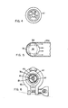
- the details of the structure of the mixer head 37 are shown in Figures 3 and 4.
- the mixer head 37 comprises a central sleeve or hub 57 which defines a cylindrical bore 58.
- the middle portion of the hollow mixer head 37 comprises a central cylinder 59 which defines the side wall of the mixer head, is concentric with the bore 58 and has a plurality of circumferentially spaced-apart, axially elongated, thin openings therein which form the radial outlet slots 52.
- the outlet slots 52 can increase in length in the radially outward direction, as indicated by broken lines in Figure 3.
- the central cylinder 59 is coaxially centered on the central hub 57 by a pair of imperforate, upper and lower, end cones or frusto-conical members 61 and 62, respectively.
- the end cones 61 and 62 decrease in diameter in the axially outward direction relative to the center of the mixer head.
- the end cones 61 and 62 interlock with the central cylinder 59 at upper and lower interlocking portions 63 and 64, respectively.
- the interlocking portions 63 and 64 each comprise a pair of oppositely axially extending, overlapping, annular flanges 66, 67 and 68, 69, wherein the interior flanges 67 and 68 of the pairs are formed on the end cones 61 and 62, respectively.
- a plurality of fins 71 extend radially from the central hub 57 to each of the end cones 61 and 62.
- the fins 71 are secured, as by welding, to the central hub 57 and to the end cones 61 and 62.
- the fins 71 are generally made of relatively thin stock, for example, a sheet about 0.09 inches thick.
- the fins 71 taper outwardly at the axially outward ends thereof 74.
- two fins 71 are associated with each of the end cones 61 and 62. When two fins are used at each end, the fins are spaced apart at intervals of 180°, as shown in Figure 4.
- the lower portion of the drive shaft 76 extends tt-rough the bore 58.
- a nut 77 or other suitable fastening means, is secured at the lower end of the drive shaft 76 and engages the bottom of the mixer head 37.
- the upper end of the mixer head 37 abuts against a top plate 78 which in turn abuts against a radially enlarged shoulder 76a of the drive shaft 76 above the mixer head 37.
- the mixer head 37 is thus rigidly secured between the top plate 78, and the nut 77, and the mixer head 37 thereby rotates integrally with the drive shaft 76.
- the top plate 78 seals the top of the mixer head 37 and provides positive pressure on the shaft seal described hereinafter.
- the nut 77 in the embodiment shown, contacts the lower end of the central hub 57.
- the mixer 36 is effective to create the desired flow of the material in the external recirculation loop 31 without the need for a separate circulating pump. Foaming is minimized in the mixing tank 12 because the conduit 34 returns the intensively mixed materials to the tank beneath the upper surface of the materials therein, so that foam does not tend to form on top of the materials in the tank. Moreover, the. system is substantially closed so that the amount of air that becomes entrained in the material is minimal.
- the structure of the external recirculation loop 31, including the mixer head 37, makes it possible more easily to clean and sterilize the apparatus. All of the materials contained in the tank 12 and the external recirculation loop 31 can be drained through the outlet 42. Steam can readily be flowed through the interior of the tank 12 and the loop 31 because of the relatively open internal structure thereof.
- the drive shaft 76 used to rotate the mixer head 37 at high speeds extends upwardly out of the external recirculation loop 31 and is drivingly connected to the motor 39.
- a closure assembly 81 closes the open end 82 of the top leg 33b of the T-shaped conduit 33 and prevents escape of the materials along the drive shaft 76.
- the closure assembly 81 includes a seal housing or casing 83 which is connected by a flanged coupling 84 to the upper end of the top leg 33b.of the T-shaped conduit 33.
- An annular plate 86 is positioned over the open end 82 of the top leg 33b and is interposed between the seal housing 83 and the top leg 33b.
- a pair of lower and upper elastomeric O-rings or gaskets 87 and 88, respectively, are positioned within a pair of upper and lower annular cavities in the flanged coupling 84 coaxial with the top leg 33b whereby to sealingly engage the annular plate 86 and prevent leakage of the material being mixed therealong.
- Any suitable means can be used to secure together parts of the flanged coupling 84.
- a hinged clamping ring 90 is provided for this purpose.
- the gaskets 87 and 88 can be TRI-CLOVER gaskets and the hinged clamp 90 can be a TRI-CLAMP clamp.
- the drive shaft 76 extends upwardly through the central opening in the plate 86 and thence through an . axial bore 91 in the seal housing 83.
- An annular ring 89 is disposed in the upper portion of the bore 91 and is retained therein by a retainer ring 95.
- the radially inner wall of the ring 89 is radially outwardly spaced from the shaft 76.
- a series of pairs of inner and outer elastomeric 0-rings 92 and 93, respectively, and a plurality of flexible lip seals 94, are disposed in the bore 91 coaxial with the bore 91 and the shaft 76.
- Each of the lip seals 94 comprises an annular disk having a central opening which is slightly smaller in diameter than the diameter of the enlarged portion 76b of the drive shaft.
- each lip seal 94 is smoothly downwardly curved and the radially inner edge thereof touches the surface of the shaft portion 76b.
- the flat, radially outer portion of each lip seal 94 sealingly engages the two associated O-rings 92 and 93 therebelow.
- the upper face of the radially outer portion of each lip seal 94 similarly sealingly engages the O-rings of the adjacent upper pair, except for the uppermost lip seal 94.
- the upper face of the uppermost lip seal 94 is engaged by an annular compression member 96.
- a plurality of T-shaped screws 97 here three screws as shown in Figure 6, are threadedly secured in the ring 89 and the inner ends thereof abut against the upper surface of the compression member 96.
- the lip seals 94 and the pairs of O-rings 92, 93 act to minimize leakage in the following manner. Since the lip seals 94 are of slightly smaller diameter than the upper portion 76b of the drive shaft 76, each seal 94 is bent slightly axially inwardly when the drive shaft 76 is inserted therethrough from the upper end of the housing 83. The lip seals 94 thus assume the slightly bent conformation shown in Figure 2, and thereby come into substantial sealing contact with the drive shaft 76 at the upper portion 76b thereof.
- each lip seal 94 be bent downwardly (axially inwardly) as shown in Figure 2 so that any fluid tending to flow upwardly along the shaft portion 76b will be scraped off by the radially inner edges of the lip seals.
- the O-rings 92, 93 prevent leakage in the radial direction of the seal.
- the O-rings 92, 93 are resiliently deformed into sealing contact with the adjacent surfaces of the lip seals whereby to prevent materials located radially inwardly thereof from passing toward the radially outermost portions of the enlarged bore portion 91.
- the number of lip seals and pairs of 0-rings used can be readily varied according to need.
- the lip seals 94 can be made of a flexible plastic sheet-form material.
- the drive shaft 76 is coupled by means of a sleeve coupling 98 to a motor shaft 99 which is driven by the motor 39.
- the motor 39, shaft 99, sleeve coupling 98, and drive shaft 76 together form the previously mentioned drive shaft assembly 38.
- a batch of the liquid and the additive materials will be placed in the tank 12 and the agitator 27 will be rotated until the batch has been blended to the desired degree. Then the high-speed, high-shear mixer will be run to effect homogenization as described above.
- the agitator 22 and the high-speed, high-shear external mixer 36 are usually run simultaneously during the homogenization portion of the operation.
- the turbine blade agitator head 27 blends the materials in the mixing tank 12 with the homogenized mixture that is returned from the external recirculation loop 31 so that, over a period of time, substantially all of the original contents of the tank 12 will be flowed through and homogenized in the external recirculation loop 31.
- the tank 12 and external recirculation loop 31 can then, if necessary, be cleaned and sterilized by the introduction of pressurized steam through the steam inlet 21. If necessary, the mixer head can be more thoroughly cleaned at this time by removing the closure assembly 81 and withdrawing the mixer head 37 from the top leg 33b of the T-shaped conduit 33.
- the fitting or conduit 33 used in the present invention to contain the external mixer 36 can be of various shapes. Even when the fitting is not substantially T-shaped, the stem portion 33c must be disposed at an angle relative to the top and bottom leg portions 33b and 33a respectively sufficient to create the annular flow depicted in Figure 5. For example, a substantially Y-shaped fitting wherein the portion 33c is disposed at a 45° angle relative to the axis of the portions 33a, 33b could be used in place of the T-shaped fitting 33.
Landscapes
- Chemical & Material Sciences (AREA)
- Chemical Kinetics & Catalysis (AREA)
- Mixers Of The Rotary Stirring Type (AREA)
Applications Claiming Priority (4)
| Application Number | Priority Date | Filing Date | Title |
|---|---|---|---|
| US52243483A | 1983-08-11 | 1983-08-11 | |
| US06/583,781 US4515482A (en) | 1983-08-11 | 1984-02-28 | Sterile suspension and solution holding and mixing tank |
| US522434 | 1995-08-31 | ||
| US583781 | 1996-01-11 |
Publications (2)
| Publication Number | Publication Date |
|---|---|
| EP0137606A2 true EP0137606A2 (de) | 1985-04-17 |
| EP0137606A3 EP0137606A3 (de) | 1987-08-12 |
Family
ID=27060815
Family Applications (1)
| Application Number | Title | Priority Date | Filing Date |
|---|---|---|---|
| EP84305154A Withdrawn EP0137606A3 (de) | 1983-08-11 | 1984-07-30 | Tank zum Mischen und Aufbewahren von sterilen Suspensionen und Lösungen |
Country Status (2)
| Country | Link |
|---|---|
| US (1) | US4515482A (de) |
| EP (1) | EP0137606A3 (de) |
Families Citing this family (17)
| Publication number | Priority date | Publication date | Assignee | Title |
|---|---|---|---|---|
| US4919540A (en) * | 1988-05-27 | 1990-04-24 | Halliburton Company | Self-leveling mixer apparatus |
| JPH07114809B2 (ja) * | 1990-07-30 | 1995-12-13 | 日機装株式会社 | 透析液調整用剤の溶解装置 |
| US5407271A (en) * | 1993-10-07 | 1995-04-18 | Jorgen Jorgensen Maskinfabrik A/S | Integrated rotary mixer and disperser head |
| US5590960A (en) * | 1993-11-04 | 1997-01-07 | E. I. Du Pont De Nemours And Company | One tank paint makeup process using a recirculation loop with liquid injection |
| US6981794B2 (en) * | 2002-04-12 | 2006-01-03 | Hynetics Llc | Methods for mixing solutions |
| US6923567B2 (en) * | 2002-04-12 | 2005-08-02 | Hynetics Llc | Mixing tank assembly |
| US6908223B2 (en) * | 2002-04-12 | 2005-06-21 | Hynetics Llc | Systems for mixing liquid solutions and methods of manufacture |
| RU2314857C2 (ru) * | 2004-12-15 | 2008-01-20 | Федор Иванович Лобанов | Способ обработки суспензии |
| DE102005007175A1 (de) * | 2005-02-16 | 2006-08-17 | Knape, Sandra | Vorrichtung und Verfahren zum Homogenisieren |
| SE534766C2 (sv) * | 2010-04-26 | 2011-12-13 | Itt Mfg Enterprises Inc | Genomföring för rötkammare |
| PT3016736T (pt) * | 2013-07-03 | 2018-11-26 | Admix Inc | Misturador rotativo integrado e cabeça dispersora |
| US9682494B2 (en) * | 2014-03-20 | 2017-06-20 | Amix Systems Ltd. | Colloidal mixing method for slurries |
| FR3036974B1 (fr) * | 2015-06-04 | 2019-09-13 | Technip France | Installation de melange-separation de liquides non miscibles |
| US10960365B2 (en) * | 2016-05-24 | 2021-03-30 | Nissin Giken Co., Ltd. | Apparatus and method for producing fine air bubble mixed liquid |
| US10029222B2 (en) * | 2016-06-23 | 2018-07-24 | Dajustco Ip Holdings Inc. | Agitator having shrouded vanes for submersible pumps |
| CN113262699B (zh) * | 2021-04-16 | 2024-07-23 | 深圳市贝加电子材料有限公司 | 用于咪唑类化合物有机可焊保护剂的制备装置及使用方法 |
| CN118253238B (zh) * | 2024-05-30 | 2024-09-27 | 启东市神华润滑液压设备科技有限公司 | 一种稀有油气混合装置 |
Family Cites Families (52)
| Publication number | Priority date | Publication date | Assignee | Title |
|---|---|---|---|---|
| CA652360A (en) * | 1962-11-13 | Ellegast Konrad | Continuous mixer | |
| DE483569C (de) * | 1929-10-02 | Robert Ersbak | Mischvorrichtung fuer Fluessigkeiten | |
| US1079481A (en) * | 1912-12-07 | 1913-11-25 | Edwin Euston | Process of producing white lead. |
| US1445427A (en) * | 1922-02-11 | 1923-02-13 | Ernest E Werner | Method of producing emulsions |
| US1884664A (en) * | 1922-06-19 | 1932-10-25 | Flintkote Co | Process of making emulsions |
| US1789897A (en) * | 1922-06-19 | 1931-01-20 | Flintkote Co | Apparatus for making emulsions |
| US1722433A (en) * | 1924-03-27 | 1929-07-30 | Kirschbraun Lester | Apparatus for making emulsions |
| US1588901A (en) * | 1925-01-03 | 1926-06-15 | Merrellsoule Company | Mixer |
| US1789320A (en) * | 1925-12-07 | 1931-01-20 | Flintkote Co | Apparatus for mixing materials |
| US1781435A (en) * | 1928-07-06 | 1930-11-11 | Joseph B Carper | Process for the production of paints |
| US1782370A (en) * | 1929-08-17 | 1930-11-18 | Viscose Co | Apparatus for preparing viscous mixtures |
| GB365420A (en) * | 1931-04-07 | 1932-01-21 | Aleksander Furowicz | Improvements in centrifugal mixing devices |
| US2086539A (en) * | 1934-07-24 | 1937-07-13 | Bethune Gaston S P De | Method of and apparatus for producing pastes of food and similar products |
| US2126911A (en) * | 1936-01-06 | 1938-08-16 | George W Mullen | Method and apparatus for dispersing pectin and the like |
| US2146566A (en) * | 1936-05-05 | 1939-02-07 | Mining Process & Patent Co | Apparatus for conditioning and agitating pulps |
| US2148608A (en) * | 1936-11-20 | 1939-02-28 | Stubner Emile C De | Dispersion apparatus |
| US2137328A (en) * | 1937-08-18 | 1938-11-22 | Mixing Equipment Co Inc | Material agitating means |
| GB523340A (en) * | 1938-12-31 | 1940-07-11 | Bohumil Jirotka | An improved method of and device for producing mud for mud-baths or the like |
| US2390898A (en) * | 1943-10-06 | 1945-12-11 | Day J H Co | Turbodissolver |
| US2482235A (en) * | 1946-07-13 | 1949-09-20 | Becchia Hugo | Centrifugal homogenizer |
| US2586781A (en) * | 1948-10-11 | 1952-02-26 | Phillips Petroleum Co | Line fault detector |
| GB677787A (en) * | 1949-08-17 | 1952-08-20 | Millspaugh Ltd | Improvements in or relating to machines for breaking and mixing paper-making materials |
| US2635860A (en) * | 1951-06-11 | 1953-04-21 | Premier Mill Corp | Centrifugal mixing device |
| DE872928C (de) * | 1951-09-08 | 1953-04-09 | J K August Lahmann | Vorrichtung zum Umschichten, Auflockern und/oder Mischen von Mehl und sonstigem Schuettgut in Silos u. dgl. Vorratsbehaeltern mittels eines in das Gut hineinversenkten Blasrohr-Systems |
| GB722462A (en) * | 1952-08-08 | 1955-01-26 | Trist & Co Ltd Ronald | Improvements in packings between relatively reciprocating or rotating members |
| US2718385A (en) * | 1952-12-23 | 1955-09-20 | Ethyl Corp | Stirring apparatus |
| US2791407A (en) * | 1954-07-07 | 1957-05-07 | Jack Danciger | Water agitating circulator |
| US2769623A (en) * | 1955-03-08 | 1956-11-06 | Patterson Foundry & Machine Co | Turbine mixer |
| US2985389A (en) * | 1955-09-02 | 1961-05-23 | Willems Peter | Apparatus for physical and/or chemical treatment of materials |
| DE1190439B (de) * | 1957-04-25 | 1965-04-08 | Wolfen Filmfab Veb | Vorrichtung zum Loesen, Mischen, Emulgieren, Homogenisieren u. dgl. von Stoffgemischen, die schwerloesliche feste und fluessige Anteile enthalten |
| US2997373A (en) * | 1959-01-19 | 1961-08-22 | Barnard & Leas Mfg Company Inc | Dissolving apparatus |
| US3081981A (en) * | 1959-02-17 | 1963-03-19 | Eastman Kodak Co | Centrifugal pump system |
| US3192942A (en) * | 1961-08-15 | 1965-07-06 | Rockwell Mfg Co | Plug valve assembly |
| US3184221A (en) * | 1962-01-23 | 1965-05-18 | Liberty Nat Bank And Trust Com | Homogenizing apparatus |
| DE1294121B (de) * | 1962-06-28 | 1969-04-30 | Chemical Construction Corp | Stopfbuchsdichtung |
| US3112634A (en) * | 1962-07-02 | 1963-12-03 | Sandy Hill Iron & Brass Works | Mixing tank |
| US3169776A (en) * | 1963-03-18 | 1965-02-16 | Packing Supply Company | Multiple purpose self-loading machinery packing |
| US3170638A (en) * | 1963-04-12 | 1965-02-23 | Linwood P Burton | Mixing and disintegrating head |
| DE1242817B (de) * | 1963-04-27 | 1967-06-22 | Esge Ges Mit Beschraenkter Haf | Elektromotorisch angetriebenes Handmischgeraet |
| DE1209931B (de) * | 1963-10-02 | 1966-01-27 | Knapsack Ag | Verfahren zur Herstellung von waessrigen ton- und/oder bentonithaltigen Aufschlaemmungen bestimmter Dichte |
| US3421477A (en) * | 1964-05-25 | 1969-01-14 | Hooker Chemical Corp | Dip coating apparatus |
| US3415650A (en) * | 1964-11-25 | 1968-12-10 | Eastman Kodak Co | Method of making fine, uniform silver halide grains |
| DE1230397C2 (de) * | 1964-12-18 | 1976-09-02 | Kotthofr, Hans, 5035 Rodenkirchen | Dispergiervorrichtung |
| US3606260A (en) * | 1969-01-23 | 1971-09-20 | Ind Process Engineers | Agitator seal cartridge |
| GB1309737A (en) * | 1969-07-05 | 1973-03-14 | Kearney T J | Dispersal of materials in liquids |
| US3608912A (en) * | 1969-11-04 | 1971-09-28 | Xomox Corp | Sealing means for valve stems |
| US3677477A (en) * | 1970-06-01 | 1972-07-18 | Nat Distillers Chem Corp | Apparatus for preparing dispersions of finely-divided alkali metal |
| US3675903A (en) * | 1970-12-15 | 1972-07-11 | Cincinnati Milacron Inc | Mixing device |
| DE2805942C2 (de) * | 1978-02-13 | 1986-09-18 | Alwin 2800 Bremen Berents | Vorrichtung zum Homogenisieren fließfähiger Stoffe |
| JPS5829145B2 (ja) * | 1979-11-06 | 1983-06-21 | 株式会社三井三池製作所 | メデイヤ型材料分散方法 |
| US4357111A (en) * | 1979-12-27 | 1982-11-02 | Mti-Mischtechnik Industrieanlagen Gmbh | Continuous mixing device and process |
| US4299395A (en) * | 1980-04-21 | 1981-11-10 | Reed Lehman T | Geothermal well head assembly |
-
1984
- 1984-02-28 US US06/583,781 patent/US4515482A/en not_active Expired - Lifetime
- 1984-07-30 EP EP84305154A patent/EP0137606A3/de not_active Withdrawn
Also Published As
| Publication number | Publication date |
|---|---|
| US4515482A (en) | 1985-05-07 |
| EP0137606A3 (de) | 1987-08-12 |
Similar Documents
| Publication | Publication Date | Title |
|---|---|---|
| US4515482A (en) | Sterile suspension and solution holding and mixing tank | |
| US3638917A (en) | Method and apparatus for continuously dispersing materials | |
| US5184783A (en) | Basket media mill and method | |
| US3190618A (en) | Fluid mixer | |
| JP3133340B2 (ja) | 液体又は懸濁液混合のための混合機及び混合方法 | |
| US9249910B2 (en) | Transitional elements for the transfer of dispersions during processing in a rotor-stator dispersion machine | |
| US5564825A (en) | Integral inlet valve and mixer to promote mixing of fluids in a tank | |
| CN102834169A (zh) | 循环式分散系统及其方法 | |
| DE3885460T2 (de) | Vorrichtung zur behandlung von flüssigkeiten. | |
| EP0587714A1 (de) | Vorrichtung zum dispergieren, suspendieren oder emulgieren von gasen, flüssigkeiten und/oder fliessfähigen festen stoffen. | |
| JPH0523822B2 (de) | ||
| WO2001056687A1 (en) | Mixing method and apparatus | |
| US5338779A (en) | Dry polymer activation apparatus and method | |
| CN208839423U (zh) | 一种乳化罐 | |
| Niranjan et al. | Mixing processes for agricultural and food materials: Part 5, Review of mixer types | |
| RU2195996C2 (ru) | Установка для получения жидкотекучих многокомпонентных смесей | |
| CA1281027C (en) | Two stage blender | |
| CN218741506U (zh) | 一种均质乳化设备 | |
| US5624186A (en) | Multi-chamber high pressure dispersion apparatus | |
| JPH02144136A (ja) | 乳化分散機 | |
| JPS6058233A (ja) | 滅菌懸濁液及び溶液の保持及び混合装置 | |
| JP2005514195A (ja) | 2つの混合不能な液体を乳状化するための攪拌器並びに攪拌方法 | |
| EP2961523A1 (de) | Flüssigkeitsverarbeitungsmischer und verfahren | |
| JPH04141226A (ja) | 混合タンクへの粉体の供給混合装置 | |
| KR20210158003A (ko) | 순환식 호모 믹서 |
Legal Events
| Date | Code | Title | Description |
|---|---|---|---|
| PUAI | Public reference made under article 153(3) epc to a published international application that has entered the european phase |
Free format text: ORIGINAL CODE: 0009012 |
|
| AK | Designated contracting states |
Designated state(s): CH DE GB LI |
|
| PUAL | Search report despatched |
Free format text: ORIGINAL CODE: 0009013 |
|
| RHK1 | Main classification (correction) |
Ipc: B01F 5/12 |
|
| AK | Designated contracting states |
Kind code of ref document: A3 Designated state(s): CH DE GB LI |
|
| STAA | Information on the status of an ep patent application or granted ep patent |
Free format text: STATUS: THE APPLICATION IS DEEMED TO BE WITHDRAWN |
|
| 18D | Application deemed to be withdrawn |
Effective date: 19880213 |
|
| RIN1 | Information on inventor provided before grant (corrected) |
Inventor name: SCHADEWALD, FREDERIC H. |