EP0137614A2 - Commande par priorité pour le soutirage d'air de compresseur - Google Patents
Commande par priorité pour le soutirage d'air de compresseur Download PDFInfo
- Publication number
- EP0137614A2 EP0137614A2 EP84305303A EP84305303A EP0137614A2 EP 0137614 A2 EP0137614 A2 EP 0137614A2 EP 84305303 A EP84305303 A EP 84305303A EP 84305303 A EP84305303 A EP 84305303A EP 0137614 A2 EP0137614 A2 EP 0137614A2
- Authority
- EP
- European Patent Office
- Prior art keywords
- power lever
- compressor
- override
- bleed
- sensing
- Prior art date
- Legal status (The legal status is an assumption and is not a legal conclusion. Google has not performed a legal analysis and makes no representation as to the accuracy of the status listed.)
- Withdrawn
Links
Images



Classifications
-
- F—MECHANICAL ENGINEERING; LIGHTING; HEATING; WEAPONS; BLASTING
- F02—COMBUSTION ENGINES; HOT-GAS OR COMBUSTION-PRODUCT ENGINE PLANTS
- F02C—GAS-TURBINE PLANTS; AIR INTAKES FOR JET-PROPULSION PLANTS; CONTROLLING FUEL SUPPLY IN AIR-BREATHING JET-PROPULSION PLANTS
- F02C9/00—Controlling gas-turbine plants; Controlling fuel supply in air- breathing jet-propulsion plants
- F02C9/48—Control of fuel supply conjointly with another control of the plant
- F02C9/50—Control of fuel supply conjointly with another control of the plant with control of working fluid flow
-
- F—MECHANICAL ENGINEERING; LIGHTING; HEATING; WEAPONS; BLASTING
- F02—COMBUSTION ENGINES; HOT-GAS OR COMBUSTION-PRODUCT ENGINE PLANTS
- F02C—GAS-TURBINE PLANTS; AIR INTAKES FOR JET-PROPULSION PLANTS; CONTROLLING FUEL SUPPLY IN AIR-BREATHING JET-PROPULSION PLANTS
- F02C9/00—Controlling gas-turbine plants; Controlling fuel supply in air- breathing jet-propulsion plants
- F02C9/16—Control of working fluid flow
- F02C9/18—Control of working fluid flow by bleeding, bypassing or acting on variable working fluid interconnections between turbines or compressors or their stages
-
- F—MECHANICAL ENGINEERING; LIGHTING; HEATING; WEAPONS; BLASTING
- F04—POSITIVE - DISPLACEMENT MACHINES FOR LIQUIDS; PUMPS FOR LIQUIDS OR ELASTIC FLUIDS
- F04D—NON-POSITIVE-DISPLACEMENT PUMPS
- F04D27/00—Control, e.g. regulation, of pumps, pumping installations or pumping systems specially adapted for elastic fluids
- F04D27/02—Surge control
- F04D27/0207—Surge control by bleeding, bypassing or recycling fluids
- F04D27/0223—Control schemes therefor
-
- F—MECHANICAL ENGINEERING; LIGHTING; HEATING; WEAPONS; BLASTING
- F04—POSITIVE - DISPLACEMENT MACHINES FOR LIQUIDS; PUMPS FOR LIQUIDS OR ELASTIC FLUIDS
- F04D—NON-POSITIVE-DISPLACEMENT PUMPS
- F04D27/00—Control, e.g. regulation, of pumps, pumping installations or pumping systems specially adapted for elastic fluids
- F04D27/02—Surge control
- F04D27/0207—Surge control by bleeding, bypassing or recycling fluids
- F04D27/023—Details or means for fluid extraction
Definitions
- the compressor of an aircraft turbine engine typically includes arrays of rotating blades and stationary vanes or radial impellers arranged in stages along an axis of rotation.
- the form and angular arrangement of these airfoil shapes are such that rotation of the compressor rotor causes incremental compression and movement of air longitudinally through the compressor and into a pressure vessel called a combustor.
- a scheduled amount of fuel is metered into the combustor, and is burned with the compressed air to yield an energy transfer in the form of a high velocity gas flow. This flow is directed to a multistaqe turbine assembly that drives both the compressor and an engine output function which produces the required power or thrust.
- Compressors of aircraft turbine engines are known to be subject to unstable operating conditions referred to as "stall” or “surge".
- stall is an industry wide problem which is manifested by aerodynamic discontinuities within the flow path of the compressor, such that one or more stages of the compressor pump little or no air.
- the precise causes of surge are not, known.
- surge can be induced after individual or groups of stages have experienced stall conditions that result in a flow separation on the airfoil surfaces.
- This flow discontinuity may be caused by an inlet distortion or by a particular energy transfer in the combustor which creates a pressure and flow reversal through the compressor.
- Surge generally is a transient condition which will clear itself after a short period of time.
- surge manifests itself in the form of one or two "popping" noises and a minor vibration.
- This type of surge can typically occur during a slow steady state deceleration corresponding to a fuel control power lever movement of 1.5° to 5.0° per second which establishes rate-of-change of compressor speed.
- this surge may occur as the pilot retards the power lever and begins his descent into an airport.
- power lever movements which are slower than 1.5° per second or faster than 5.0° per second generally avoid this type of surge, it is extremely difficult for the pilot to know exactly how fast the power lever is being moved. Attempts have been made to incorporate a friction damper into the power lever to control its velocity.
- aircraft manufacturers feel this apparatus is too cumbersome, and pilots are reluctant to accept such a constraint on their control of engine power.
- the audible aspects of this low energy surge may be annoying, there is generally no structural harm to the engine.
- Certain high energy surges can last longer and result in a noticeable jolt, a loud "banging” noise and possibly a continuous increase of gas temperature in the multistage turbine assembly.
- the forces accompanying this latter type of surge can affect the structural integrity of the compressor over an extended period of time.
- the pressure discontinuities in the compressor can result in an immediate nonconcentric operation of a compressor, such that the tips of the rotor blades may be urged into contact with the stationary vanes in the compressor.
- This type of surge typically occurs during small but rapid changes of power lever movement when minor adjustments are made to the speed of one or more engines in :the_bleed closed operating range.
- bleed valves which avoid surge by releasing air from one or more stages of the compressor during certain operating conditions. In this manner, an acceptable flow and pressure distribution can be maintained across the various stages of the compressor.
- the specific ranges at which bleed takes place typically are related to the predefined regions of the engine fuel schedule.
- U.S. Patent No. 3,006,145 is directed to a complicated mechanical arrangement where air can be gradually bled from the compressor in response to the corrected rotor speed, rotor acceleration and to some indication of fuel rate transients, such as the movement of the power control lever.
- U.S. Patent No. 3,971,208 Another complex apparatus for controlling compressor surge is shown in United States Letters Patent No. 3,971,208 which issued to Schwent.
- the disclosure of U.S. Patent No. 3,971,208 is directed to a complex electromechanical fuel control system which includes a surge valve to gradually bleed a controlled amount of air from the low pressure compressor in response to the surge schedule, the power lever position and a feed back of the fuel flow signal to the fuel flow regulator.
- the specific electrical or mechanical apparatus for operating the engine and controlling compressor surge is designed in response to bench testing of the particular turbine engine at sea level conditions.
- surge becomes a more frequent and severe problem at higher altitudes due to lower air density and increased viscous drag (Reynold's number effects) and the tendency of boundary layers to effectively change the aerodynamic characteristics of the compressor.
- the normal air bleed schedule will avoid surge during a gradual deceleration of an engine at sea level
- the slow steady state deceleration of a turbine engine at altitude typically may cause an audibly noticeable low energy surge condition.
- small but rapid changes in fuel flow are much more likely to cause severe and potentially damaging surges at altitude than at sea level conditions.
- the present invention provides a compressor air bleed override control system for preventing compressor surge in an aircraft turbine engine having a multistage compressor, at least one bleed valve for bleeding air from the compressor in accordance with a schedule of engine control operating conditions, and a power lever for controlling fuel flow and compressor speed, characterised in that said override control system comprises: override valve control means for rapidly opening the bleed valve; power lever sensing means in communication with said power lever and said override valve control means for sensing power lever parameters that are anticipative of compressor surge and causing said override valve control means to open said bleed valve in response to said parameters; and altitude pressure sensing means in communication with said override valve control means and said power lever sensing means for sensing altitude and preventing said override valve control means from opening said bleed valve below a preselected altitude, whereby when the aircraft turbine engine is above the preselected altitude the power lever sensing means senses power lever parameters that are anticipative of compressor surge and causes the override valve control means to rapidly open the bleed
- the subject invention is directed to an override control system to be used in conjunction with the primary compressor bleed system on the engine.
- the subject override system can be incorporated into new engines or could be retrofitted onto existing engines.
- the subject override system includes an altitude sensing apparatus to sense the altitude at which the aircraft engine is operating and to send an appropriate signal when the aircraft is at or above a predetermined altitude.
- the altitude sensing means can be set to become operative, for example, at or above 25,000 feet.
- the subject invention further includes one or more devices for measuring power lever parameters indicative of impending surge.
- the subject invention may include an apparatus for measuring the angular position of the power lever.
- the normal compressor bleed system is overriden to open the bleed valve, thereby preventing the low energy compressor surge, which may typically occur during a slow steady state deceleration at altitude.
- the subject override system will effectively anticipate this type of surge and will vent interstage air out of the compressor before the surge occurs. Because of the altitude sensing apparatus in the subject override system, the bleed operation at low altitudes, e.g. as a function of the engine fuel control schedule, is not affected.
- Another device for measuring power lever parameters is an apparatus which senses the rate of movement of the power lever.
- This rate detection apparatus is in communication with the altitude sensing apparatus. More particularly, the apparatus for sensing the rate of movement of the power lever senses small rapid movements of the power lever in either direction at altitude, and triggers an immediate opening of the compressor bleed valve in response to these small but rapid power lever movements.
- the duration of time during which the compressor bleed valve remains open preferably is a function of both the rate of movement and the elapsed time of the movement at a particular rate. In other words, if the power lever rate is maintained above a threshold level, the compressor bleed will remain open. After the power lever motion has stopped, the compressor bleed valve will be held at the time delay as determined by the last selected power lever rate. In this manner, the potentially damaging high energy compressor surges which otherwise would occur when the compressor bleed valve is closed are anticipated and avoided by the subject override system.
- Bleed valves are programmed to open and close according to a schedule of operating conditions that typically is at least partly a function of engine fuel flow and compressor discharge pressure. This non-dimensional parameter is commonly referred to as a fuel control ratio unit.
- the precise program.or schedule of bleed valve operation is dependent upon the particular engine.
- FIG. 1 A typical schedule of compressor bleed valve operation for a prior art engine is illustrated graphically in FIG. 1, which shows the disposition of the bleed valve for various conditions of fuel flow parameters (ratio units) and compressor speed.
- the bleed valve is closed during conditions defined by the generally triangular shaped area 10 in the central part of the graph.
- the two generally longitudinal areas identified as the diagonal trigger line band and the horizontal trigger line band represent operating conditions during which the bleed valve is either opening or closing depending upon whether the engine is accelerating or decelerating.
- the remainder of the graph identified generally by the numeral 12, represents operating conditions during which the bleed valve is open.
- the compressor speed is typically less than 75% of rated speed. This operating condition is at the extreme left of the graph in FIG. 1, and within the bleed open area 12. On the other hand, when the aircraft is in flight and the engine is operating at a steady state speed, the operating conditions will correspond to the bleed closed area 10.
- both fuel flow parameters and compressor speed decrease.
- the bleed valve begins to open when the corrected core compressor speed decreases to approximately 81%, as indicated by point 16 in FIG. 1.
- the bleed valve continues to modulate open through the diagonal trigger line band, and is fully opened by the time the corrected core compressor speed decreases to about 78% as indicated by point 17.
- the bleed valve gradually closes as the engine passes from the operating conditions indicated by numeral 12 through the diagonal trigger line band and into the bleed closed area 10.
- Other sustained movements of the power lever similarly will cause opening or closing of the bleed valve according to the schedule depicted in FIG. 1.
- Surge may also occur in the prior art engine as a result of rapid power lever movements that are not of a sufficient magnitude to cause the engine to pass out of the bleed closed operating area 10. This typically occurs when the pilot reduces power and then nudges the power. lever forward to make minor adjustments to the speed of one or more engines.
- the resultant small but rapid power lever movements are indicated graphically by the generally elliptical arrays of arrows 18, 20 and 22. In view of the fact that the latter type of surge typically occurs at or near maximum compressor speed, there is a substantial probability that these surges may cause damage to the com- p ressor.
- FIG. 2 the portion of the subject override system which is directed to the low energy surges that result from a slow steady state deceleration is illustrated schematically and identified generally by the numeral 24.
- the system 24, is made operative to override the fuel control schedule shown in FIG. 1, and comprises an altitude sensor 26, a power lever position sensor 28 (which is an indirect sensor of compressor speed), an electrical power source 30 and a signal override bleed valve 32.
- the override valve 32 may either be the bleed valve normally incorporated into the compressor or a separate valve.
- the indirect compressor speed sensor 28 comprises an adjustable cam follower 34 and a microswitch 36 which are in communication with the power lever 38.
- movement of the power lever 38 by the pilot causes related changes in both the fuel flow parameters and the core compressor speed.
- These pilot actuated movements of the power lever 38 also cause the corresponding movements in the adjustable cam follower 34.
- the adjustable cam follower 34 reaches a position corresponding to a preselected angle of the power lever 38 the microswitch 36 is triggered. More particularly, at this preselected position of the power lever 38, the adjustable microswitch 36 is actuated to complete the circuit between the electrical power source 30 and the override bleed valve 32.
- the signal enabled by actuation of the adjustable microswitch 36 causes the override bleed valve 32 to immediately open, thus venting bleed air 31 from the compressor into the ambient surroundings identified as numeral 33.
- the altitude sensor 26 of system 24 is in communication with both the adjustable microswitch 36 and the signal override bleed valve 32. More particularly, the altitude sensor 26 comprises a precision altimeter 40 and a lock out switch 42, such that the circuit between the adjustable microswitch 36 and the override bleed valve 32 is completed only above a preselected altitude. As a result, regardless of the angular position of the power lever 38, system 24 will open override bleed valve 32 only when the aircraft is above an altitude at which surge becomes a significant problem. In most instances, the altitude sensor 26 is adjusted to complete the circuit at a sensed altitude pressure 27 in the range of 20,000 to 25,000 feet.
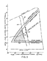
- the system 24 shown in FIG. 2 substantially reduces the size of the envelope of operating conditions during which the compressor bleed valve is closed, when the aircraft is at or above the preselected altitude and is shown as a generally shaded triangular area 43 in FIG. 3. More particularly, as shown in FIG. 3, the bleed will stay closed during a slow deceleration only until a core compressor speed corresponding to the override bleed open line 44 at point 45 is attained, at which time the override bleed valve 32 will immediately open to release air from the compressor. As illustrated in FIG. 3, the override bleed open line 44 at point 45 corresponds to a corrected core compressor speed of about 85%.
- the 85% compressor speed in turn corresponds to a fuel control power lever angle of about 54° during a slow steady state deceleration and is shown as line 44.
- the override bleed valve 32 will quickly open to release air from the compressor at a point prior to the operating condition under which the deceleration surge would occur in a prior art engine.
- a dead band or hysteresis is incorporated into the indirect compressor speed sensor 28 shown in FIG. 2.
- This dead band causes the bleed valve to close during acceleration at a higher compressor speed than the speed at which the bleed valve is opened during deceleration.
- the dead band in the compressor speed sensor 28 effectively establishes an override bleed closed line 46 at which the bleed valve will close during acceleration.
- the bleed valve will close at a corrected compressor speed of about 87% which corresponds approximately to a power lever angle of about 58° and is shown as point 48 on line 46.
- This particular construction ensures that the bleed valve does not repeatedly open and close during a slow acceleration or deceleration.
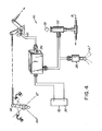
- the system identified generally by the numeral 50 in FIG. 4 is the portion of the subject override system which prevents the high energy surges caused by the small but rapid movements of the power lever at altitude, such as those identified by lines 18, 20 or 22 in FIG. 1. It is noted that the system 50 shown in FIG. 4 and the system 24 shown in FIG. 2 can be used independently even though they are typically used in combination. With reference to FIG. 4, the system 50 comprises an altitude sensor 26, an electrical power source 30 and an override bleed valve 32 identical to like numbered components described above.
- System 50 further includes a rotary potentiometer 52 to convert rotational movement of the power lever, into a variable electric signal, plus a rate detector/time delay device 54 to measure the'period of time over which a particular rate of power lever movement occurs.
- a threshold level of rotational motion by the power lever 38 has been detected while the aircraft is above a preselected altitude pressure 27, the rate detector/time delay device 54 will begin measuring the period of time during which the power lever 38 is moved at the particular rate. If movement of the power lever 38 continues above the minimum power lever rate for at least a minimum response time, a signal will be sent to the override bleed valve 32 causing the override bleed valve 32 to open immediately and vent bleed air 31' into the ambient surroundings 33. The override bleed valve 32 will remain in its open position for a period of time which is a function of the specific power lever rate detected by the rate detector/time delay device 54.
- the operation of the override system illustrated in FIG. 4 is shown graphically in FIG. 5.
- the minimum power lever rate is set to equal approximately plus or minus 3° of power lever movement per second, as indicated by the vertical dashed line at the left hand side of the graph.
- movements of the power lever 38 at rates less than plus or minus 3° per second have no effect on the override bleed valve 32.
- a movement of the power lever 38 in either direction at a rate in excess of 3° per second for a sufficient period of time will cause the override bleed valve 32 to abruptly open.
- the duration of sustained movement of the power lever 38 required to cause the override bleed valve 32 to open is illustrated graphically in FIG.
- response time varies inversely in proportion to the power lever rate.
- the rate must be sustained for a finite period of time, e.g. 0.4 seconds.
- the rate need only be sustained for a very short period of time, e.g. at a rate of plus or minus 10° per second, a response time of only 0.1 seconds is required.
- the override bleed valve 32 remains open for a period of time which varies directly with the rate of power lever movement as illustrated by the line in FIG. 5 identified as "delay time". Once the override valve 32 has been opened, it will remain open for at least a minimum delay time of 1.0-seconds, as illustrated by the horizontal dashed line in FIG. 5. However, the override bleed valve remains open for a proportionally greater periods at higher rates of power lever movement. Thus, referring to the example cited in the previous paragraph, if a power lever rate of plus or minus 10° per second is sustained for at least 0.1 seconds, the override bleed valve 32 will abruptly open and remain open for a period of approximately 1.25 seconds.
- the override bleed valve 32 will abruptly open and remain open for approximately 2.5 seconds.
- the response and delay times of course vary according to the particular engine in which the subject invention is employed. However, the power lever rate and response time curve is selected to anticipate surge and the delay time curve is selected to hold the compressor bleed valve open to release a sufficient amount of air from the compressor and avoid the surge.
- a compressor air bleed override control system is provided to override the primary bleed valve schedule and open the compressor bleed valve quickly when conditions likely to cause surge at altitude occur.
- the apparatus includes an altitude sensor, an electrical power source, a bleed or override valve in communication with the compressor, an indirect core compressor speed sensor and a rate detector for sensing movement of the power lever.
- the altitude sensor is adjusted to enable an appropriate signal to be sent to the override bleed valve when the aircraft is at or above a preselected altitude.
- the indirect core compressor speed sensor is operative to detect a compressor speed which corresponds to a slow deceleration.
- the bleed valve opens suddenly to release air from the compressor prior to the onset of surge.
- the rate detector is operative to measure both the rate of power lever movement and the duration of movements.
- the bleed valve will open quickly to release air from the compressor.
- the bleed valve remains open for a selected period of time which varies according to the rate of power lever movement.
Landscapes
- Engineering & Computer Science (AREA)
- Chemical & Material Sciences (AREA)
- Combustion & Propulsion (AREA)
- Mechanical Engineering (AREA)
- General Engineering & Computer Science (AREA)
- Physics & Mathematics (AREA)
- Fluid Mechanics (AREA)
- Life Sciences & Earth Sciences (AREA)
- Sustainable Development (AREA)
- Control Of Positive-Displacement Air Blowers (AREA)
Applications Claiming Priority (2)
| Application Number | Priority Date | Filing Date | Title |
|---|---|---|---|
| US06/541,226 US4502275A (en) | 1983-10-13 | 1983-10-13 | Compressor air bleed override control system |
| US541226 | 1983-10-13 |
Publications (2)
| Publication Number | Publication Date |
|---|---|
| EP0137614A2 true EP0137614A2 (fr) | 1985-04-17 |
| EP0137614A3 EP0137614A3 (fr) | 1987-05-20 |
Family
ID=24158705
Family Applications (1)
| Application Number | Title | Priority Date | Filing Date |
|---|---|---|---|
| EP84305303A Withdrawn EP0137614A3 (fr) | 1983-10-13 | 1984-08-03 | Commande par priorité pour le soutirage d'air de compresseur |
Country Status (5)
| Country | Link |
|---|---|
| US (1) | US4502275A (fr) |
| EP (1) | EP0137614A3 (fr) |
| JP (1) | JPS6098129A (fr) |
| BR (1) | BR8404804A (fr) |
| CA (1) | CA1225529A (fr) |
Cited By (6)
| Publication number | Priority date | Publication date | Assignee | Title |
|---|---|---|---|---|
| FR2581425A1 (fr) * | 1985-05-03 | 1986-11-07 | Gen Electric | Reacteur a soufflante non canalisee ayant un nombre de mach eleve |
| EP0298895A3 (en) * | 1987-07-08 | 1989-11-23 | United Technologies Corporation | Control system for a gas turbine engine |
| EP0539285A1 (fr) * | 1991-10-23 | 1993-04-28 | Societe Nationale D'etude Et De Construction De Moteurs D'aviation "Snecma" | Dispositif de commande de l'ouverture et de la fermeture des vannes de décharge d'un turboréacteur |
| GB2273316A (en) * | 1992-12-12 | 1994-06-15 | Rolls Royce Plc | Anti-surge bleed valve control in a gas turbine compressor |
| US5515673A (en) * | 1991-10-23 | 1996-05-14 | Societe Nationale D'etude Et De Construction De Moteurs D'aviation "S.N.E.C.M.A" | Device for controlling the opening and closing of discharge valves of a turbojet engine |
| US8011382B2 (en) | 2008-10-06 | 2011-09-06 | Honeywell International Inc. | Bi-modal bleed valve assembly for gas turbine engine |
Families Citing this family (7)
| Publication number | Priority date | Publication date | Assignee | Title |
|---|---|---|---|---|
| GB8510832D0 (en) * | 1985-04-29 | 1985-06-05 | Bio Medical Res Ltd | Electrical stimulation of muscle |
| US4864813A (en) * | 1987-07-08 | 1989-09-12 | United Technologies Corporation | Control system for a gas turbine engine |
| US5313778A (en) * | 1992-12-10 | 1994-05-24 | United Technologies Corporation | Automatic turbine engine bleed valve control for enhanced fuel management |
| US20060207656A1 (en) * | 2005-03-15 | 2006-09-21 | Akihiko Takahashi | Air bleeding pipe joint |
| US9611752B2 (en) | 2013-03-15 | 2017-04-04 | General Electric Company | Compressor start bleed system for a turbine system and method of controlling a compressor start bleed system |
| FR3063782B1 (fr) * | 2017-03-07 | 2021-06-18 | Safran Aircraft Engines | Procede et dispositif de detection de conditions propices a l'apparition d'un pompage en vue de proteger un compresseur d'une turbomachine d'aeronef |
| US11220357B2 (en) * | 2019-01-18 | 2022-01-11 | The Boeing Company | Aircraft maintenance systems and methods |
Family Cites Families (7)
| Publication number | Priority date | Publication date | Assignee | Title |
|---|---|---|---|---|
| US2965285A (en) * | 1955-10-10 | 1960-12-20 | Holley Carburetor Co | Compressor bleed control |
| US2978166A (en) * | 1957-05-28 | 1961-04-04 | Gen Motors Corp | Compressor bleed control |
| US3006145A (en) * | 1959-10-14 | 1961-10-31 | Gen Motors Corp | Antisurge control using compressor bleed |
| US3893292A (en) * | 1973-08-06 | 1975-07-08 | Gen Motors Corp | Power turbine deceleration control |
| US3971208A (en) * | 1974-04-01 | 1976-07-27 | The Garrett Corporation | Gas turbine fuel control |
| US4117668A (en) * | 1975-11-19 | 1978-10-03 | United Technologies Corporation | Stall detector for gas turbine engine |
| US4251985A (en) * | 1979-07-17 | 1981-02-24 | General Motors Corporation | Bleed valve control circuit |
-
1983
- 1983-10-13 US US06/541,226 patent/US4502275A/en not_active Expired - Lifetime
-
1984
- 1984-08-03 EP EP84305303A patent/EP0137614A3/fr not_active Withdrawn
- 1984-09-19 CA CA000463587A patent/CA1225529A/fr not_active Expired
- 1984-09-25 BR BR8404804A patent/BR8404804A/pt unknown
- 1984-10-11 JP JP59211576A patent/JPS6098129A/ja active Pending
Cited By (8)
| Publication number | Priority date | Publication date | Assignee | Title |
|---|---|---|---|---|
| FR2581425A1 (fr) * | 1985-05-03 | 1986-11-07 | Gen Electric | Reacteur a soufflante non canalisee ayant un nombre de mach eleve |
| EP0298895A3 (en) * | 1987-07-08 | 1989-11-23 | United Technologies Corporation | Control system for a gas turbine engine |
| EP0539285A1 (fr) * | 1991-10-23 | 1993-04-28 | Societe Nationale D'etude Et De Construction De Moteurs D'aviation "Snecma" | Dispositif de commande de l'ouverture et de la fermeture des vannes de décharge d'un turboréacteur |
| FR2682995A1 (fr) * | 1991-10-23 | 1993-04-30 | Snecma | Dispositif de commande de l'ouverture et de la fermeture des vannes de decharge d'un turboreacteur. |
| US5515673A (en) * | 1991-10-23 | 1996-05-14 | Societe Nationale D'etude Et De Construction De Moteurs D'aviation "S.N.E.C.M.A" | Device for controlling the opening and closing of discharge valves of a turbojet engine |
| GB2273316A (en) * | 1992-12-12 | 1994-06-15 | Rolls Royce Plc | Anti-surge bleed valve control in a gas turbine compressor |
| GB2273316B (en) * | 1992-12-12 | 1996-02-28 | Rolls Royce Plc | Bleed valve control |
| US8011382B2 (en) | 2008-10-06 | 2011-09-06 | Honeywell International Inc. | Bi-modal bleed valve assembly for gas turbine engine |
Also Published As
| Publication number | Publication date |
|---|---|
| US4502275A (en) | 1985-03-05 |
| EP0137614A3 (fr) | 1987-05-20 |
| JPS6098129A (ja) | 1985-06-01 |
| CA1225529A (fr) | 1987-08-18 |
| BR8404804A (pt) | 1985-08-13 |
Similar Documents
| Publication | Publication Date | Title |
|---|---|---|
| US4502275A (en) | Compressor air bleed override control system | |
| EP2064434B1 (fr) | Gestion de la ligne de fonctionnement d'un compresseur basse pression dans un moteur de turboréacteur à double flux | |
| JP5552002B2 (ja) | サージマージン制御 | |
| EP2881546A1 (fr) | Commande de moteur de turbine à gaz | |
| US5226287A (en) | Compressor stall recovery apparatus | |
| US3006145A (en) | Antisurge control using compressor bleed | |
| US10823113B2 (en) | Method and system for limiting power of an engine | |
| CA3080290A1 (fr) | Procede de commande d`une helice dotee d`une vanne electromagnetique a deux positions | |
| CN111924127B (zh) | 检测飞行器中的无命令或不可控高推力事件的系统和方法 | |
| US3677000A (en) | System for the detection and control of compressor stall | |
| WO1993016917A1 (fr) | Turbine a pression dynamique compacte axialement | |
| US8800295B2 (en) | Device and a method for regulating a turbine engine, and an aircraft | |
| CA3107034A1 (fr) | Systeme et methode pour surveiller un robinet de purge d`une turbine a gaz | |
| US11512650B2 (en) | Method and device for detecting conditions conducive to the onset of pumping with a view to protecting a compressor of an aircraft turbine engine | |
| US4722180A (en) | Method and means for enhancing recovery of a surge condition in a gas turbine engine | |
| US4768338A (en) | Means for enhancing recovery of a surge condition in a gas turbine engine | |
| US5205116A (en) | Compressor stall recovery apparatus | |
| USRE31835E (en) | Pneumatic supply system having variable geometry compressor | |
| WO2008063153A2 (fr) | Régulation de la vitesse maximale d'une turbine basse pression dans un turboréacteur de | |
| EP2074301A1 (fr) | Réduction de longueur de piste nécessaire au décollage au moyen d'une tuyère variable | |
| US5269136A (en) | Sub-idle stability enhancement and rotating stall recovery | |
| US3155165A (en) | Turboprop engine control with underspeed governor | |
| CN110886659A (zh) | 用于限制发动机功率的方法及系统 | |
| JP2002285908A (ja) | タ−ボファンエンジンのスト−ルマ−ジン制御装置 | |
| GB2128771A (en) | Fuel control system for a gas turbine engine |
Legal Events
| Date | Code | Title | Description |
|---|---|---|---|
| PUAI | Public reference made under article 153(3) epc to a published international application that has entered the european phase |
Free format text: ORIGINAL CODE: 0009012 |
|
| AK | Designated contracting states |
Designated state(s): DE FR GB IT SE |
|
| 17P | Request for examination filed |
Effective date: 19850528 |
|
| PUAL | Search report despatched |
Free format text: ORIGINAL CODE: 0009013 |
|
| AK | Designated contracting states |
Kind code of ref document: A3 Designated state(s): DE FR GB IT SE |
|
| STAA | Information on the status of an ep patent application or granted ep patent |
Free format text: STATUS: THE APPLICATION HAS BEEN WITHDRAWN |
|
| 18W | Application withdrawn |
Withdrawal date: 19870831 |
|
| RIN1 | Information on inventor provided before grant (corrected) |
Inventor name: PETRO, DAVID J. |