EP0137848B1 - Vorrichtung zur vernichtung von mikroorganismen - Google Patents
Vorrichtung zur vernichtung von mikroorganismen Download PDFInfo
- Publication number
- EP0137848B1 EP0137848B1 EP84901632A EP84901632A EP0137848B1 EP 0137848 B1 EP0137848 B1 EP 0137848B1 EP 84901632 A EP84901632 A EP 84901632A EP 84901632 A EP84901632 A EP 84901632A EP 0137848 B1 EP0137848 B1 EP 0137848B1
- Authority
- EP
- European Patent Office
- Prior art keywords
- chamber
- minor
- outlet
- inlet
- chambers
- Prior art date
- Legal status (The legal status is an assumption and is not a legal conclusion. Google has not performed a legal analysis and makes no representation as to the accuracy of the status listed.)
- Expired
Links
Images

Classifications
-
- C—CHEMISTRY; METALLURGY
- C02—TREATMENT OF WATER, WASTE WATER, SEWAGE, OR SLUDGE
- C02F—TREATMENT OF WATER, WASTE WATER, SEWAGE, OR SLUDGE
- C02F1/00—Treatment of water, waste water, or sewage
- C02F1/30—Treatment of water, waste water, or sewage by irradiation
- C02F1/32—Treatment of water, waste water, or sewage by irradiation with ultraviolet light
- C02F1/325—Irradiation devices or lamp constructions
-
- A—HUMAN NECESSITIES
- A61—MEDICAL OR VETERINARY SCIENCE; HYGIENE
- A61L—METHODS OR APPARATUS FOR STERILISING MATERIALS OR OBJECTS IN GENERAL; DISINFECTION, STERILISATION OR DEODORISATION OF AIR; CHEMICAL ASPECTS OF BANDAGES, DRESSINGS, ABSORBENT PADS OR SURGICAL ARTICLES; MATERIALS FOR BANDAGES, DRESSINGS, ABSORBENT PADS OR SURGICAL ARTICLES
- A61L2/00—Disinfection or sterilisation of materials or objects, in general; Accessories therefor
- A61L2/02—Disinfection or sterilisation of materials or objects, in general; Accessories therefor using physical processes
- A61L2/08—Radiation
- A61L2/10—Ultraviolet [UV] radiation
-
- A—HUMAN NECESSITIES
- A61—MEDICAL OR VETERINARY SCIENCE; HYGIENE
- A61L—METHODS OR APPARATUS FOR STERILISING MATERIALS OR OBJECTS IN GENERAL; DISINFECTION, STERILISATION OR DEODORISATION OF AIR; CHEMICAL ASPECTS OF BANDAGES, DRESSINGS, ABSORBENT PADS OR SURGICAL ARTICLES; MATERIALS FOR BANDAGES, DRESSINGS, ABSORBENT PADS OR SURGICAL ARTICLES
- A61L9/00—Disinfection, sterilisation or deodorisation of air
- A61L9/16—Disinfection, sterilisation or deodorisation of air using physical phenomena
- A61L9/18—Radiation
- A61L9/20—Ultraviolet radiation
-
- C—CHEMISTRY; METALLURGY
- C02—TREATMENT OF WATER, WASTE WATER, SEWAGE, OR SLUDGE
- C02F—TREATMENT OF WATER, WASTE WATER, SEWAGE, OR SLUDGE
- C02F2201/00—Apparatus for treatment of water, waste water or sewage
- C02F2201/32—Details relating to UV-irradiation devices
- C02F2201/322—Lamp arrangement
- C02F2201/3223—Single elongated lamp located on the central axis of a turbular reactor
Definitions
- the present invention relates to apparatus according to the accompanying claim.
- Such materials as liquids (water) and gases (air) can be cleansed of undesirable microorganisms by irradiation with ultra-violet light of wavelengths shorter than 320 nm. Irradiation is effected with the aid of a so-called ultra-violet lamp.
- the present invention has been developed in conjunction with such bacteria-destroying apparatus.
- the radiation chamber may incorporate either a single long UV- tube or a plurality of shorter tubes. This, however, increases plant costs to an unacceptable level. It is the problem of plant costs which has engendered the present invention.
- the apparatus can be used to treat both liquids and gases, there will be first described an apparatus for treating liquids, followed by a description of a gas-treating apparatus. Irradiation of liquids
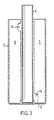
- the irradiation chamber also known as a UV- chamber, comprises a substantially vertically arranged vessel 1, which is sealed at both ends; at the bottom by means of a permanent wall 2 and at the top by means of a tightly fitting cap 3 provided with requisite sealing means.
- the irradiation chamber is made of a material suitable for ultra-violet radiation.
- quartz-crystal glass tube 4 Placed in a known manner centrally of the chamber is a quartz-crystal glass tube 4 having a UV-Iamp 5 arranged therein.
- the quartz-crystal glass tube is completely sealed at the bottom thereof, and extends substantially to the bottom 2 of the chamber 1, where it is anchored in a known manner.
- the quartz-crystal glass tube 4 extends upwardly through the gap 3, which is provided with suitable sealing means not shown.
- the UV-Iamp 5 is mounted within the quartz-crystal glass tube 4, and the length dimensions of the lamp are substantially the same as those of the glass tube 4.
- the UV-Iamp 5 is connected to a lamp holder in a known manner, not shown. Neither are those electrical connections shown which are known or which are not directly associated with the concept of the invention.
- the quartz-crystal glass tube 4 together with the UV- lamp 5 can be readily mounted in position and dismantled when it is necessary to clean, primarily, the quartz-crystal glass tube.
- the UV-Iamp can be changed in the normal fashion.
- the radiation chamber 1 can be provided, in a known manner, with a photocell arranged to function as a signal guard and a means for monitoring purification.
- the walls 6-10 extend radially in the chamber 1 and are sealingly connected to the cylinder wall 1', and the bottom wall 2 thereof.
- the tops of the walls are sealingly connected to the cap 3 of the chamber 1 thorugh the agency of separate sealing means, such as the illustrated seal 13 for example.
- An annular gap has been left between the walls 6-10 inclusive and the quartz-crystal glass tube 4, to facilitate assembly and dismantling of the radiation chamber.
- the major irradiation chamber has been divided into five minor irradiation chambers, referenced A, B, C, D and E on the drawing.
- an opening 14 Arranged in the upper part of wall 6 is an opening 14, which connects the chamber A with chamber B.
- a similar opening 15 connecting chamber B with chamber C is arranged in the lower part of the wall 7.
- the openings 14 and 15 are located adjacent the tube 4 and preferably extend radially no further from said tube than a limited part of the radial distance from the tube 4 to the cylinder wall 1'.
- the partition wall 8 has an upper opening 14 similar to that of the wall 6, while the partition wall 9 has a lower opening 15, similar to that of the wall 7. There is no connection in the partition wall 10 affording communication between mutually adjacent chambers A and E.
- connection or inlet 11 Arranged in the lower part of the major chamber 1 is a connection or inlet 11, which communicates with the chamber A.
- An outlet 12 communicating with the chamber E is arranged in the upper part of the major chamber 1, in the illustrated embodiment the outlet 12 is located in the cap 3.
- the liquid to be irradiated with ultra-violet rays is passed through the inlet 11 and into the chamber A.
- the liquid in chamber A will travel upwards, while as a result of the bottom connection 15 of chamber B with chamber C, the liquid in chamber B will move downwards.
- the liquid in chamber C will again move in an upward direction, as a result of the connection between the chambers C and D, while the liquid in chamber D will move downwards, as a result of the bottom connection between the chambers D and E.
- Liquid in the chamber E will move upwardly therein and exit through the outlet 12 connected therewith.
- the inlet 11 is suitably located in the lower part of the major chamber 1 and the outlet 12 in the upper part thereof, such as to ensure total filling of said chamber.
- This arrangement requires the number of partition walls provided to be an odd number.
- the plant may be operated intermittently. When the plant is started up, there will be a certain delay before the UV-Iamp 5 has full effect. Consequently, it is essential that the flow of liquid has a relatively long path to travel along the UV- lamp 5, so as to obtain the intended exposure time. That liquid found adjacent the outlet 12 and deriving from an immediately preceding, terminated working operation has earlier been exposed to a full dosage of radiation, from the lamp 5. Irradiation of gases
- the same apparatus as that used to irradiate liquids with ultra-violet rays can also be used to irradiate gases.
- the major irradiation chamber 1 can be oriented in any desired direction. Since gas will naturally pervade the irradiation chamber, to completely fill said chamber, the inlet and outlet can be optionally placed on mutually opposite sides of the irradiation chamber 1, or on the same side thereof. This enables the provision of any desired number of partition walls.
- the operational mode of the plant in respect of gases is the same as that previously described in respect of liquids.
- the major irradiation chamber 1 may also be provided with sealing means between the quartz-crystal glass tube 4 and each partition wall, from 6 to 10 inclusive. The aforedescribed communication parts between the minor chambers are retained.
- This embodiment enables the major irradiation chamber 1 to be oriented in any desired direction. Similarly, there is afforded a freedom of choice with respect to the number of minor chambers (A to E) provided, allowing the inlet and outlet to be placed on one and the same side or on mutually opposite sides. The arrangement always ensures that the major chamber is completely filled.
- the major irraditation chamber may have a different shape to the illustrated circular-cylindrical shape, for example a hexagonal or an octagonal shape.
- the number of partition walls provided may be different from five, even in the case of a circular-cylindrical major chamber.
- the guard around the lamp may be of some other design, or optionally the lamp may be used without a separate guard.
Landscapes
- Health & Medical Sciences (AREA)
- Life Sciences & Earth Sciences (AREA)
- Epidemiology (AREA)
- Animal Behavior & Ethology (AREA)
- General Health & Medical Sciences (AREA)
- Public Health (AREA)
- Veterinary Medicine (AREA)
- Hydrology & Water Resources (AREA)
- Toxicology (AREA)
- Engineering & Computer Science (AREA)
- Environmental & Geological Engineering (AREA)
- Water Supply & Treatment (AREA)
- Chemical & Material Sciences (AREA)
- Organic Chemistry (AREA)
- Physical Water Treatments (AREA)
- Physical Or Chemical Processes And Apparatus (AREA)
- Apparatus Associated With Microorganisms And Enzymes (AREA)
- Apparatus For Disinfection Or Sterilisation (AREA)
Claims (5)
Priority Applications (1)
| Application Number | Priority Date | Filing Date | Title |
|---|---|---|---|
| AT84901632T ATE46308T1 (de) | 1983-03-30 | 1984-03-29 | Vorrichtung zur vernichtung von mikroorganismen. |
Applications Claiming Priority (2)
| Application Number | Priority Date | Filing Date | Title |
|---|---|---|---|
| SE8301762 | 1983-03-30 | ||
| SE8301762A SE8301762L (sv) | 1983-03-30 | 1983-03-30 | Anordning vid forstoring av mikroorganismer |
Publications (2)
| Publication Number | Publication Date |
|---|---|
| EP0137848A1 EP0137848A1 (de) | 1985-04-24 |
| EP0137848B1 true EP0137848B1 (de) | 1989-09-13 |
Family
ID=20350602
Family Applications (1)
| Application Number | Title | Priority Date | Filing Date |
|---|---|---|---|
| EP84901632A Expired EP0137848B1 (de) | 1983-03-30 | 1984-03-29 | Vorrichtung zur vernichtung von mikroorganismen |
Country Status (6)
| Country | Link |
|---|---|
| US (1) | US4621195A (de) |
| EP (1) | EP0137848B1 (de) |
| DE (1) | DE3479718D1 (de) |
| DK (1) | DK160128C (de) |
| SE (1) | SE8301762L (de) |
| WO (1) | WO1984003880A1 (de) |
Families Citing this family (37)
| Publication number | Priority date | Publication date | Assignee | Title |
|---|---|---|---|---|
| GB2175777A (en) * | 1985-05-24 | 1986-12-03 | Still & Sons Ltd W M | Improvements in and relating to water purifiers |
| DE3677885D1 (de) * | 1985-10-14 | 1991-04-11 | Ubirajara Keutenedjian | Vorrichtung zur luftreinigung mit ultraviolettstrahlung. |
| US4853581A (en) * | 1986-02-10 | 1989-08-01 | Photo Redux Corp. | Radiation-emitting devices |
| US5150705A (en) * | 1989-07-12 | 1992-09-29 | Stinson Randy L | Apparatus and method for irradiating cells |
| MY108087A (en) * | 1989-07-12 | 1996-08-15 | Randy L Stinson | Apparatus and method for irradiating cells. |
| US5503721A (en) * | 1991-07-18 | 1996-04-02 | Hri Research, Inc. | Method for photoactivation |
| US5184020A (en) * | 1989-10-26 | 1993-02-02 | Hearst David P | Device and method for photoactivation |
| DE4012398A1 (de) * | 1990-04-19 | 1991-10-24 | Waelischmiller Hans Dipl Ing F | Bestrahlungsvorrichtung |
| US5208461A (en) * | 1991-10-03 | 1993-05-04 | Simon Hydro-Aerobics, Inc. | Ultra-violet wastewater disinfection system |
| US6433343B1 (en) | 1992-03-02 | 2002-08-13 | Cerus Corporation | Device and method for photoactivation |
| US5449466A (en) * | 1993-04-23 | 1995-09-12 | American Energy Technologies, Inc. | Apparatus and method for photocatalytic treatment of a fluid |
| US6146600A (en) * | 1993-09-17 | 2000-11-14 | University Of Hawaii | Side body disingestation chamber |
| NZ271896A (en) * | 1993-09-17 | 1998-02-26 | Univ Hawaii | Pest treatment chamber; apparatus for killing pests on or in flowers, fruit or vegetable commodities; use of hot air with a relative humidity of 30-85% |
| WO1995033500A1 (en) * | 1994-06-02 | 1995-12-14 | Monagan Gerald C | Air purifier |
| US5792433A (en) * | 1995-03-13 | 1998-08-11 | Photoscience Japan Corporation | Light irradiating device with easily replaceable light irradiating lamps |
| US6053968A (en) * | 1998-10-14 | 2000-04-25 | Miller; Bob C. | Portable room air purifier |
| US6296775B1 (en) | 1998-11-09 | 2001-10-02 | Kenneth W. Moody | Apparatus and method for UV wastewater purification in septic tank systems |
| US6613277B1 (en) | 1999-06-18 | 2003-09-02 | Gerald C. Monagan | Air purifier |
| US6264836B1 (en) | 1999-10-21 | 2001-07-24 | Robert M. Lantis | Method and apparatus for decontaminating fluids using ultraviolet radiation |
| CA2341089C (en) * | 2001-03-16 | 2002-07-02 | Calgon Carbon Corporation | Ship ballast water sterilization method and system |
| AT411250B (de) * | 2002-02-06 | 2003-11-25 | Szechenyi Ferdinand | Einrichtung zur entkeimung eines fluids |
| US6784440B2 (en) | 2002-07-26 | 2004-08-31 | Boc, Inc. | Food sanitizing cabinet |
| US7160566B2 (en) | 2003-02-07 | 2007-01-09 | Boc, Inc. | Food surface sanitation tunnel |
| WO2004101101A2 (en) | 2003-05-08 | 2004-11-25 | Eco-Rx, Inc. | System for purifying and removing contaminants from gaseous fluids |
| JP2007511253A (ja) | 2003-06-12 | 2007-05-10 | セーフ ヘイブン インコーポレイテッド | 空気及び物体の殺菌方法及び装置 |
| US10133173B2 (en) * | 2012-09-27 | 2018-11-20 | SCREEN Holdings Co., Ltd. | Processing fluid supply device, substrate processing device, processing fluid supply method, substrate processing method, processing fluid processing device, and processing fluid processing method |
| US9457119B2 (en) | 2012-12-11 | 2016-10-04 | Aerobiotix, Inc. | Fluid sterilization system |
| WO2014190066A1 (en) | 2013-05-22 | 2014-11-27 | Aerobiotix, Llc | An air-surface disinfection system, unit and method |
| GB2545215A (en) * | 2015-12-09 | 2017-06-14 | Primeco Sa | Device for the hygienisation of post-fermentation sludge from biogas plant |
| US11052168B2 (en) | 2016-11-16 | 2021-07-06 | Aerobiotix, Inc. | Air germicidal device |
| US10702435B2 (en) | 2016-11-16 | 2020-07-07 | Thunderhill Investments, LLC | Medical air treatment device |
| CA2970494A1 (en) | 2017-06-09 | 2018-12-09 | Ebbtides Medical Inc. | Ultraviolet light water treatment unit for high flow rate systems |
| CN210012631U (zh) * | 2018-10-31 | 2020-02-04 | 厦门百霖净水科技有限公司 | 一种带uv灯的过滤装置 |
| WO2020164646A1 (en) * | 2019-02-11 | 2020-08-20 | Jiri Drimal | Apparatus for treatment of liquids |
| EP4076547A1 (de) | 2019-12-17 | 2022-10-26 | Aerobiotix, Inc. | Medizinisches luftbehandlungssystem mit laminarer strömung und energiebasierter luftdekontamination |
| USD978313S1 (en) | 2020-05-11 | 2023-02-14 | Aerobiotix, Llc | Air cleaner |
| JP7255004B1 (ja) | 2022-08-05 | 2023-04-10 | ナカ電子株式会社 | 紫外線照射によるウイルス不活化装置および方法 |
Citations (2)
| Publication number | Priority date | Publication date | Assignee | Title |
|---|---|---|---|---|
| FR1359259A (fr) * | 1963-03-13 | 1964-04-24 | Appareil de stérilisation des eaux par les rayons ultra-violets | |
| WO1983002937A1 (en) * | 1982-02-17 | 1983-09-01 | Zamburro, Frank | Water purifying apparatus |
Family Cites Families (15)
| Publication number | Priority date | Publication date | Assignee | Title |
|---|---|---|---|---|
| DE278368C (de) * | 1910-01-31 | |||
| US1473095A (en) * | 1910-10-31 | 1923-11-06 | Henri Victor | Apparatus for sterilizing liquids by means of ultra-violet rays |
| US1200940A (en) * | 1910-10-31 | 1916-10-10 | R U V Company Inc | Apparatus for the treatment of water and other liquids by ultra-violet rays. |
| DE258685C (de) * | 1911-03-06 | |||
| US1196481A (en) * | 1912-12-21 | 1916-08-29 | R U V Company Inc | Sterilization of liquids. |
| US1266803A (en) * | 1917-08-13 | 1918-05-21 | R U V Company Inc | Treatment of water and other liquids by ultra-violet rays. |
| FR550725A (fr) * | 1923-04-23 | 1923-03-16 | Appareil pour la stérilisation des liquides par les rayons ultra-violets | |
| US2065055A (en) * | 1934-06-07 | 1936-12-22 | R U V Engineering Corp | Irradiating apparatus |
| US3079498A (en) * | 1960-07-15 | 1963-02-26 | Ruffin Hoebel Corp | Swimming pool water purifier |
| US3462597A (en) * | 1966-07-29 | 1969-08-19 | Ultra Dynamics Corp | Ultraviolet fluid purifier having manually operable wiper means |
| CA966608A (en) * | 1972-11-20 | 1975-04-29 | Naturvard Research (Canada) Ltd. | Automatic tube cleaner for water sterilizer |
| AU456160B2 (en) * | 1974-04-19 | 1974-12-12 | Myron Dale Woodand Harold Meltzer | Process and apparatus for purification of materials |
| US4151090A (en) * | 1974-05-30 | 1979-04-24 | Brigante Miguel F | Unitary package for water treatment for attachment to home hot water heater |
| CA1009019A (en) * | 1974-10-03 | 1977-04-26 | David Free | Fluid flow diffuser plate |
| US4278549A (en) * | 1979-11-19 | 1981-07-14 | Abrams Joseph L | Magnetic conditioning of liquids |
-
1983
- 1983-03-30 SE SE8301762A patent/SE8301762L/ unknown
-
1984
- 1984-03-29 EP EP84901632A patent/EP0137848B1/de not_active Expired
- 1984-03-29 WO PCT/SE1984/000116 patent/WO1984003880A1/en not_active Ceased
- 1984-03-29 US US06/679,045 patent/US4621195A/en not_active Expired - Fee Related
- 1984-03-29 DE DE8484901632T patent/DE3479718D1/de not_active Expired
- 1984-11-14 DK DK541684A patent/DK160128C/da not_active IP Right Cessation
Patent Citations (2)
| Publication number | Priority date | Publication date | Assignee | Title |
|---|---|---|---|---|
| FR1359259A (fr) * | 1963-03-13 | 1964-04-24 | Appareil de stérilisation des eaux par les rayons ultra-violets | |
| WO1983002937A1 (en) * | 1982-02-17 | 1983-09-01 | Zamburro, Frank | Water purifying apparatus |
Also Published As
| Publication number | Publication date |
|---|---|
| DK541684A (da) | 1984-11-14 |
| US4621195A (en) | 1986-11-04 |
| DE3479718D1 (en) | 1989-10-19 |
| SE8301762L (sv) | 1984-10-01 |
| WO1984003880A1 (en) | 1984-10-11 |
| DK160128C (da) | 1991-07-08 |
| DK541684D0 (da) | 1984-11-14 |
| SE8301762D0 (sv) | 1983-03-30 |
| DK160128B (da) | 1991-02-04 |
| EP0137848A1 (de) | 1985-04-24 |
Similar Documents
| Publication | Publication Date | Title |
|---|---|---|
| US4621195A (en) | Apparatus for destroying microorganisms | |
| US4179616A (en) | Apparatus for sanitizing liquids with ultra-violet radiation and ozone | |
| US5626768A (en) | Sterilization of opaque liquids with ultraviolet radiation | |
| US3836781A (en) | Irradiator for water purification | |
| CA2204435A1 (en) | Improved lamp cooling for a uv lamp reactor assembly | |
| US4968891A (en) | Disinfecting a fluid with ultraviolet radiation | |
| EP0435907A1 (de) | Oxydationskammer. | |
| US4201917A (en) | Apparatus for irradiation of fluids | |
| CA1081913A (en) | Apparatus for sanitizing liquids | |
| US4601822A (en) | Water purifying apparatus | |
| KR100392413B1 (ko) | 기체및액체의정화방법및장치 | |
| US5063030A (en) | Process and apparatus for removing organic contaminants from a fluid | |
| EP0467465A1 (de) | Sterilisator | |
| US5861123A (en) | Ultraviolet light irradiated ebullating mass transfer system | |
| US1266803A (en) | Treatment of water and other liquids by ultra-violet rays. | |
| AU672594B2 (en) | UV reactor assembly | |
| US6348151B1 (en) | Device for sterilizing and filtering water which flows through a sanitary device | |
| JPH11290844A (ja) | 光触媒反応水処理装置 | |
| JP2000159508A (ja) | オゾン発生装置 | |
| KR100348414B1 (ko) | 용해기 및 상기 용해기를 구비하는 수처리 장치 | |
| NO157859B (no) | Apparat for dreping av mikroorganismer. | |
| RU239025U1 (ru) | Установка обеззараживания воды | |
| RU2225364C1 (ru) | Устройство для ультрафиолетового обеззараживания воды | |
| Ellison | Irradiator for water purification | |
| RU2045296C1 (ru) | Аппарат для ультрафиолетового облучения крови и других биологических жидкостей |
Legal Events
| Date | Code | Title | Description |
|---|---|---|---|
| PUAI | Public reference made under article 153(3) epc to a published international application that has entered the european phase |
Free format text: ORIGINAL CODE: 0009012 |
|
| AK | Designated contracting states |
Designated state(s): AT BE CH DE FR GB LI NL SE |
|
| 17P | Request for examination filed |
Effective date: 19850401 |
|
| GRAA | (expected) grant |
Free format text: ORIGINAL CODE: 0009210 |
|
| AK | Designated contracting states |
Kind code of ref document: B1 Designated state(s): AT BE CH DE FR GB LI NL SE |
|
| REF | Corresponds to: |
Ref document number: 46308 Country of ref document: AT Date of ref document: 19890915 Kind code of ref document: T |
|
| ET | Fr: translation filed | ||
| REF | Corresponds to: |
Ref document number: 3479718 Country of ref document: DE Date of ref document: 19891019 |
|
| PLBE | No opposition filed within time limit |
Free format text: ORIGINAL CODE: 0009261 |
|
| STAA | Information on the status of an ep patent application or granted ep patent |
Free format text: STATUS: NO OPPOSITION FILED WITHIN TIME LIMIT |
|
| 26N | No opposition filed | ||
| PGFP | Annual fee paid to national office [announced via postgrant information from national office to epo] |
Ref country code: BE Payment date: 19901221 Year of fee payment: 8 |
|
| PGFP | Annual fee paid to national office [announced via postgrant information from national office to epo] |
Ref country code: FR Payment date: 19901226 Year of fee payment: 8 |
|
| PGFP | Annual fee paid to national office [announced via postgrant information from national office to epo] |
Ref country code: CH Payment date: 19910118 Year of fee payment: 8 |
|
| PGFP | Annual fee paid to national office [announced via postgrant information from national office to epo] |
Ref country code: AT Payment date: 19910311 Year of fee payment: 8 |
|
| PGFP | Annual fee paid to national office [announced via postgrant information from national office to epo] |
Ref country code: GB Payment date: 19910321 Year of fee payment: 8 |
|
| PGFP | Annual fee paid to national office [announced via postgrant information from national office to epo] |
Ref country code: DE Payment date: 19910328 Year of fee payment: 8 |
|
| PGFP | Annual fee paid to national office [announced via postgrant information from national office to epo] |
Ref country code: NL Payment date: 19910331 Year of fee payment: 8 |
|
| PGFP | Annual fee paid to national office [announced via postgrant information from national office to epo] |
Ref country code: SE Payment date: 19920323 Year of fee payment: 9 |
|
| PG25 | Lapsed in a contracting state [announced via postgrant information from national office to epo] |
Ref country code: GB Effective date: 19920329 Ref country code: AT Effective date: 19920329 |
|
| PG25 | Lapsed in a contracting state [announced via postgrant information from national office to epo] |
Ref country code: LI Effective date: 19920331 Ref country code: CH Effective date: 19920331 Ref country code: BE Effective date: 19920331 |
|
| BERE | Be: lapsed |
Owner name: L.P. LARSSON A.B. Effective date: 19920331 |
|
| PG25 | Lapsed in a contracting state [announced via postgrant information from national office to epo] |
Ref country code: NL Effective date: 19921001 |
|
| NLV4 | Nl: lapsed or anulled due to non-payment of the annual fee | ||
| GBPC | Gb: european patent ceased through non-payment of renewal fee | ||
| PG25 | Lapsed in a contracting state [announced via postgrant information from national office to epo] |
Ref country code: FR Effective date: 19921130 |
|
| REG | Reference to a national code |
Ref country code: CH Ref legal event code: PL |
|
| PG25 | Lapsed in a contracting state [announced via postgrant information from national office to epo] |
Ref country code: DE Effective date: 19921201 |
|
| REG | Reference to a national code |
Ref country code: FR Ref legal event code: ST |
|
| PG25 | Lapsed in a contracting state [announced via postgrant information from national office to epo] |
Ref country code: SE Effective date: 19930330 |
|
| EUG | Se: european patent has lapsed |
Ref document number: 84901632.4 Effective date: 19931008 |
|
| APAH | Appeal reference modified |
Free format text: ORIGINAL CODE: EPIDOSCREFNO |