EP0137858A2 - Dispositif et méthode de fabrication d'un panneau continu et revêtu de bois à partir des lamelles de bois - Google Patents
Dispositif et méthode de fabrication d'un panneau continu et revêtu de bois à partir des lamelles de bois Download PDFInfo
- Publication number
- EP0137858A2 EP0137858A2 EP83108646A EP83108646A EP0137858A2 EP 0137858 A2 EP0137858 A2 EP 0137858A2 EP 83108646 A EP83108646 A EP 83108646A EP 83108646 A EP83108646 A EP 83108646A EP 0137858 A2 EP0137858 A2 EP 0137858A2
- Authority
- EP
- European Patent Office
- Prior art keywords
- blocks
- ram member
- glue
- pressing plate
- longitudinally
- Prior art date
- Legal status (The legal status is an assumption and is not a legal conclusion. Google has not performed a legal analysis and makes no representation as to the accuracy of the status listed.)
- Withdrawn
Links
- 238000000034 method Methods 0.000 title claims abstract description 16
- 239000007787 solid Substances 0.000 title claims abstract description 12
- 238000003825 pressing Methods 0.000 claims abstract description 32
- 239000003292 glue Substances 0.000 claims abstract description 24
- 230000033001 locomotion Effects 0.000 claims abstract description 20
- 238000001723 curing Methods 0.000 claims description 11
- 239000002023 wood Substances 0.000 claims description 6
- 230000000694 effects Effects 0.000 claims description 4
- 238000013007 heat curing Methods 0.000 claims description 2
- 239000011347 resin Substances 0.000 claims description 2
- 229920005989 resin Polymers 0.000 claims description 2
- 230000000717 retained effect Effects 0.000 claims description 2
- 230000005672 electromagnetic field Effects 0.000 claims 2
- 239000011248 coating agent Substances 0.000 claims 1
- 238000000576 coating method Methods 0.000 claims 1
- 238000004519 manufacturing process Methods 0.000 description 3
- XSQUKJJJFZCRTK-UHFFFAOYSA-N Urea Chemical compound NC(N)=O XSQUKJJJFZCRTK-UHFFFAOYSA-N 0.000 description 2
- 239000004202 carbamide Substances 0.000 description 2
- 238000010276 construction Methods 0.000 description 2
- 230000005611 electricity Effects 0.000 description 2
- 235000000396 iron Nutrition 0.000 description 2
- 229910000831 Steel Inorganic materials 0.000 description 1
- 230000006835 compression Effects 0.000 description 1
- 238000007906 compression Methods 0.000 description 1
- 238000005034 decoration Methods 0.000 description 1
- 230000005684 electric field Effects 0.000 description 1
- 230000003014 reinforcing effect Effects 0.000 description 1
- 230000000284 resting effect Effects 0.000 description 1
- 239000010959 steel Substances 0.000 description 1
- 229920001187 thermosetting polymer Polymers 0.000 description 1
Images


Classifications
-
- B—PERFORMING OPERATIONS; TRANSPORTING
- B27—WORKING OR PRESERVING WOOD OR SIMILAR MATERIAL; NAILING OR STAPLING MACHINES IN GENERAL
- B27M—WORKING OF WOOD NOT PROVIDED FOR IN SUBCLASSES B27B - B27L; MANUFACTURE OF SPECIFIC WOODEN ARTICLES
- B27M3/00—Manufacture or reconditioning of specific semi-finished or finished articles
- B27M3/0013—Manufacture or reconditioning of specific semi-finished or finished articles of composite or compound articles
- B27M3/0026—Manufacture or reconditioning of specific semi-finished or finished articles of composite or compound articles characterised by oblong elements connected laterally
- B27M3/0053—Manufacture or reconditioning of specific semi-finished or finished articles of composite or compound articles characterised by oblong elements connected laterally using glue
-
- B—PERFORMING OPERATIONS; TRANSPORTING
- B27—WORKING OR PRESERVING WOOD OR SIMILAR MATERIAL; NAILING OR STAPLING MACHINES IN GENERAL
- B27M—WORKING OF WOOD NOT PROVIDED FOR IN SUBCLASSES B27B - B27L; MANUFACTURE OF SPECIFIC WOODEN ARTICLES
- B27M3/00—Manufacture or reconditioning of specific semi-finished or finished articles
- B27M3/0013—Manufacture or reconditioning of specific semi-finished or finished articles of composite or compound articles
- B27M3/006—Manufacture or reconditioning of specific semi-finished or finished articles of composite or compound articles characterised by oblong elements connected both laterally and at their ends
-
- Y—GENERAL TAGGING OF NEW TECHNOLOGICAL DEVELOPMENTS; GENERAL TAGGING OF CROSS-SECTIONAL TECHNOLOGIES SPANNING OVER SEVERAL SECTIONS OF THE IPC; TECHNICAL SUBJECTS COVERED BY FORMER USPC CROSS-REFERENCE ART COLLECTIONS [XRACs] AND DIGESTS
- Y10—TECHNICAL SUBJECTS COVERED BY FORMER USPC
- Y10T—TECHNICAL SUBJECTS COVERED BY FORMER US CLASSIFICATION
- Y10T156/00—Adhesive bonding and miscellaneous chemical manufacture
- Y10T156/17—Surface bonding means and/or assemblymeans with work feeding or handling means
- Y10T156/1702—For plural parts or plural areas of single part
- Y10T156/1744—Means bringing discrete articles into assembled relationship
- Y10T156/1749—All articles from single source only
-
- Y—GENERAL TAGGING OF NEW TECHNOLOGICAL DEVELOPMENTS; GENERAL TAGGING OF CROSS-SECTIONAL TECHNOLOGIES SPANNING OVER SEVERAL SECTIONS OF THE IPC; TECHNICAL SUBJECTS COVERED BY FORMER USPC CROSS-REFERENCE ART COLLECTIONS [XRACs] AND DIGESTS
- Y10—TECHNICAL SUBJECTS COVERED BY FORMER USPC
- Y10T—TECHNICAL SUBJECTS COVERED BY FORMER US CLASSIFICATION
- Y10T156/00—Adhesive bonding and miscellaneous chemical manufacture
- Y10T156/17—Surface bonding means and/or assemblymeans with work feeding or handling means
- Y10T156/1702—For plural parts or plural areas of single part
- Y10T156/1744—Means bringing discrete articles into assembled relationship
- Y10T156/1751—At least three articles
-
- Y—GENERAL TAGGING OF NEW TECHNOLOGICAL DEVELOPMENTS; GENERAL TAGGING OF CROSS-SECTIONAL TECHNOLOGIES SPANNING OVER SEVERAL SECTIONS OF THE IPC; TECHNICAL SUBJECTS COVERED BY FORMER USPC CROSS-REFERENCE ART COLLECTIONS [XRACs] AND DIGESTS
- Y10—TECHNICAL SUBJECTS COVERED BY FORMER USPC
- Y10T—TECHNICAL SUBJECTS COVERED BY FORMER US CLASSIFICATION
- Y10T156/00—Adhesive bonding and miscellaneous chemical manufacture
- Y10T156/17—Surface bonding means and/or assemblymeans with work feeding or handling means
- Y10T156/1702—For plural parts or plural areas of single part
- Y10T156/1744—Means bringing discrete articles into assembled relationship
- Y10T156/1776—Means separating articles from bulk source
Definitions
- the present invention relates to a method and an apparatus for making solid wood-laminated panels.
- Such panel consists of a solid wood piece of blocks glued together and arranged in longitudinal rows with the blocks of one row staggered relative to the blocks of adjacent rows.
- Such laminated panels are known but they are currently made in accordance with a predetermined length and width by a discontinuous process.
- the individual glue-coated wooden blocks must be manually laid out on the table of a press; ram means press the blocks together along their edges to form the panel and then the pressing plate of the press is brought against the panel, said pressing plate being provided with an electrode fed with high-frequency electricity to produce curing of the glue, normally a thermosetting resin such as urea glue.
- a thermosetting resin such as urea glue.
- the known apparatus and method have a limited production capacity since it is not a continuous operation and the individual wooden blocks must be arranged manually for each panel made.
- Another object of the invention is the provision of a method and apparatus to produce solid wood-laminated panels in a fast and effective manner, in which the longitudinal and transverse joints between the individual wooden pieces have a close and smooth fit.
- the method of the invention is for obtaining a continuous laminated panel made of undivided solid wood blocks, glued together, arranged in longitudinal rows and offset transversely of the panel.
- the method comprises the steps of successively positioning groups of such blocks glue coated along at least two adjacent edges at a fseding station at the rear end portion of an elongated table, the blocks of each group disposed side by side in a number equal to the number of said longitudinal rows and each aligned longitudinally of said table, the blocks of each group offset one from the other longitudinally of the table, successively pushing each group of so positioned blocks along said table transversely and forwardly of said table to abut the blocks of a succeeding group against the blocks of a preceding group, said pushing step being effected on a given group of blocks while the preceding groups of blocks are positively retained against movement transversely of said table and while they are braked in their forward movement longitudinally of said table, to press the blocks together and form close joints between the blocks, and heat curing the glue of tho assembled and
- the apparatus of the invention comprises an elongated table, aram movable on the table at one end portion of the latter, said ram having a stepped ram edge and guide means to cause said ram to move while remaining parallel to itself transversely and forwardly of the table, said table having a longitudinal abutment shoulder along its edge opposite the ram member, pressing plates to press the assembled blocks against said table while they are being moved step by step by said ram member, one of said pressing plates having means to cure the glue, the apparatus preferably including a braking means at the outlet end of the apparatus to effect an increased braking pressure on the leading end of the assembled panel to increase the longitudinal pressure between the various blocks during the final stage of the forward stroke of the ram member.
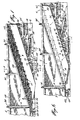
- the apparatus of the invention comprises an elongated table 1 having a rear portion 2 and a front portion 3 relative to the - direction of movement of the solid wood-laminated continuous panel A being made by the apparatus and consisting of'elongated wood blocks 8, of uniform size and glued together.
- the rear portion 2 of the horizontal table carries a ram member 4 and a triangular pressing plate 5, which has a front transverse edge 6.
- the front portion of the table carries over the same a glue-curing and pressing plate 7 having its rear edge terminated at the edge 6 of plate 5.
- Plate 7 is disposed in alignment with and forwardly of pressing plate 5.
- a braking plate B is arranged forwardly of the glue-curing plate 7 and in alignment therewith.
- Ram member 4 is in the form of an elongpted beam having a stepped forward edge 9 defined by a plurality of successive steps 10 extending transversely of the table and each equally spaced from the other longitudinally of the table, the imaginary line passing through the outer corners of each step 10 is straight and is inclined with respect to the table.
- the ram member 4 has an L-shaped cross-section, as shown in Figure 7, and is reinforced at its rear upstanding flange by a strip -11 while its horizontal flange is reinforced and made thicker by strips 12 and plate 13.
- the ram member slides on the table 1 in a reciprocating movement, being actuated by a double-acting hydraulic cylinder piston unit 15 pivotally connected at 16 to the rear edge of the ram member and at 17 to a bracket 18 fixed to the table.
- each guide member has a central angular slot 20 engaging a freely rotatable guide wheel 21, the shaft of which is secured to the top of table 1.
- the angular guides 19 are fixed at their free ends to reinforcing bars 22 and overlying bridging bars 22'. Bare 22 are fixed to the ram member 4.
- Each slot 20 has a forward portiorf 23 which is inclined with respect to the length of the table at about 30° while each slot 20 hae a rear portion 24 which is parallel to the longitudinal axis of the table 1.
- the outermost rear end portion 25 of the guiding slot 20 is curved to extend at a slight angle with respect to the long axis of the table 4.
- the forward end of the ram table forms a finger having a rounded end 26, which is engageable with a guide wheel 27 appropriately located and carried by the top of the table.
- a stacking rack assembly for holding a plurality of stacks of elongated solid wood blocks 8.
- the rack assembly 29 consists of upright angle irons 30 properly secured one to another and defining as many compartments as there are stacks of blocks B. These uprights are carried by beams 31, as shown in Figure 5, in turn secured to an operator's platform 32 overlying the ram member in its retracted position. Said operating platform 32 may be suspended from the room in which the device is located and is preferably provided with a handrail 33.
- the lower end of the angle irons 30 of the rack is spaced upwardly from the table 1 a distance slightly greater than the thickness of the wooden blocks B; so, upon forward movement of the ram momber 4 from its retracted position, as shown in Figure 5, the lowermost blocks B of each stack will be engaged by the ram member and pushed laterally away from the rack assembly 29, as shown in Figure 7, while the next lowermost series of blocks will rest on the ram member 4.
- Each rack of the rack assembly 29 holds a stack of blocks B in longitudinal alignment with the table and in staggered position one with respect to the other, so as to conform with the longitudinal spacing of the steps 10 of the operating edge of the ram membor 4.
- the pressing plate 5 is mounted for pivoting movement to uncover the portion of the table underneath the same. More particularly, it is pivotally carried at 34 to the ends of arms 35 which are pivoted intermediate their ends on brackets 36 carried by the table 1.
- the outer ends of the arms 35 are power-actuated by means of double-acting hydraulic cylinder and piston units 37 pivotally attached to said arms and to brackets 38 carried by the frame work 40 of the table 1.
- the hydraulic cylinder and piston units 37 serve also to press the pressing plate 5 against assembled wooden blocks B lying underneath and slidably supported by table 1.
- the glue-curing plate 7, shown in Figure 2 and also in cmss-section in Figure 3, is mounted for swinging movement so as to uncover the table portion lying underneath the same.
- the same arrangement of arms 35, brackets 36 and double-acting hydraulic cylinder and piston units 37 pivotally carried by brackets 38 are arranged for the glue-curing plate 7.
- the same can be applied with pressure against the wooden blocks underlying the same.
- the glue-curing plato 7 is provided with a flat electrode 41 coextensive with said plate 7 and fed with high-frequency electricity by means of a cable 42 connected to a high-frequency generator,generally indicated at 43 and of known construction.
- the braking plate 8 shown in Figures 2 and 4 also overlies the table and is secured to a frame 44 connected to double-acting hydraulic cylinder and piston units 45, which are in turn pivotally connected to a support 46 carried by the table 1. Cylinder units 45 can raise and lower the braking plate 8 to press the same against the assembled wooden panel, so as to exert a braking force resisting the forward movement of the panel under the forward pressure exerted by the ram member 4.
- the table 1 is provided along its longitudinal edge opposite to the ram member 4 with a guiding and abutment shoulder 47 upstanding therefrom, said shoulder 47 being shown in Figures 1, 2, 5, and 6. Downstream from guiding roller 27 on the same side as the ram member, there is also provided a guide member 48 extending longitudinally of the table and having a rounded end 49 adjacent the guide roller 27.
- the machine operates as follows:
- the braking member 8 axerts its braking force during the last two-thirds of the forward longitudinal stroke of the ram member.
- the end generator of the forward stroke of the ram member initiates the high-frequency to start the glue-curing cycle. Completion of the cycle initiates the backward stroke and the succeeding forward stroke of ram member 4.
- the assembled moving blocks B move step by step through the apparatus and the final laminated panel A is of continuous length and the glue is completely cured. Because of the lateral pressure exerted on the assembled blocks by the ram member and the longitudinal compression exerted by the ram mamber and the braking device 8, the longitudinal and transverse joints in panel 8 have a close and smooth fit.
- a cross saw may be installed close to the discharge end of the machine to cut off thebevelled leading end of the panel and to cut the latter into desired lengths.
- the blocks 8 are longitudinally aligned with respect, to the machine in several longitudinal rows, and the blocks B of each row are longitudinally offset with respect to the blocks of an adjacent row, prefably by about 1/3 of the length of an individual block.
Landscapes
- Engineering & Computer Science (AREA)
- Life Sciences & Earth Sciences (AREA)
- Manufacturing & Machinery (AREA)
- Wood Science & Technology (AREA)
- Forests & Forestry (AREA)
Priority Applications (3)
| Application Number | Priority Date | Filing Date | Title |
|---|---|---|---|
| CA000373166A CA1168968A (fr) | 1981-03-17 | 1981-03-17 | Installation et methode de production de panneaux continus en bois solide lamelle |
| US06/363,726 US4402781A (en) | 1981-03-17 | 1982-03-30 | Continuous solid wood laminated panels |
| EP83108646A EP0137858A2 (fr) | 1981-03-17 | 1983-09-02 | Dispositif et méthode de fabrication d'un panneau continu et revêtu de bois à partir des lamelles de bois |
Applications Claiming Priority (3)
| Application Number | Priority Date | Filing Date | Title |
|---|---|---|---|
| CA000373166A CA1168968A (fr) | 1981-03-17 | 1981-03-17 | Installation et methode de production de panneaux continus en bois solide lamelle |
| US06/363,726 US4402781A (en) | 1981-03-17 | 1982-03-30 | Continuous solid wood laminated panels |
| EP83108646A EP0137858A2 (fr) | 1981-03-17 | 1983-09-02 | Dispositif et méthode de fabrication d'un panneau continu et revêtu de bois à partir des lamelles de bois |
Publications (1)
| Publication Number | Publication Date |
|---|---|
| EP0137858A2 true EP0137858A2 (fr) | 1985-04-24 |
Family
ID=27167004
Family Applications (1)
| Application Number | Title | Priority Date | Filing Date |
|---|---|---|---|
| EP83108646A Withdrawn EP0137858A2 (fr) | 1981-03-17 | 1983-09-02 | Dispositif et méthode de fabrication d'un panneau continu et revêtu de bois à partir des lamelles de bois |
Country Status (3)
| Country | Link |
|---|---|
| US (1) | US4402781A (fr) |
| EP (1) | EP0137858A2 (fr) |
| CA (1) | CA1168968A (fr) |
Cited By (2)
| Publication number | Priority date | Publication date | Assignee | Title |
|---|---|---|---|---|
| EP0418487A3 (en) * | 1989-07-21 | 1991-09-11 | Flex Par K Corp. | Flooring panel manufacture |
| EP0496341A3 (en) * | 1991-01-19 | 1992-11-25 | Rainer Stepanek | Method and apparatus for the manufacture of parquet flooring |
Families Citing this family (5)
| Publication number | Priority date | Publication date | Assignee | Title |
|---|---|---|---|---|
| FR2576541B1 (fr) * | 1985-01-30 | 1988-07-08 | Henry Gerard | Procede et installation de fabrication en continu de lamelle-colle et produit issu de la mise en oeuvre de ce procede |
| US4960481A (en) * | 1987-05-08 | 1990-10-02 | Minnesota Mining And Manufacturing Company | Laminating method |
| FI82519B (fi) * | 1988-12-16 | 1990-11-30 | Partek Ab | Laongstraeckt lamellskiva av mineralull, laemplig som kaerna i ett sandwichelement. |
| FI82517B (fi) * | 1988-12-16 | 1990-11-30 | Partek Ab | Laongstraeckt lamellskiva av mineralull och foerfarande foer dess tillverkning. |
| CN101918184B (zh) * | 2007-09-28 | 2015-01-14 | Gaia木专利股份公司 | 用于处理木材的方法 |
Family Cites Families (5)
| Publication number | Priority date | Publication date | Assignee | Title |
|---|---|---|---|---|
| US2401648A (en) * | 1941-02-07 | 1946-06-04 | Kahr Gustaf | Means for manufacturing composite board structures |
| US2453185A (en) * | 1943-09-10 | 1948-11-09 | Steinway & Sons | Apparatus for edge-gluing strip elements |
| US2537918A (en) * | 1947-04-28 | 1951-01-09 | Per F Skoog | Core assembly machine |
| US2708649A (en) * | 1952-01-19 | 1955-05-17 | Jack B Cunningham | Method and apparatus for dielectric projection bonding of wood materials |
| US2642835A (en) * | 1952-04-25 | 1953-06-23 | Laminated Lumber Products Inc | Glue applying apparatus for lumber gluing machine |
-
1981
- 1981-03-17 CA CA000373166A patent/CA1168968A/fr not_active Expired
-
1982
- 1982-03-30 US US06/363,726 patent/US4402781A/en not_active Expired - Fee Related
-
1983
- 1983-09-02 EP EP83108646A patent/EP0137858A2/fr not_active Withdrawn
Cited By (2)
| Publication number | Priority date | Publication date | Assignee | Title |
|---|---|---|---|---|
| EP0418487A3 (en) * | 1989-07-21 | 1991-09-11 | Flex Par K Corp. | Flooring panel manufacture |
| EP0496341A3 (en) * | 1991-01-19 | 1992-11-25 | Rainer Stepanek | Method and apparatus for the manufacture of parquet flooring |
Also Published As
| Publication number | Publication date |
|---|---|
| CA1168968A (fr) | 1984-06-12 |
| US4402781A (en) | 1983-09-06 |
Similar Documents
| Publication | Publication Date | Title |
|---|---|---|
| US4128119A (en) | Apparatus for processing workpieces in the form of short-length elongate timber waste into usable timber | |
| CN103895073B (zh) | 一种拼板机 | |
| CN103817752B (zh) | 一种新型人造板热压与冷压可自动循环工作的联合机组设备 | |
| US4402781A (en) | Continuous solid wood laminated panels | |
| CN204997787U (zh) | 一种旋转式木工拼板机 | |
| CN108748461B (zh) | 拼板机 | |
| CN107214786B (zh) | 竹片的接长方法、竹片接长装置及应用 | |
| US3894908A (en) | I-beam type truss joist forming apparatus with automated web infeed | |
| CN111923168B (zh) | 一种木材拼凑自动生产线 | |
| CN110815435B (zh) | 一种木工移动接料和切料的方法 | |
| CN210210728U (zh) | 一种高效木皮切割装置 | |
| CN217992840U (zh) | 一种刨花板蒙皮涂覆装置 | |
| CN215149987U (zh) | 一种卧式数控木墩条板打钉机 | |
| US3998252A (en) | Wood slicing apparatus | |
| CN221160788U (zh) | 一种具有木料调节夹紧功能的旋切机 | |
| CN210477254U (zh) | 一种适用于全息烫印膜制版的拼板机 | |
| DE2024150A1 (de) | Bogen Geradleger | |
| CN219004407U (zh) | 串焊机的焊带加工装置 | |
| JPS6056501A (ja) | 木製合板製造方法および木製合板製造装置 | |
| CN112298999B (zh) | 一种夹层彩钢板生产装置 | |
| CN116929155A (zh) | 一种异型组合烟花的异型筒排成型装置 | |
| CN220547554U (zh) | 一种输电铁塔铁附件抱铁成形装置 | |
| CN222004461U (zh) | 一种自动包边推紧块装置 | |
| NO833171L (no) | Kontinuerlig laminerte heltresplater | |
| CN223719720U (zh) | 配拼板机板件自动摆放设备 |
Legal Events
| Date | Code | Title | Description |
|---|---|---|---|
| PUAI | Public reference made under article 153(3) epc to a published international application that has entered the european phase |
Free format text: ORIGINAL CODE: 0009012 |
|
| AK | Designated contracting states |
Designated state(s): AT BE CH DE FR GB IT LI LU NL SE |
|
| STAA | Information on the status of an ep patent application or granted ep patent |
Free format text: STATUS: THE APPLICATION IS DEEMED TO BE WITHDRAWN |
|
| 18D | Application deemed to be withdrawn |
Effective date: 19860708 |
|
| RIN1 | Information on inventor provided before grant (corrected) |
Inventor name: COUTURE, JOACHIM Inventor name: COUTURE, RAYMOND |