EP0137896A1 - Circuit pour compenser les variations du facteur de transfert d'une sonde linéaire de champ magnétique - Google Patents
Circuit pour compenser les variations du facteur de transfert d'une sonde linéaire de champ magnétique Download PDFInfo
- Publication number
- EP0137896A1 EP0137896A1 EP84104472A EP84104472A EP0137896A1 EP 0137896 A1 EP0137896 A1 EP 0137896A1 EP 84104472 A EP84104472 A EP 84104472A EP 84104472 A EP84104472 A EP 84104472A EP 0137896 A1 EP0137896 A1 EP 0137896A1
- Authority
- EP
- European Patent Office
- Prior art keywords
- magnetic field
- field sensor
- output
- current source
- current
- Prior art date
- Legal status (The legal status is an assumption and is not a legal conclusion. Google has not performed a legal analysis and makes no representation as to the accuracy of the status listed.)
- Granted
Links
- 230000005540 biological transmission Effects 0.000 title claims abstract description 15
- 238000009415 formwork Methods 0.000 claims 1
- 238000005259 measurement Methods 0.000 description 5
- 230000032683 aging Effects 0.000 description 3
- 239000004020 conductor Substances 0.000 description 3
- 230000008030 elimination Effects 0.000 description 2
- 238000003379 elimination reaction Methods 0.000 description 2
- 230000004907 flux Effects 0.000 description 2
- 238000006243 chemical reaction Methods 0.000 description 1
- 230000008878 coupling Effects 0.000 description 1
- 238000010168 coupling process Methods 0.000 description 1
- 238000005859 coupling reaction Methods 0.000 description 1
- 238000010586 diagram Methods 0.000 description 1
- 238000001914 filtration Methods 0.000 description 1
- 230000002452 interceptive effect Effects 0.000 description 1
- 239000004065 semiconductor Substances 0.000 description 1
- 230000035945 sensitivity Effects 0.000 description 1
Images
Classifications
-
- G—PHYSICS
- G01—MEASURING; TESTING
- G01R—MEASURING ELECTRIC VARIABLES; MEASURING MAGNETIC VARIABLES
- G01R33/00—Arrangements or instruments for measuring magnetic variables
- G01R33/02—Measuring direction or magnitude of magnetic fields or magnetic flux
Definitions
- the invention relates to a circuit arrangement for compensating for fluctuations in the transmission factor of a linear magnetic field sensor of the type mentioned in the preamble of claim 1.
- Magnetic field sensors are used to determine the strength of the magnetic field, e.g. Hall generators, magnetotransistors and other semiconductor elements that generate an output signal that is more or less proportional to the magnetic field.
- a magnetic counter field can be generated by means of a control loop and a magnetic coil, which practically completely compensates the magnetic field to be measured (DE-AS 26 21 302).
- the disadvantage of such so-called compensated transducers is the relatively high expenditure of power for generating the compensating magnetic field.
- Some of the known magnetic field sensors are characterized by a satisfactory linearity of the transmission characteristic, but the slope of the transmission characteristic is a function of the temperature and is also subject to changes due to aging. It is known (EP-A-00 18 750) to determine the slope of the transmission characteristic with a linear magnetic field sensor operating as a magnetic field / frequency converter with the aid of a magnetic direct field and to divide the output frequency by a frequency proportional to the slope, so that Fluctuations in the slope can be compensated.
- this type of determination of the slope presupposes that on the one hand the magnetic field to be measured is a pure alternating field and that on the other hand the transmission characteristic of the magnetic field sensor has no offset.
- the invention has for its object to equip a circuit arrangement of the type mentioned with a magnetic field / voltage converter as a magnetic field sensor and to design such that fluctuations in the gradient of the transmission characteristic of the magnetic field sensor due to temperature or aging influences can be properly compensated even if the magnetic field sensor is one Has offset voltage and if the magnetic field to be measured has a DC field component.
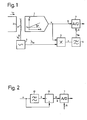
- 1 means a magnetic field sensor which is exposed to a magnetic field to be measured, outputs a voltage u at its output as a function of this magnetic field and thus works as a magnetic field / voltage converter.
- This magnetic field sensor 1 can be, for example, a Hall generator, a MOS magnetotransistor or a MOS magnetodiode.
- the slope a is a function of the temperature and is also subject to age-related fluctuations, so that despite the good linearity of the transmission characteristic curve, an exact measurement of the magnetic field is not possible without special measures.
- the magnetic field sensor 1 can be used to measure a measuring current flowing in an electrical conductor 2 in the magnetic field generated by it.
- the coupling of the generated by the measuring current i m th magnetic field in the magnetic field sensor 1 can take place in a known manner by means of a magnetic core or also without a magnetic core in that the magnetic field sensor 1 is arranged on the surface of the conductor 2 designed as a flat conductor.
- the current source 3 excites the solenoid 4 with an auxiliary current i h , which is an alternating current or a pulsating direct current.
- the magnetic coil 4 generates an alternating or pulsating auxiliary magnetic field of known size and with a known time profile. It is arranged so that this auxiliary field is superimposed on the magnetic field to be measured.
- the amplitude of the auxiliary field is a few percent of the maximum value of the amplitude of the magnetic field to be measured.
- the output of the magnetic field sensor 1 is connected to the signal input 8 of the analog / digital converter 7.
- the multiplier 5 has two inputs, one of which is connected to the output of the magnetic field sensor 1 and the other to the current source 3.
- the output of the multiplier 5 is connected to a reference voltage input 9 of the analog / digital converter 7 via the low pass 6.
- the DC component V dc of this product corresponds to the proportion of the output voltage produced solely by the auxiliary magnetic field is u and the slope a proportionally.
- the low p ass 6 passes the direct current component V dc of the signal v and blocks the remaining components thereof .
- the DC t s p o romkom component V dc reaches 7 as a reference voltage to the analog / digital converter, the sensitivity of the analog / digital converter 7 is proportional to the reciprocal of the reference voltage so that these transducers, the division respectively. carried out and the digital measurement result is independent of the slope a.
- the measuring device described is suitable for measuring alternating currents or alternating magnetic fields as well as direct currents or alternating magnetic fields.
- the time course of the auxiliary current i h is to be selected in such a way that correlations with the magnetic field to be measured are avoided.
- a sinusoidal auxiliary current i h with a frequency of a few kHz is suitable for measuring 50 Hz alternating fields.
- the current source 3 is particularly advantageous to design the current source 3 as a pseudo-random current source. If the time profile of the auxiliary current i h is rectangular, a polarity reversing switch can be used as the multiplier 5, which reverses the polarity of the output voltage u in time with the auxiliary current i h .
- the described compensation of fluctuations in the slope a ensures a high measurement accuracy and greatly reduces the requirements for the stability of the magnetic field sensor 1.
- the use of the analog / digital converter 7 as a division element results in a particularly simple circuit structure and eliminates the need for a stabilized DC voltage source for generating the reference voltage for this converter. Since the auxiliary magnetic field can be weak compared to the magnetic field to be measured, the generation of the auxiliary field requires a significantly lower expenditure of power compared to the compensated transducer mentioned at the beginning.
- a filter can be connected between the output of the magnetic field sensor 1 and the signal input 8 of the analog / digital converter 7, which blocks the DC current component contained in the output voltage u. This measure also eliminates the offset voltage u o of the magnetic field sensor 1.
- the filter mentioned advantageously consists of a low-pass element 10 and a subtractor element 11, the output of the magnetic field sensor 1 (FIG.
Landscapes
- Physics & Mathematics (AREA)
- Condensed Matter Physics & Semiconductors (AREA)
- General Physics & Mathematics (AREA)
- Measuring Magnetic Variables (AREA)
- Arrangements For Transmission Of Measured Signals (AREA)
- Measurement Of Current Or Voltage (AREA)
Priority Applications (1)
| Application Number | Priority Date | Filing Date | Title |
|---|---|---|---|
| AT84104472T ATE35867T1 (de) | 1983-08-08 | 1984-04-19 | Schaltungsanordnung zur kompensation von schwankungen des uebertragungsfaktors eines linearen magnetfeldsensors. |
Applications Claiming Priority (2)
| Application Number | Priority Date | Filing Date | Title |
|---|---|---|---|
| CH4448/83 | 1983-08-08 | ||
| CH4448/83A CH661359A5 (de) | 1983-08-08 | 1983-08-08 | Schaltungsanordnung zur kompensation von schwankungen des uebertragungsfaktors eines linearen magnetfeldsensors. |
Publications (2)
| Publication Number | Publication Date |
|---|---|
| EP0137896A1 true EP0137896A1 (fr) | 1985-04-24 |
| EP0137896B1 EP0137896B1 (fr) | 1988-07-20 |
Family
ID=4276311
Family Applications (1)
| Application Number | Title | Priority Date | Filing Date |
|---|---|---|---|
| EP84104472A Expired EP0137896B1 (fr) | 1983-08-08 | 1984-04-19 | Circuit pour compenser les variations du facteur de transfert d'une sonde linéaire de champ magnétique |
Country Status (4)
| Country | Link |
|---|---|
| EP (1) | EP0137896B1 (fr) |
| AT (1) | ATE35867T1 (fr) |
| CH (1) | CH661359A5 (fr) |
| DE (1) | DE3472840D1 (fr) |
Cited By (4)
| Publication number | Priority date | Publication date | Assignee | Title |
|---|---|---|---|---|
| US4752733A (en) * | 1984-08-16 | 1988-06-21 | Jan Petr | Compensating circuit for a magnetic field sensor |
| WO1997014976A1 (fr) * | 1995-10-18 | 1997-04-24 | Vdo Adolf Schindling Ag | Detecteur de champ magnetique |
| GB2312521A (en) * | 1996-04-23 | 1997-10-29 | Hughes Aircraft Co | Digital flux gate magnetometer |
| US6724184B1 (en) * | 1999-01-28 | 2004-04-20 | Robert Bosch Gmbh | Device and method for determining a magnetic field as to its intensity and direction |
Citations (4)
| Publication number | Priority date | Publication date | Assignee | Title |
|---|---|---|---|---|
| DE1297755B (de) * | 1963-05-10 | 1969-06-19 | Siemens Ag | Magnetfeldmessgeraet mit einer Sonde mit magnetfeldabhaengigem Widerstand |
| US4013946A (en) * | 1975-04-02 | 1977-03-22 | Harnessed Energies, Inc. | Means for determining a first magnetic field direction by measuring secondary magnetic fields induced in a body rotated in said first field |
| DE2719073B1 (de) * | 1977-04-29 | 1978-06-22 | Grundig Emv | Verfahren zur Erkennung der Induktion Null mittels einer Feldplatte |
| EP0018750A1 (fr) * | 1979-05-04 | 1980-11-12 | THE GENERAL ELECTRIC COMPANY, p.l.c. | Magnétomètres à domaines magnétiques |
-
1983
- 1983-08-08 CH CH4448/83A patent/CH661359A5/de not_active IP Right Cessation
-
1984
- 1984-04-19 EP EP84104472A patent/EP0137896B1/fr not_active Expired
- 1984-04-19 DE DE8484104472T patent/DE3472840D1/de not_active Expired
- 1984-04-19 AT AT84104472T patent/ATE35867T1/de not_active IP Right Cessation
Patent Citations (4)
| Publication number | Priority date | Publication date | Assignee | Title |
|---|---|---|---|---|
| DE1297755B (de) * | 1963-05-10 | 1969-06-19 | Siemens Ag | Magnetfeldmessgeraet mit einer Sonde mit magnetfeldabhaengigem Widerstand |
| US4013946A (en) * | 1975-04-02 | 1977-03-22 | Harnessed Energies, Inc. | Means for determining a first magnetic field direction by measuring secondary magnetic fields induced in a body rotated in said first field |
| DE2719073B1 (de) * | 1977-04-29 | 1978-06-22 | Grundig Emv | Verfahren zur Erkennung der Induktion Null mittels einer Feldplatte |
| EP0018750A1 (fr) * | 1979-05-04 | 1980-11-12 | THE GENERAL ELECTRIC COMPANY, p.l.c. | Magnétomètres à domaines magnétiques |
Cited By (7)
| Publication number | Priority date | Publication date | Assignee | Title |
|---|---|---|---|---|
| US4752733A (en) * | 1984-08-16 | 1988-06-21 | Jan Petr | Compensating circuit for a magnetic field sensor |
| AU587986B2 (en) * | 1984-08-16 | 1989-09-07 | Lgz Landis & Gyr Zug A.G. | Circuit arrangement for the compensation of fluctuations in the transmission factor of a magnetic field sensor |
| WO1997014976A1 (fr) * | 1995-10-18 | 1997-04-24 | Vdo Adolf Schindling Ag | Detecteur de champ magnetique |
| US6150811A (en) * | 1995-10-18 | 2000-11-21 | Mannesmann Vdo Ag | Magnetic field sensor for stable magnetic field measurement over a wide temperature range |
| GB2312521A (en) * | 1996-04-23 | 1997-10-29 | Hughes Aircraft Co | Digital flux gate magnetometer |
| GB2312521B (en) * | 1996-04-23 | 2000-12-06 | Hughes Aircraft Co | Digital flux gate magnetometer |
| US6724184B1 (en) * | 1999-01-28 | 2004-04-20 | Robert Bosch Gmbh | Device and method for determining a magnetic field as to its intensity and direction |
Also Published As
| Publication number | Publication date |
|---|---|
| DE3472840D1 (en) | 1988-08-25 |
| CH661359A5 (de) | 1987-07-15 |
| EP0137896B1 (fr) | 1988-07-20 |
| ATE35867T1 (de) | 1988-08-15 |
Similar Documents
| Publication | Publication Date | Title |
|---|---|---|
| EP0172402B1 (fr) | Circuit pour la compensation des fluctuations dans le facteur de transfert d'un capteur de champ magnétique | |
| DE2744845C3 (de) | Verfahren zur Kompensation der elektrochemischen Störgleichspannung bei der magnetisch-induktiven Durchflußmessung mit periodisch umgepoltem magnetischem Gleichfeld | |
| DE3133019C2 (fr) | ||
| DE69422222T2 (de) | Magnetisch-induktiver Durchflussmesser und dazu gehöriges Messprinzip | |
| DE2410407A1 (de) | Verfahren zur kompensation der elektrochemischen stoergleichspannung bei der induktiven durchflussmessung mit periodisch geschaltetem gleichfeld | |
| EP2666023A1 (fr) | Dispositif de mesure de courant | |
| DE3322942C2 (de) | Schaltung zur Messung der magnetischen Induktion mit einer Hall-Feldsonde | |
| DE3122168A1 (de) | Elektronischer wirkverbrauchszaehler | |
| DE3642771C2 (fr) | ||
| DE2837113C2 (fr) | ||
| DE10224354C1 (de) | Schaltungsanordnung und Verfahren zur Kompensation von Änderungen eines Übertragungsfaktors einer Magnetfeldsensoranordnung | |
| DE69333695T2 (de) | Schaltung zur Leistungsberechnung | |
| DE3832568A1 (de) | Schaltungsanordnung zur temperaturkompensation von kapazitiven druck- und differenzdrucksensoren | |
| DE69033966T2 (de) | Sender | |
| EP0137896B1 (fr) | Circuit pour compenser les variations du facteur de transfert d'une sonde linéaire de champ magnétique | |
| EP0329652B1 (fr) | Dispositif pour mesurer un champ magnetique constant ou variable dans le temps | |
| EP0250028B1 (fr) | Dispositif de montage pour la compensation de dérivés dépendants ou non de la température d'un capteur capacitif | |
| DE102007032300A1 (de) | Stromsensor zur Gleich- oder Wechselstrommessung | |
| DE10334517B4 (de) | Messgerät für elektrische Energie für ein Wechselstromnetz | |
| DE102004056384A1 (de) | Verfahren zur Offseteliminierung aus Signalen magnetoresistiver Sensoren | |
| DE2827267C2 (de) | Restspannungs-Regelschaltung für ein Hall-Element | |
| DE102019120666B3 (de) | Sensorvorrichtung zur breitbandigen Messung von elektrischen Strömen durch einen Leiter und Verfahren zur breitbandigen Messung | |
| EP0438637A1 (fr) | Procédé et dispositif pour la détection de la valeur effective Ieff d'un courant à mesurer utilisant un élément Hall et un circuit d'amplification | |
| DE3143669C2 (de) | Schaltung zum Messen des Effektivwertes einer Wechselspannung | |
| DE3613991A1 (de) | Gleichstrommesswandler insbesondere fuer kleine messstroeme |
Legal Events
| Date | Code | Title | Description |
|---|---|---|---|
| PUAI | Public reference made under article 153(3) epc to a published international application that has entered the european phase |
Free format text: ORIGINAL CODE: 0009012 |
|
| AK | Designated contracting states |
Designated state(s): AT DE FR GB NL SE |
|
| 17P | Request for examination filed |
Effective date: 19850518 |
|
| 17Q | First examination report despatched |
Effective date: 19861030 |
|
| GRAA | (expected) grant |
Free format text: ORIGINAL CODE: 0009210 |
|
| AK | Designated contracting states |
Kind code of ref document: B1 Designated state(s): AT DE FR GB NL SE |
|
| REF | Corresponds to: |
Ref document number: 35867 Country of ref document: AT Date of ref document: 19880815 Kind code of ref document: T |
|
| GBT | Gb: translation of ep patent filed (gb section 77(6)(a)/1977) | ||
| REF | Corresponds to: |
Ref document number: 3472840 Country of ref document: DE Date of ref document: 19880825 |
|
| ET | Fr: translation filed | ||
| PLBE | No opposition filed within time limit |
Free format text: ORIGINAL CODE: 0009261 |
|
| STAA | Information on the status of an ep patent application or granted ep patent |
Free format text: STATUS: NO OPPOSITION FILED WITHIN TIME LIMIT |
|
| 26N | No opposition filed | ||
| PGFP | Annual fee paid to national office [announced via postgrant information from national office to epo] |
Ref country code: GB Payment date: 19900331 Year of fee payment: 7 |
|
| PGFP | Annual fee paid to national office [announced via postgrant information from national office to epo] |
Ref country code: FR Payment date: 19900407 Year of fee payment: 7 |
|
| PGFP | Annual fee paid to national office [announced via postgrant information from national office to epo] |
Ref country code: AT Payment date: 19900411 Year of fee payment: 7 |
|
| PGFP | Annual fee paid to national office [announced via postgrant information from national office to epo] |
Ref country code: SE Payment date: 19900420 Year of fee payment: 7 |
|
| PGFP | Annual fee paid to national office [announced via postgrant information from national office to epo] |
Ref country code: NL Payment date: 19900430 Year of fee payment: 7 |
|
| PGFP | Annual fee paid to national office [announced via postgrant information from national office to epo] |
Ref country code: DE Payment date: 19900502 Year of fee payment: 7 |
|
| PG25 | Lapsed in a contracting state [announced via postgrant information from national office to epo] |
Ref country code: GB Effective date: 19910419 Ref country code: AT Effective date: 19910419 |
|
| PG25 | Lapsed in a contracting state [announced via postgrant information from national office to epo] |
Ref country code: SE Effective date: 19910420 |
|
| PG25 | Lapsed in a contracting state [announced via postgrant information from national office to epo] |
Ref country code: NL Effective date: 19911101 |
|
| NLV4 | Nl: lapsed or anulled due to non-payment of the annual fee | ||
| GBPC | Gb: european patent ceased through non-payment of renewal fee | ||
| PG25 | Lapsed in a contracting state [announced via postgrant information from national office to epo] |
Ref country code: FR Effective date: 19911230 |
|
| PG25 | Lapsed in a contracting state [announced via postgrant information from national office to epo] |
Ref country code: DE Effective date: 19920201 |
|
| REG | Reference to a national code |
Ref country code: FR Ref legal event code: ST |
|
| EUG | Se: european patent has lapsed |
Ref document number: 84104472.0 Effective date: 19911108 |