EP0137958A2 - Charge propulsive et son procédé de fabrication - Google Patents
Charge propulsive et son procédé de fabrication Download PDFInfo
- Publication number
- EP0137958A2 EP0137958A2 EP84109753A EP84109753A EP0137958A2 EP 0137958 A2 EP0137958 A2 EP 0137958A2 EP 84109753 A EP84109753 A EP 84109753A EP 84109753 A EP84109753 A EP 84109753A EP 0137958 A2 EP0137958 A2 EP 0137958A2
- Authority
- EP
- European Patent Office
- Prior art keywords
- propellant charge
- propellant
- sleeve
- mass
- powder
- Prior art date
- Legal status (The legal status is an assumption and is not a legal conclusion. Google has not performed a legal analysis and makes no representation as to the accuracy of the status listed.)
- Granted
Links
Images


Classifications
-
- C—CHEMISTRY; METALLURGY
- C06—EXPLOSIVES; MATCHES
- C06B—EXPLOSIVES OR THERMIC COMPOSITIONS; MANUFACTURE THEREOF; USE OF SINGLE SUBSTANCES AS EXPLOSIVES
- C06B21/00—Apparatus or methods for working-up explosives, e.g. forming, cutting, drying
- C06B21/0033—Shaping the mixture
- C06B21/0041—Shaping the mixture by compression
-
- F—MECHANICAL ENGINEERING; LIGHTING; HEATING; WEAPONS; BLASTING
- F42—AMMUNITION; BLASTING
- F42B—EXPLOSIVE CHARGES, e.g. FOR BLASTING, FIREWORKS, AMMUNITION
- F42B5/00—Cartridge ammunition, e.g. separately-loaded propellant charges
- F42B5/02—Cartridges, i.e. cases with charge and missile
- F42B5/16—Cartridges, i.e. cases with charge and missile characterised by composition or physical dimensions or form of propellant charge, with or without projectile, or powder
Definitions
- the invention relates to a propellant charge according to claim 1 and a method for its production.
- the propellant charge powder bodies are compressed in the propellant charge sleeve by applying external pressure and without the addition of binding agents and / or solvents to a charge density of between 1.0 and 1.5 g / cm and are elastically or plastically deformed with an almost uniform or gradually different compression , wherein portions with the same or different pressures are compressed in sections uniformly or gradually differently in the propellant charge sleeve.
- the measures described there are aimed, in particular, at increasing the mass to be accommodated in a given propellant charge sleeve by compressing the entire propellant, possibly in partial quantities.
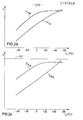
- the object of the invention and its solution is directed to a propellant charge with a structure by which in the upper operating temperature range the increase de.s during the development of the shot maximum gas pressure can be influenced with increasing temperature until it is eliminated.
- the starting point is a propellant charge powder for which a p, T curve according to the above-mentioned diagram exists in the case of loose bulk and without binding agent and / or solvent, and in a first example from a corresponding total mass N of the propellant charge.
- a first portion of preferably about 50 to 80% is at least partially compressed. This will be discussed in more detail later.
- the above-mentioned pressure increase can advantageously be influenced with increasing temperature until it is eliminated.
- the increase in performance consists in the possible Bombardment of a weapon barrel, which is designed for a certain maximum gas pressure, with a propellant charge that would no longer be permissible if the propellant powder was poured loose due to the steep rise in the p, T curve at higher operating temperatures.
- the effective area of a press ram for compression can correspond to the clear internal cross section of the propellant charge sleeve, and the first portion can be compressed overall.
- the propellant charge is to be incorporated according to the invention of an at least partially combustible propellant charge sleeve - this can apply to ammunition in the caliber range below 20 mm to over 120 mm - it is advisable to compress the first portion in a comparatively smooth-walled device for which the pressure load when compressing the first share is designed. From this device, the compressed - possibly, as in the case of the bottle sleeve, only partially compressed - the first portion can be transferred to the aforementioned propellant charge sleeve by axial pressing. In order to avoid disadvantageous wall friction, a thin-walled tube can be arranged in the propellant charge sleeve before being transferred and then removed again.
- a curve Sp N in FIG. 1 a illustrates the behavior of a propellant charge from a propellant charge loosely poured into a propellant charge sleeve.
- the curve in question shows that in the upper service temperature range a horizontal limit Gl, which indicates the mean maximum permissible gas pressure for a first weapon barrel, is exceeded by the curve Sp n in the steep slope (dashed part). The propellant charge is therefore unsuitable for the relevant temperature range.
- a curve S vN is plotted in FIG. 1b for the loose propellant charge.
- a curve E pN in FIG. 1 a shows the behavior of a propellant charge according to the invention, the mass N of which corresponds to that of the loosely poured propellant charge.
- the two corresponding curves E pM and E vM characterize the behavior of a propellant charge according to the invention, the mass M of which is greater than that of the bulk propellant charge known from FIGS. 1 a and 1 b (mass N).
- the same propellant charge sleeve and the same propellant charge powder are again assumed.
- the propellant charge of loose fill can now be used, but from the course of the curves E pM and E VM for the propellant charge according to the invention, the interior ballistic performance increase in the conventional sense mentioned above compared to the propellant charge of loose fill is clearly recognizable.
- a modified but similar course of the curves E pM and E vM can be achieved when using different propellant powders.
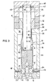
- FIG. 3 shows a device VI for carrying out the method according to the invention in a bottle-shaped propellant charge sleeve 10 with a sleeve wall 11 and a sleeve base 12.
- a threaded bore 14 is provided for a propellant charge lighter.
- the propellant charge sleeve 10 ends at the top in a sleeve neck 16.
- the device V1 consists of a thick-walled circular-cylindrical tube 18 with an inner flange 19 on the top side.
- a bottom piece 20 engages on the underside in the tube 18 and, in addition to a central axial receiving bore 22, has horizontal locking bores 21. The latter correspond to locking bores 18 'in the tube 18.
- the propellant charge sleeve 10 is received on the bottom side in the base piece 20, with fixing means 23 engaging through the bores 18' and 21 in an extraction groove 24 on the sleeve bottom side.
- the propellant charge sleeve 10 has first been inserted with the base piece 20 in the direction of an arrow 54 into the tube 18, aligned with the central longitudinal axis A.
- the sleeve neck 16 is located in the area of a coaxial circular opening 26 in the inner flange 19.
- a funnel 28 is placed on an unspecified top surface of the inner flange 19 and is surrounded by two spacer rings 30 and 32 in the case shown.
- a circular cylindrical press die 34 with a press surface 38 on the underside has a fixing groove 36 in the upper free end. With the latter, the press die 34 is received in a holder 40 with radial bores 42. Only indicated fixing means 43 in the bores 42 engage in the groove 36 and fix the press ram 34 in the holder 40.
- a first portion of a propellant charge is poured in the form of loose bulk powder through the funnel 28. This first part is about 50 to about 80% of the total mass of the propellant to be incorporated.
- the holder 40 is moved in the direction of an arrow 52 with the press ram 34 fixed therein, with the application of a predetermined pressure.
- the pressing surface 38 comes into contact with a surface of the bed, not shown, and a part 46 of the first portion 44 is compressed. Since the outer diameter of the press ram 34 is smaller than the clear inner diameter of the propellant charge sleeve 10 in the region of its wall 11, an annular cylindrical cavity 48 remains, in which a small amount 50 of uncompacted propellant charge powder remains.
- a dummy body 15 is arranged in the threaded bore 14 for the propellant charge lighter and in the receiving bore 22 of the base piece 20.
- the part of the dummy body 15 protruding into the interior of the propellant charge sleeve 10, which is not described in any more detail, is essentially the same dimension as the propellant charge lighter. Therefore, after removing the dummy body 15, the propellant charge lighter can easily be inserted into a channel 15 'which remains in the compressed part 46 after removing the dummy body 15.
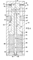
- Fig. 4 shows a device V2 with a circular cylindrical tube 60 of sufficient wall thickness in which a bottom piece 62 is inserted on the underside.
- the latter has a central axial threaded bore 64 for receiving a dummy body 66.
- a press ram 68 the outside diameter of which corresponds to the inside diameter of the tube 60, has a pressing surface 70 on the underside and a rear actuating rod 72.
- a central axial bore 72 ′ creates an interior space 73 that extends into a free upper end 75 of the rod 72. Vent holes 74 'connect the interior 73 with the surrounding atmosphere.
- Radial bores 79 are provided in a holder 76.
- Bolt-shaped fixing means 68 grip through these and fix the press ram 68 with its rod 72 in the holder 76 via recesses 75 '.
- a spacer ring 80 has a central opening 80 'which is adapted to the outer diameter of the rod 72.
- the spacer ring 80 lies with a flat underside surface 81 ′ on an upper-side flat circular ring surface 61 of the tube 60.
- the spacer ring 80 After the spacer ring 80 has been pushed over, it is fixed in the holder 76 and moved in the direction of an arrow 82 along a central longitudinal axis A while applying pressure against the loose powder filling of the first portion of the propellant charge.
- the dummy body 66 projecting over a top surface 63 of the base piece 62 corresponds essentially to the dimensions of a propellant charge lighter.
- the ram 68 moves downward, its free end 67 gets into the bore 72 ', the air being able to escape from the interior 73 through the ventilation bores 74'.
- the first portion 86 of the propellant charge is compressed as soon as the receptacle 76 with its underside circular ring surface 77 touches the top surface 81 of the spacer ring 80.
- the propellant charge is to be incorporated in a circular cylindrical inner cross section, not shown, of a metallic propellant charge sleeve, it can be provided with the dummy body 66, into which the tube 60, which is adapted to the outside diameter of the propellant charge sleeve, is inserted from below from its inside diameter; in this case, the outer diameter of the ram 68 must be adapted to the clear inner diameter of the metallic propellant charge sleeve, not shown.
- the press ram 34 has a central axial bore for the longer dummy body and then, if appropriate, also has a vent hole as in the device V2 in FIG. 4 must be provided.
- the spacer rings 30, 32 and 80 are interchangeable, so that the penetration depth of the press ram 34 or 68 can be changed to achieve a predetermined compression of the respective first portion 44 or 86 of the propellant charge.
Landscapes
- Engineering & Computer Science (AREA)
- General Engineering & Computer Science (AREA)
- Chemical & Material Sciences (AREA)
- Organic Chemistry (AREA)
- Portable Nailing Machines And Staplers (AREA)
- Containers And Packaging Bodies Having A Special Means To Remove Contents (AREA)
- Photoreceptors In Electrophotography (AREA)
- Medicinal Preparation (AREA)
- Drilling And Exploitation, And Mining Machines And Methods (AREA)
- Particle Formation And Scattering Control In Inkjet Printers (AREA)
- Golf Clubs (AREA)
Applications Claiming Priority (2)
| Application Number | Priority Date | Filing Date | Title |
|---|---|---|---|
| DE19833335821 DE3335821A1 (de) | 1983-10-01 | 1983-10-01 | Treibladung und verfahren zu ihrer herstellung |
| DE3335821 | 1983-10-01 |
Publications (4)
| Publication Number | Publication Date |
|---|---|
| EP0137958A2 true EP0137958A2 (fr) | 1985-04-24 |
| EP0137958A3 EP0137958A3 (en) | 1986-10-08 |
| EP0137958B1 EP0137958B1 (fr) | 1988-06-22 |
| EP0137958B2 EP0137958B2 (fr) | 1991-12-18 |
Family
ID=6210777
Family Applications (1)
| Application Number | Title | Priority Date | Filing Date |
|---|---|---|---|
| EP84109753A Expired - Lifetime EP0137958B2 (fr) | 1983-10-01 | 1984-08-16 | Charge propulsive et son procédé de fabrication |
Country Status (6)
| Country | Link |
|---|---|
| US (1) | US4625648A (fr) |
| EP (1) | EP0137958B2 (fr) |
| JP (1) | JPS6090889A (fr) |
| DE (2) | DE3335821A1 (fr) |
| ES (1) | ES536308A0 (fr) |
| NO (1) | NO843589L (fr) |
Cited By (3)
| Publication number | Priority date | Publication date | Assignee | Title |
|---|---|---|---|---|
| EP0429753A1 (fr) * | 1989-11-28 | 1991-06-05 | Rheinmetall GmbH | Procédé et dispositif pour la fabrication de munition de gros calibre |
| DE4138269A1 (de) * | 1991-11-21 | 1993-05-27 | Rheinmetall Gmbh | Munition |
| RU2139488C1 (ru) * | 1997-11-25 | 1999-10-10 | Конструкторское бюро приборостроения | Пороховой метательный заряд и способ его изготовления |
Families Citing this family (9)
| Publication number | Priority date | Publication date | Assignee | Title |
|---|---|---|---|---|
| DE3523930A1 (de) * | 1985-07-04 | 1987-01-08 | Dynamit Nobel Ag | Schutzverfahren beim umhuellen von temperatur- bzw. druckempfindlichen stoffen |
| US4823699A (en) * | 1987-04-14 | 1989-04-25 | Aai Corporation | Back-actuated forward ignition ammunition and method |
| US5272828A (en) * | 1992-08-03 | 1993-12-28 | Colt's Manufacturing Company Inc. | Combined cartridge magazine and power supply for a firearm |
| US5301448A (en) * | 1992-09-15 | 1994-04-12 | Colt's Manufacturing Company Inc. | Firearm safety system |
| US5421264A (en) * | 1992-09-15 | 1995-06-06 | Colt's Manufacturing Company Inc. | Firearm cartridge with pre-pressurizing charge |
| FR2746054B1 (fr) * | 1996-03-13 | 1998-06-12 | Procede, moyens et dispositif de compactage, adaptes au compactage de matieres a tendance pyrophorique | |
| US20150268022A1 (en) * | 2014-03-23 | 2015-09-24 | Blake Van Brouwer | Channel-forming propellant compression die and method |
| EP3721163B1 (fr) | 2017-12-08 | 2023-08-02 | Rabuffo SA | Cartouche de munition |
| US12264903B2 (en) | 2017-12-08 | 2025-04-01 | Rabuffo Sa | Ammunition cartridge |
Family Cites Families (14)
| Publication number | Priority date | Publication date | Assignee | Title |
|---|---|---|---|---|
| BE381075A (fr) * | 1931-04-29 | |||
| US2275569A (en) * | 1941-04-30 | 1942-03-10 | Trojan Powder Co | Loading pasty solids |
| US3078799A (en) * | 1960-09-29 | 1963-02-26 | Kabik Irving | Delay system |
| DE1261791B (de) * | 1963-02-13 | 1968-02-22 | Schermuly Pistol Rocket Appara | Verfahren zum Verpressen von pyrotechnischen Zusammensetzungen in einem glattwandigen Behaelter |
| US3390210A (en) * | 1965-07-16 | 1968-06-25 | Army Usa | Solventless extrusion process for forming rocket propellant grains |
| DE1796082B1 (de) * | 1968-08-28 | 1971-12-09 | Wasagchemie Ag | Zuender fuer die punktfoermige Initiierung von Sprengladungen |
| DE2035851C3 (de) * | 1970-07-18 | 1979-03-15 | Dynamit Nobel Ag, 5210 Troisdorf | Treibladungs-Pulverkörper und Verfahren zu seiner Herstellung |
| DE2239281C3 (de) * | 1972-08-10 | 1984-05-30 | Dynamit Nobel Ag, 5210 Troisdorf | Verfahren zur Herstellung von mit einer Hülle umgebenen Sprengstoffkörpern |
| CH579549A5 (fr) * | 1973-01-18 | 1976-09-15 | Ciba Geigy Ag | |
| CA1052179A (fr) * | 1973-01-24 | 1979-04-10 | Hercules Incorporated | Munitions sous enveloppes |
| US3999484A (en) * | 1975-10-28 | 1976-12-28 | Ici United States Inc. | Delay device having dimpled transfer disc |
| US4450768A (en) * | 1981-01-12 | 1984-05-29 | Schlumberger Technical Corporation | Shaped charge and method of making it |
| US4429632A (en) * | 1981-04-27 | 1984-02-07 | E. I. Du Pont De Nemours & Co. | Delay detonator |
| DE3205152C2 (de) * | 1982-02-13 | 1984-04-12 | Mauser-Werke Oberndorf Gmbh, 7238 Oberndorf | Treibladung für Hülsenmunition und Verfahren zu ihrer Herstellung |
-
1983
- 1983-10-01 DE DE19833335821 patent/DE3335821A1/de not_active Ceased
-
1984
- 1984-08-16 EP EP84109753A patent/EP0137958B2/fr not_active Expired - Lifetime
- 1984-08-16 DE DE8484109753T patent/DE3472294D1/de not_active Expired
- 1984-09-11 NO NO843589A patent/NO843589L/no unknown
- 1984-09-27 ES ES536308A patent/ES536308A0/es active Granted
- 1984-09-28 US US06/656,036 patent/US4625648A/en not_active Expired - Lifetime
- 1984-09-29 JP JP59203028A patent/JPS6090889A/ja active Granted
Cited By (4)
| Publication number | Priority date | Publication date | Assignee | Title |
|---|---|---|---|---|
| EP0429753A1 (fr) * | 1989-11-28 | 1991-06-05 | Rheinmetall GmbH | Procédé et dispositif pour la fabrication de munition de gros calibre |
| DE4138269A1 (de) * | 1991-11-21 | 1993-05-27 | Rheinmetall Gmbh | Munition |
| DE4138269C2 (de) * | 1991-11-21 | 1998-01-15 | Rheinmetall Ind Ag | Munition |
| RU2139488C1 (ru) * | 1997-11-25 | 1999-10-10 | Конструкторское бюро приборостроения | Пороховой метательный заряд и способ его изготовления |
Also Published As
| Publication number | Publication date |
|---|---|
| DE3335821A1 (de) | 1985-04-11 |
| EP0137958B1 (fr) | 1988-06-22 |
| NO843589L (no) | 1985-04-02 |
| JPS6090889A (ja) | 1985-05-22 |
| EP0137958A3 (en) | 1986-10-08 |
| ES8505907A1 (es) | 1985-07-01 |
| EP0137958B2 (fr) | 1991-12-18 |
| DE3472294D1 (en) | 1988-07-28 |
| ES536308A0 (es) | 1985-07-01 |
| US4625648A (en) | 1986-12-02 |
| JPH0445755B2 (fr) | 1992-07-27 |
Similar Documents
| Publication | Publication Date | Title |
|---|---|---|
| DE19944375A1 (de) | Hülsenboden für großkalibrige Munition | |
| EP0137958B2 (fr) | Charge propulsive et son procédé de fabrication | |
| EP0429753B1 (fr) | Procédé et dispositif pour la fabrication de munition de gros calibre | |
| EP0243578A1 (fr) | Procédé pour la fabrication d'une bague de palier à roulement comprenant un joint éclaté continu en au moins un endroit de sa périphérie | |
| EP2225477A2 (fr) | Procédé de remplissage d'un roulement à billes avec des corps de roulement, et roulement à billes rempli suivant ce procédé | |
| DE2143605A1 (de) | Patrone und Verfahren zu deren Her stellung | |
| DE3888288T2 (de) | Treibladung für flügelstabilisierte Geschossmunition sowie Verfahren zu ihrer Herstellung. | |
| EP0590188A1 (fr) | Outil de presse | |
| DE3506091A1 (de) | Verfahren und vorrichtung zum herstellen von treibladungen in patronenform fuer rohrwaffen | |
| CH688945A5 (de) | Verfahren zum Verschliessen des vorderen Huelsenkoerpers einer Manoeverpatrone. | |
| DD140847A5 (de) | Vorrichtung zum abstrecken und abstreifen einteiliger behaelterruempfe | |
| DE4420505C1 (de) | Verfahren zur Herstellung eines Jagdgeschosses mit Hohlspitze | |
| EP0106411A2 (fr) | Munition de petit calibre et son procédé de fabrication | |
| AT406088B (de) | Mantel-deformationsgeschoss | |
| DE3223777A1 (de) | Speichermasse fuer einen druckgasbehaelter | |
| DE1961923B2 (de) | Zusammengesetztes, hohen Temperaturen standhaltendes Gaswechselventil für Kraft- oder Arbeitsmaschinen, insbesondere Brennkraftmaschinen, sowie Verfahren zur Herstellung eines derartigen Ventils | |
| DE2248658A1 (de) | Verfahren zur herstellung von hartkerngeschossen | |
| DE2731333C2 (fr) | ||
| DE2943484C2 (de) | Verfahren zum Behandeln von gepreßten Hochbrisanz-Sprengstofformkörpern und Einrichtung sowie Werkzeug zur Durchführung des Verfahrens | |
| AT373689B (de) | Schiessgeraet, bestehend aus einem geschoss und einer abschussvorrichtung fuer dieses geschoss | |
| DE4012748C1 (fr) | ||
| DE3210128A1 (de) | Laufkammer fuer ein geschuetz | |
| DE2638770B2 (de) | Getter-Halterung für eine Kathodenstrahlröhre sowie Verfahren zum Einführen des Getterbehälters in den Kolben einer Kathodenstrahlröhre | |
| DE2310361A1 (de) | Plastikpfropfen fuer schrotpatronen | |
| DE10338184A1 (de) | Mörsergranate |
Legal Events
| Date | Code | Title | Description |
|---|---|---|---|
| PUAI | Public reference made under article 153(3) epc to a published international application that has entered the european phase |
Free format text: ORIGINAL CODE: 0009012 |
|
| AK | Designated contracting states |
Designated state(s): BE CH DE FR GB IT LI NL SE |
|
| PUAL | Search report despatched |
Free format text: ORIGINAL CODE: 0009013 |
|
| AK | Designated contracting states |
Kind code of ref document: A3 Designated state(s): BE CH DE FR GB IT LI NL SE |
|
| 17P | Request for examination filed |
Effective date: 19860903 |
|
| 17Q | First examination report despatched |
Effective date: 19870605 |
|
| ITF | It: translation for a ep patent filed | ||
| GRAA | (expected) grant |
Free format text: ORIGINAL CODE: 0009210 |
|
| AK | Designated contracting states |
Kind code of ref document: B1 Designated state(s): BE CH DE FR GB IT LI NL SE |
|
| GBT | Gb: translation of ep patent filed (gb section 77(6)(a)/1977) | ||
| REF | Corresponds to: |
Ref document number: 3472294 Country of ref document: DE Date of ref document: 19880728 |
|
| ET | Fr: translation filed | ||
| PLBI | Opposition filed |
Free format text: ORIGINAL CODE: 0009260 |
|
| 26 | Opposition filed |
Opponent name: MAUSER-WERKE OBERNDORF GMBH Effective date: 19890321 |
|
| NLR1 | Nl: opposition has been filed with the epo |
Opponent name: MAUSER-WERKE OBERNDORF GMBH |
|
| PGFP | Annual fee paid to national office [announced via postgrant information from national office to epo] |
Ref country code: BE Payment date: 19900727 Year of fee payment: 7 |
|
| ITTA | It: last paid annual fee | ||
| PG25 | Lapsed in a contracting state [announced via postgrant information from national office to epo] |
Ref country code: BE Effective date: 19910831 |
|
| PUAH | Patent maintained in amended form |
Free format text: ORIGINAL CODE: 0009272 |
|
| STAA | Information on the status of an ep patent application or granted ep patent |
Free format text: STATUS: PATENT MAINTAINED AS AMENDED |
|
| 27A | Patent maintained in amended form |
Effective date: 19911218 |
|
| AK | Designated contracting states |
Kind code of ref document: B2 Designated state(s): BE CH DE FR GB IT LI NL SE |
|
| REG | Reference to a national code |
Ref country code: CH Ref legal event code: AEN |
|
| GBTA | Gb: translation of amended ep patent filed (gb section 77(6)(b)/1977) | ||
| BERE | Be: lapsed |
Owner name: RHEINMETALL G.M.B.H. Effective date: 19910831 |
|
| NLR2 | Nl: decision of opposition | ||
| NLR3 | Nl: receipt of modified translations in the netherlands language after an opposition procedure | ||
| ET3 | Fr: translation filed ** decision concerning opposition | ||
| PGFP | Annual fee paid to national office [announced via postgrant information from national office to epo] |
Ref country code: SE Payment date: 19930713 Year of fee payment: 10 |
|
| PGFP | Annual fee paid to national office [announced via postgrant information from national office to epo] |
Ref country code: NL Payment date: 19930831 Year of fee payment: 10 |
|
| PG25 | Lapsed in a contracting state [announced via postgrant information from national office to epo] |
Ref country code: SE Effective date: 19940817 |
|
| EAL | Se: european patent in force in sweden |
Ref document number: 84109753.8 |
|
| PG25 | Lapsed in a contracting state [announced via postgrant information from national office to epo] |
Ref country code: NL Effective date: 19950301 |
|
| NLV4 | Nl: lapsed or anulled due to non-payment of the annual fee | ||
| EUG | Se: european patent has lapsed |
Ref document number: 84109753.8 |
|
| PGFP | Annual fee paid to national office [announced via postgrant information from national office to epo] |
Ref country code: GB Payment date: 19990713 Year of fee payment: 16 |
|
| PGFP | Annual fee paid to national office [announced via postgrant information from national office to epo] |
Ref country code: CH Payment date: 19990719 Year of fee payment: 16 |
|
| PGFP | Annual fee paid to national office [announced via postgrant information from national office to epo] |
Ref country code: FR Payment date: 19990722 Year of fee payment: 16 Ref country code: DE Payment date: 19990722 Year of fee payment: 16 |
|
| PG25 | Lapsed in a contracting state [announced via postgrant information from national office to epo] |
Ref country code: GB Free format text: LAPSE BECAUSE OF NON-PAYMENT OF DUE FEES Effective date: 20000816 |
|
| PG25 | Lapsed in a contracting state [announced via postgrant information from national office to epo] |
Ref country code: LI Free format text: LAPSE BECAUSE OF NON-PAYMENT OF DUE FEES Effective date: 20000831 Ref country code: CH Free format text: LAPSE BECAUSE OF NON-PAYMENT OF DUE FEES Effective date: 20000831 |
|
| GBPC | Gb: european patent ceased through non-payment of renewal fee |
Effective date: 20000816 |
|
| REG | Reference to a national code |
Ref country code: CH Ref legal event code: PL |
|
| PG25 | Lapsed in a contracting state [announced via postgrant information from national office to epo] |
Ref country code: FR Free format text: LAPSE BECAUSE OF NON-PAYMENT OF DUE FEES Effective date: 20010430 |
|
| PG25 | Lapsed in a contracting state [announced via postgrant information from national office to epo] |
Ref country code: DE Free format text: LAPSE BECAUSE OF NON-PAYMENT OF DUE FEES Effective date: 20010501 |
|
| REG | Reference to a national code |
Ref country code: FR Ref legal event code: ST |