EP0138112A2 - Support pour ponceuse à bande portable - Google Patents
Support pour ponceuse à bande portable Download PDFInfo
- Publication number
- EP0138112A2 EP0138112A2 EP84111444A EP84111444A EP0138112A2 EP 0138112 A2 EP0138112 A2 EP 0138112A2 EP 84111444 A EP84111444 A EP 84111444A EP 84111444 A EP84111444 A EP 84111444A EP 0138112 A2 EP0138112 A2 EP 0138112A2
- Authority
- EP
- European Patent Office
- Prior art keywords
- work table
- plate
- base plate
- belt
- base
- Prior art date
- Legal status (The legal status is an assumption and is not a legal conclusion. Google has not performed a legal analysis and makes no representation as to the accuracy of the status listed.)
- Withdrawn
Links
Images

Classifications
-
- B—PERFORMING OPERATIONS; TRANSPORTING
- B25—HAND TOOLS; PORTABLE POWER-DRIVEN TOOLS; MANIPULATORS
- B25H—WORKSHOP EQUIPMENT, e.g. FOR MARKING-OUT WORK; STORAGE MEANS FOR WORKSHOPS
- B25H1/00—Work benches; Portable stands or supports for positioning portable tools or work to be operated on thereby
- B25H1/0021—Stands, supports or guiding devices for positioning portable tools or for securing them to the work
-
- B—PERFORMING OPERATIONS; TRANSPORTING
- B24—GRINDING; POLISHING
- B24B—MACHINES, DEVICES, OR PROCESSES FOR GRINDING OR POLISHING; DRESSING OR CONDITIONING OF ABRADING SURFACES; FEEDING OF GRINDING, POLISHING, OR LAPPING AGENTS
- B24B23/00—Portable grinding machines, e.g. hand-guided; Accessories therefor
- B24B23/005—Auxiliary devices used in connection with portable grinding machines, e.g. holders
Definitions
- the invention relates to a base frame for a hand-held belt grinder according to the preamble of claim 1.
- the base frame in known hand-held belt grinders can also consist of an angular frame to which the hand-held belt grinder can be fastened and which can be placed on a work table with its two angular support surfaces.
- the object of the present invention is therefore to create a base frame of the type mentioned at the outset which, with the most versatile possible use, enables a perfect cut and can be produced economically. This object is achieved by the features specified in the characterizing part of claim 1.
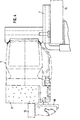
- the sanding belt runs vertically with its running direction, but with its running direction parallel to the work table. Again, two clamping positions are possible, in which the sanding belt is directed towards the work table and on the other hand away from the work table. In one case, plate-shaped workpieces of large dimensions can be safely placed on the work table and ground. In the other case, it is easy to grind any work piece outside the work table.
- the support table connected to the hand-held belt grinding machine can advantageously be used to support these workpieces.
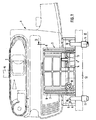
- a hand-held belt grinder 1 with an upward, horizontally running grinding belt 2 is removably attached to a base frame 3 by means of a fastening screw 4.
- the base frame 3 consists of a base plate 5, on the narrow side 6 of which an angle plate 7 is removably fastened by means of screws 8.
- Both base plate 5 and angle plate 7 have through bores 9 into which the holding brackets 10 of clamping claws 11 engage, with which the base frame 3 can be clamped onto a work table 12.
- the hand belt grinding machine is clamped in a known manner on the work table 12 by means of the base plate 5 in such a way that the grinding belt 2 runs horizontally and parallel to the work table and a workpiece 15 can be placed on the grinding belt 2 from above.
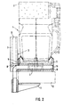
- the angle plate 7 is clamped on the work table 12 so that the sanding belt 2 is perpendicular and with the running direction parallel to the work table and is directed against the work table. It is thus possible to place plate-shaped workpieces 15 of any size on the work table using an intermediate layer 16 and to grind them perfectly on their narrow surface 17.
- the drive belt and the dust bag, not shown, are directed upwards and thus do not hinder the clamping of the hand-held belt grinder.
Landscapes
- Engineering & Computer Science (AREA)
- Mechanical Engineering (AREA)
- Finish Polishing, Edge Sharpening, And Grinding By Specific Grinding Devices (AREA)
Applications Claiming Priority (2)
| Application Number | Priority Date | Filing Date | Title |
|---|---|---|---|
| DE8329689U | 1983-10-14 | ||
| DE19838329689 DE8329689U1 (de) | 1983-10-14 | 1983-10-14 | Untergestell fuer handbandschleifmaschinen |
Publications (2)
| Publication Number | Publication Date |
|---|---|
| EP0138112A2 true EP0138112A2 (fr) | 1985-04-24 |
| EP0138112A3 EP0138112A3 (fr) | 1986-10-08 |
Family
ID=6757994
Family Applications (1)
| Application Number | Title | Priority Date | Filing Date |
|---|---|---|---|
| EP84111444A Withdrawn EP0138112A3 (fr) | 1983-10-14 | 1984-09-26 | Support pour ponceuse à bande portable |
Country Status (2)
| Country | Link |
|---|---|
| EP (1) | EP0138112A3 (fr) |
| DE (1) | DE8329689U1 (fr) |
Cited By (2)
| Publication number | Priority date | Publication date | Assignee | Title |
|---|---|---|---|---|
| FR2759009A1 (fr) * | 1997-02-04 | 1998-08-07 | Bosch Gmbh Robert | Ponceuse manuelle a bande |
| US7207875B2 (en) | 2003-10-14 | 2007-04-24 | Black & Decker Inc. | Sanding frame and stand for a belt sander |
Families Citing this family (1)
| Publication number | Priority date | Publication date | Assignee | Title |
|---|---|---|---|---|
| DE8329689U1 (de) * | 1983-10-14 | 1984-01-26 | Karl M. Reich Maschinenfabrik GmbH, 7440 Nürtingen | Untergestell fuer handbandschleifmaschinen |
Family Cites Families (6)
| Publication number | Priority date | Publication date | Assignee | Title |
|---|---|---|---|---|
| DE1025752B (de) * | 1953-11-10 | 1958-03-06 | Bosch Gmbh Robert | Leichtes, ortsbewegliches Bandschleifgeraet |
| US3212541A (en) * | 1963-02-19 | 1965-10-19 | Stanley Works | Cutting guide |
| US3664614A (en) * | 1969-11-26 | 1972-05-23 | Charles H Baechle | Power tool accessory |
| DE2421954C2 (de) * | 1974-05-07 | 1983-09-08 | Eugen Lutz GmbH u. Co Maschinenfabrik, 7130 Mühlacker | Winkelführung für stationär angeordnete oder mobile Hand-Oberfräsen |
| US4085552A (en) * | 1977-03-11 | 1978-04-25 | Irvin Industries, Inc. | Work tool stand |
| DE8329689U1 (de) * | 1983-10-14 | 1984-01-26 | Karl M. Reich Maschinenfabrik GmbH, 7440 Nürtingen | Untergestell fuer handbandschleifmaschinen |
-
1983
- 1983-10-14 DE DE19838329689 patent/DE8329689U1/de not_active Expired
-
1984
- 1984-09-26 EP EP84111444A patent/EP0138112A3/fr not_active Withdrawn
Cited By (2)
| Publication number | Priority date | Publication date | Assignee | Title |
|---|---|---|---|---|
| FR2759009A1 (fr) * | 1997-02-04 | 1998-08-07 | Bosch Gmbh Robert | Ponceuse manuelle a bande |
| US7207875B2 (en) | 2003-10-14 | 2007-04-24 | Black & Decker Inc. | Sanding frame and stand for a belt sander |
Also Published As
| Publication number | Publication date |
|---|---|
| EP0138112A3 (fr) | 1986-10-08 |
| DE8329689U1 (de) | 1984-01-26 |
Similar Documents
| Publication | Publication Date | Title |
|---|---|---|
| DE2303557B2 (de) | Vorrichtung zum Festlegen eines oder mehrerer Nahmaschinenmesser beim Schleifen an einer Stichelschleifmaschine | |
| EP0583753B1 (fr) | Dispositif de butée avec dispositif de fraisage des bords | |
| EP0138112A2 (fr) | Support pour ponceuse à bande portable | |
| EP0117305B1 (fr) | Etabli | |
| EP2340149B1 (fr) | Outil à ruban abrasif réglable | |
| DE2920197C2 (de) | Fräsvorrichtung zum Anfasen der Kanten von Werkstücken | |
| DE4210819C1 (en) | Equipment for e.g. smoothing or polishing angled surfaces - includes retaining rod which extends in or parallel to direction of movement in plane of symmetry | |
| DE4211738C2 (de) | Vorrichtung zum stationären Betrieb motorgetriebener spanabhebender Handarbeitsgeräte | |
| DE19523424A1 (de) | Anschlagvorrichtung für ein Kantenbearbeitungsgerät | |
| DE3316694C1 (de) | Kantenschleifmaschine | |
| DE19531270A1 (de) | Hand-Oszillationsmaschine | |
| AT413958B (de) | Stufenlos verstellbare bandschleifvorrichtung | |
| EP0027219B1 (fr) | Ponçeuse à bande portative avec cadre de guidage | |
| DE4006662C2 (fr) | ||
| DE339965C (de) | Ein Verfahren, um die Form der Schneidecken von profilierten Drehund Hobelstaehlen, insbesondere des Stahles nach Patent 310795, der Form der gewoehnlichen Dreh- und Hobelstaehle naeher zu bringen | |
| DE1907372A1 (de) | Fraesvorsatz | |
| DE3344381C2 (fr) | ||
| CH419886A (de) | Bandschleifmaschine für die Holzbearbeitung | |
| AT73511B (de) | Vorrichtung zum Einspannen und Schalten zu bekantender Steinplatten. | |
| DE492929C (de) | Polieren profilierter Glanzleisten | |
| DE4315985A1 (de) | Hobelmesser- und Stecheisen-Schleifvorrichtung mit Führungswagen | |
| DE2808715A1 (de) | Schleifmaschine zum anfasen von kacheln | |
| DE1652072B2 (fr) | ||
| DE2745668B1 (de) | Elektromaschine fuer Handbetrieb | |
| DE2025374A1 (de) | Vorrichtung zum stationären Betrieb von in eine motorisch angetriebene Hand bohrmaschine eingesetzten, umlaufenden Werkzeugen |
Legal Events
| Date | Code | Title | Description |
|---|---|---|---|
| PUAI | Public reference made under article 153(3) epc to a published international application that has entered the european phase |
Free format text: ORIGINAL CODE: 0009012 |
|
| AK | Designated contracting states |
Designated state(s): AT CH FR GB LI NL |
|
| RTI1 | Title (correction) | ||
| PUAL | Search report despatched |
Free format text: ORIGINAL CODE: 0009013 |
|
| AK | Designated contracting states |
Kind code of ref document: A3 Designated state(s): AT CH FR GB LI NL |
|
| STAA | Information on the status of an ep patent application or granted ep patent |
Free format text: STATUS: THE APPLICATION IS DEEMED TO BE WITHDRAWN |
|
| 18D | Application deemed to be withdrawn |
Effective date: 19870409 |
|
| RIN1 | Information on inventor provided before grant (corrected) |
Inventor name: BISCHOF, EDGAR Inventor name: KUHN, REINER |