EP0138172A2 - Machine d'emballage - Google Patents
Machine d'emballage Download PDFInfo
- Publication number
- EP0138172A2 EP0138172A2 EP84111983A EP84111983A EP0138172A2 EP 0138172 A2 EP0138172 A2 EP 0138172A2 EP 84111983 A EP84111983 A EP 84111983A EP 84111983 A EP84111983 A EP 84111983A EP 0138172 A2 EP0138172 A2 EP 0138172A2
- Authority
- EP
- European Patent Office
- Prior art keywords
- packaging machine
- material web
- machine according
- transport channel
- cover
- Prior art date
- Legal status (The legal status is an assumption and is not a legal conclusion. Google has not performed a legal analysis and makes no representation as to the accuracy of the status listed.)
- Withdrawn
Links
Images


Classifications
-
- B—PERFORMING OPERATIONS; TRANSPORTING
- B65—CONVEYING; PACKING; STORING; HANDLING THIN OR FILAMENTARY MATERIAL
- B65B—MACHINES, APPARATUS OR DEVICES FOR, OR METHODS OF, PACKAGING ARTICLES OR MATERIALS; UNPACKING
- B65B57/00—Automatic control, checking, warning, or safety devices
- B65B57/005—Safety-devices
-
- B—PERFORMING OPERATIONS; TRANSPORTING
- B65—CONVEYING; PACKING; STORING; HANDLING THIN OR FILAMENTARY MATERIAL
- B65G—TRANSPORT OR STORAGE DEVICES, e.g. CONVEYORS FOR LOADING OR TIPPING, SHOP CONVEYOR SYSTEMS OR PNEUMATIC TUBE CONVEYORS
- B65G43/00—Control devices, e.g. for safety, warning or fault-correcting
-
- F—MECHANICAL ENGINEERING; LIGHTING; HEATING; WEAPONS; BLASTING
- F16—ENGINEERING ELEMENTS AND UNITS; GENERAL MEASURES FOR PRODUCING AND MAINTAINING EFFECTIVE FUNCTIONING OF MACHINES OR INSTALLATIONS; THERMAL INSULATION IN GENERAL
- F16P—SAFETY DEVICES IN GENERAL; SAFETY DEVICES FOR PRESSES
- F16P3/00—Safety devices acting in conjunction with the control or operation of a machine; Control arrangements requiring the simultaneous use of two or more parts of the body
- F16P3/02—Screens or other safety members moving in synchronism with members which move to and fro
Definitions
- the invention relates to a packaging machine according to the preamble of claim 1.
- the material web with one or more packs is passed next to one another through the work stations.
- Workstations such as a deep-drawing device or a sealing device are briefly closed during the workflow and then opened to such an extent that the packs can be led out of the workstation on the outlet side.
- the material web with the packs is then passed through a transverse cutting device and longitudinal cutting device, these stations in the area of the knives having an opening area through which the material web with the packaging is passed.
- the material web that is passed through has no packs, or in which the machine runs without a material web being passed through, or in which the packs are oriented so asymmetrically that the entire opening area is not filled. In these cases it is possible to reach into the workstations through the opening area.
- From DE-PS 30 10 657 is a packaging machine known the preamble, which has a protective device with which reaching into a work station is to be avoided when the opening area is located above a material web.
- the protective device is not suitable for preventing reaching into an opening area which is located below a material web.
- the opening area is always below the material web when the packs are protruding on the underside of the material web.
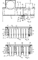
- the packaging machine 1 has a frame 30 with two side walls 31, 32, which has a deep-drawing station 7, an evacuation and sealing station 8, a cross-cutting device 9 and a longitudinal cutting device 10 in a known manner.
- a supply roll 5 with a material web 3 is attached on the input side in front of the deep-drawing station 7.
- Transport devices in the form of gripper chains 33, 34 are provided on the side walls 31, 32 in a known manner, which grip the material web from the supply roll 5 and guide it through the work stations to the opposite end of the packaging machine on the output side. Objects to be packaged are inserted into these.
- an upper film 4 is fed from a supply roll 6 via the containers.
- the packaging covered in this way is sealed or welded in the evacuation and sealing station 8.
- the work stations 7 and 8 each consist of an upper tool and lower parts which can be moved back and forth in the direction of the arrows 35, 36 for closing the station or opening for the further transport of the containers 11.
- the packaging machine shown in FIG. 1 has a protection on the output side of the cross-cutting device 9 direction 13 on.
- plate-shaped bottoms 16 are arranged at such a distance from the underside of the material web 3 downwards that, together with the side walls 31 and 32, they form a transport channel 2 through which the containers 11 just fit.
- the respective cross section on the output side of this transport channel forms an area 27.
- the protective device On the output side of the area 27, the protective device has an element in the form of a cover 14. This cover 14 is pivotally mounted about an axis 15 which is at a distance from the material web 3 downwards which is at least equal to the distance of the base 16 from the material web.
- the dimensions of the cover 14 are chosen so that, in the embodiments shown in FIGS. 2 to 4, they extend in their projection onto the region 27 to almost the underside of the material web 3 and extend in width so far that the region 27 is covered.
- the cover 14 is designed such that in its rest position it is in the position shown in the solid position, in which it extends essentially parallel to the region 27.
- a stop 20 is provided, against which the cover 14 strikes in the first position shown, so that the movement towards the rest position is limited.
- the cover 14 has such a mass distribution by attaching a counterweight 18 in the position shown in Fig. 2 below the axis 15 that the total center of gravity 37 of the cover 14 is so much lower than the axis 15 seen in the vertical direction that the Cover 14 without Action of additional forces in the manner of a standing man moved into the first position drawn with a solid line in FIG. 2.
- the cover 14 can be deflected by the action of a force in the direction of the feed direction of the material web from its first position shown into the second position shown in broken lines in FIG. 2 in such a way that it releases the region 27 of the transport channel 2.
- the cover 14 can also be provided which move the cover 14 back into the first position or pretension the cover into this position when an external force is removed.
- the design can take the form of a spring which acts on the cover 14 at a distance from the axis 15.
- an alignment device 26 in the form of an air nozzle can be provided for blowing on the cover 14 in such a way that it is pressed into the first position.
- a friction drive or a magnetic drive can also be used.
- the cover 14 can also be designed such that it is formed from a flexible material and is clamped below the base 16 in the position shown in FIG. 2.
- the cover can be deflected by the action of a force in the feed direction of the material web so that the region 27 is released. After the force ceases, the cover snaps back into the starting position shown. It is prevented from moving beyond the first position shown towards the work station 9 by a stop.
- the cover 14 is transverse direction to region 27 preferably divided into a plurality of sub-elements.
- the sub-elements are each independently of the adjacent sub-elements as described above in the first position and deflected from this by the action of an external force by providing a counterweight or a spring or the like for resetting for each sub-element 17.
- the distance between adjacent sub-elements 17 is selected so that the movement does not interfere with one another, but on the other hand it is not possible to reach through between two sub-elements.
- the subdivision and thus the number of sub-elements 17 depends on the shape of the packs to be guided next to one another in the transport channel 2. It is chosen so that in cases in which the area 27 is not completely filled by packs, partial elements 17 in the first position cover the areas even when a pack is passed through which are not filled by a pack.
- support plates 23 can be provided between the individual containers according to the exemplary embodiment according to FIG. 4. These support plates 23 can either be arranged between individual sub-elements 17 or be designed such that they each cover a sub-element 17 moved into the deflected position in the ways shown in FIGS. 4 and 5.
- the partial elements 17 are designed in the form of a plate, in particular in the embodiment shown in FIG. 5. Instead, they can also be tubular or rod-shaped.
- a protective hood 21 is arranged above the material web, by means of which reaching in from above is to be prevented.
- the cover 14 can be made so long that it comes from the deflected position on the protective hood 21 to limit further movement beyond the first position.
- the stop 22 is provided at the lower end of the cover.
- the partial elements 17 of the cover 14 are initially in the position shown in FIG. 2. As soon as a container 11 abuts at least one of the sub-elements 17, it is deflected into the dashed position so that the path for the container to be carried out is opened. Only the partial elements 17 remain in the first position, which are not acted upon by a container. The deflected partial elements 17 graze along the underside of the container 11, so that any space between the bottom 16 of the transport channel 2 and the bottom of the container 11 remains covered. As soon as the container 11 has moved forward so far that it no longer acts on the partial elements 17 deflected by it, these move back into the first position and close off the region 27 again. This ensures that it is not possible to reach into the station through the area 27 even at the points.
- the protective device 13 is located on the output side in front of the cross-cutting device 9.
- such protective devices can of course also be attached on the output side in front of all other workstations.
- the packaging machine 1 is operated for testing purposes without a film or with undeformed films, then depending on the length of the cover 14, the upper end thereof lies against the undeformed film or the protective hood 21, as a result of which the cover 14 is in an oblique intermediate position between the first and the second position, or the cover 14 is pressed by the counterweight 18 to the stop 20 in the first position. In both cases, the transport channel is blocked against intervention from the exit end.
Landscapes
- Engineering & Computer Science (AREA)
- General Engineering & Computer Science (AREA)
- Mechanical Engineering (AREA)
- Containers And Plastic Fillers For Packaging (AREA)
- Wrapping Of Specific Fragile Articles (AREA)
- Auxiliary Devices For And Details Of Packaging Control (AREA)
Applications Claiming Priority (2)
| Application Number | Priority Date | Filing Date | Title |
|---|---|---|---|
| DE3337459 | 1983-10-14 | ||
| DE19833337459 DE3337459A1 (de) | 1983-10-14 | 1983-10-14 | Verpackungsmaschine |
Publications (2)
| Publication Number | Publication Date |
|---|---|
| EP0138172A2 true EP0138172A2 (fr) | 1985-04-24 |
| EP0138172A3 EP0138172A3 (fr) | 1985-06-05 |
Family
ID=6211875
Family Applications (1)
| Application Number | Title | Priority Date | Filing Date |
|---|---|---|---|
| EP84111983A Withdrawn EP0138172A3 (fr) | 1983-10-14 | 1984-10-05 | Machine d'emballage |
Country Status (3)
| Country | Link |
|---|---|
| EP (1) | EP0138172A3 (fr) |
| JP (1) | JPS6099803A (fr) |
| DE (1) | DE3337459A1 (fr) |
Cited By (2)
| Publication number | Priority date | Publication date | Assignee | Title |
|---|---|---|---|---|
| US5048268A (en) * | 1989-08-29 | 1991-09-17 | W. R. Grace & Co.-Conn. | Vacuum packaging method and apparatus |
| FR2723574A1 (fr) * | 1994-08-09 | 1996-02-16 | Productique Comp Gen De | Installation de stockage automatique de bacs |
Families Citing this family (2)
| Publication number | Priority date | Publication date | Assignee | Title |
|---|---|---|---|---|
| DE102019214962A1 (de) * | 2019-09-30 | 2021-04-01 | Multivac Sepp Haggenmüller Se & Co. Kg | Tiefziehverpackungsmaschine mit Schutzabdeckung |
| DE102019214963A1 (de) * | 2019-09-30 | 2021-04-01 | Multivac Sepp Haggenmüller Se & Co. Kg | Tiefziehverpackungsmaschine mit Schutzvorrichtung |
Family Cites Families (4)
| Publication number | Priority date | Publication date | Assignee | Title |
|---|---|---|---|---|
| DD83733A (fr) * | ||||
| US3698527A (en) * | 1971-01-15 | 1972-10-17 | Nicholas W Wiggers | Press guard and parts monitor |
| US3896683A (en) * | 1973-11-05 | 1975-07-29 | Union Special Corp | Pivotal guard for punch presses |
| DE3010657C2 (de) * | 1980-03-20 | 1983-06-23 | Psverpackung Gmbh, 2110 Buchholz | Schutzvorrichtung für Tiefzieh- oder -drückmaschine einer Verpackungseinrichtung |
-
1983
- 1983-10-14 DE DE19833337459 patent/DE3337459A1/de not_active Ceased
-
1984
- 1984-10-05 EP EP84111983A patent/EP0138172A3/fr not_active Withdrawn
- 1984-10-12 JP JP21507884A patent/JPS6099803A/ja active Pending
Cited By (2)
| Publication number | Priority date | Publication date | Assignee | Title |
|---|---|---|---|---|
| US5048268A (en) * | 1989-08-29 | 1991-09-17 | W. R. Grace & Co.-Conn. | Vacuum packaging method and apparatus |
| FR2723574A1 (fr) * | 1994-08-09 | 1996-02-16 | Productique Comp Gen De | Installation de stockage automatique de bacs |
Also Published As
| Publication number | Publication date |
|---|---|
| DE3337459A1 (de) | 1985-05-02 |
| JPS6099803A (ja) | 1985-06-03 |
| EP0138172A3 (fr) | 1985-06-05 |
Similar Documents
| Publication | Publication Date | Title |
|---|---|---|
| DE3316065C2 (de) | Verfahren zum Füllen, Entlüften und Verschließen von Säcken | |
| DE60012819T2 (de) | Anbringen von Verschliessbändern an einer Verpackung | |
| EP0544704B1 (fr) | Dispositif d'enveloppement d'une unite d'emballage | |
| DE69718555T2 (de) | Vorrichtung zum Stapeln von Blättern, insbesondere Geldscheinen, und zum Übertragen der Stapel | |
| DE69109202T2 (de) | Filmzufuhrmagazin. | |
| DE3424782A1 (de) | Maschine zum herstellen von kartons, schachteln und dergleichen | |
| EP0734981B1 (fr) | Dispositif de chargement | |
| DE2127310C3 (de) | Fördereinrichtung für Flaschen oder ähnliches Fördergut | |
| EP0138172A2 (fr) | Machine d'emballage | |
| EP0483446B1 (fr) | Dispositif de protection pour machine d'emballage | |
| EP0076908B1 (fr) | Dispositif pour le cerclage d'objets | |
| EP0059840A2 (fr) | Dispositif pour empiler et emballer des articles plats | |
| EP0062785A1 (fr) | Dispositif pour dévier du courant de transport des articles plats et flexibles, en particulier des articles imprimés | |
| DE29901565U1 (de) | Vorrichtung zum Herstellen und Umhüllen von Schmelzenportionen | |
| DE29904426U1 (de) | Vorrichtung zum Stapeln und Entstapeln | |
| DE19882452C2 (de) | Fördervorrichtung für Behälter in einer Abfüll- und Falzanlage | |
| DE2242826A1 (de) | Vorrichtung zum transportieren einer kunststoffolienbahn | |
| DE652087C (de) | Einfalltrichter fuer Matrizensetz- und Zeilengiessmaschinen, in dem die Matrizen durch seitlich vorspringende Flansche, die sich gegen die Ohren der Matrizen legen, und durch Blattfedern, die leicht gegen den mittleren Teil der Matrizen druecken, in aufrechter Lage gehalten werden | |
| DE3432331A1 (de) | Verpackungsmaschine fuer in huellpackungen einzubringende, doppelfolig verklebte medikamentenpflaster | |
| DE3716660A1 (de) | Aufteilanlage fuer plattenfoermige werkstuecke | |
| DE69800815T2 (de) | Bogenverteilungsvorrichtung | |
| DE1623144C3 (de) | Vorrichtung zum Sortieren und Stapeln von Schnittholz | |
| DE2924186C2 (de) | Als Dosier-Schieber ausgebildeter Verschluß für einen Silo-Auslauf | |
| DE69700877T2 (de) | Schneideanordnung | |
| DE9204236U1 (de) | Sitzbezug zum Schutz eines Kraftfahrzeug-Sitzes aus einem doppellagigen Teil aus Kunststoffolie |
Legal Events
| Date | Code | Title | Description |
|---|---|---|---|
| PUAI | Public reference made under article 153(3) epc to a published international application that has entered the european phase |
Free format text: ORIGINAL CODE: 0009012 |
|
| PUAL | Search report despatched |
Free format text: ORIGINAL CODE: 0009013 |
|
| AK | Designated contracting states |
Designated state(s): CH FR GB LI SE |
|
| AK | Designated contracting states |
Designated state(s): CH FR GB LI SE |
|
| RTI1 | Title (correction) | ||
| 17P | Request for examination filed |
Effective date: 19850508 |
|
| STAA | Information on the status of an ep patent application or granted ep patent |
Free format text: STATUS: THE APPLICATION HAS BEEN WITHDRAWN |
|
| 18W | Application withdrawn |
Withdrawal date: 19870402 |
|
| RIN1 | Information on inventor provided before grant (corrected) |
Inventor name: NATTERER, JOHANN Inventor name: FRANZ, DOLF |